EP0908321A2 - Cartouche pour ruban encreur et méthode adaptée pour tendre un ruban de colorant associé - Google Patents
Cartouche pour ruban encreur et méthode adaptée pour tendre un ruban de colorant associé Download PDFInfo
- Publication number
- EP0908321A2 EP0908321A2 EP98203255A EP98203255A EP0908321A2 EP 0908321 A2 EP0908321 A2 EP 0908321A2 EP 98203255 A EP98203255 A EP 98203255A EP 98203255 A EP98203255 A EP 98203255A EP 0908321 A2 EP0908321 A2 EP 0908321A2
- Authority
- EP
- European Patent Office
- Prior art keywords
- dye
- dye ribbon
- spool
- ribbon
- flexible portion
- Prior art date
- Legal status (The legal status is an assumption and is not a legal conclusion. Google has not performed a legal analysis and makes no representation as to the accuracy of the status listed.)
- Withdrawn
Links
- 238000000034 method Methods 0.000 title claims abstract description 13
- 230000003213 activating effect Effects 0.000 claims description 4
- 239000000463 material Substances 0.000 description 5
- 230000008878 coupling Effects 0.000 description 3
- 238000010168 coupling process Methods 0.000 description 3
- 238000005859 coupling reaction Methods 0.000 description 3
- NJPPVKZQTLUDBO-UHFFFAOYSA-N novaluron Chemical compound C1=C(Cl)C(OC(F)(F)C(OC(F)(F)F)F)=CC=C1NC(=O)NC(=O)C1=C(F)C=CC=C1F NJPPVKZQTLUDBO-UHFFFAOYSA-N 0.000 description 3
- 230000007423 decrease Effects 0.000 description 2
- 239000004033 plastic Substances 0.000 description 2
- 229920003023 plastic Polymers 0.000 description 2
- 239000004695 Polyether sulfone Substances 0.000 description 1
- 239000004697 Polyetherimide Substances 0.000 description 1
- 239000004642 Polyimide Substances 0.000 description 1
- 239000004743 Polypropylene Substances 0.000 description 1
- 229920002301 cellulose acetate Polymers 0.000 description 1
- 238000001514 detection method Methods 0.000 description 1
- 230000007257 malfunction Effects 0.000 description 1
- 238000012986 modification Methods 0.000 description 1
- 230000004048 modification Effects 0.000 description 1
- 229920001643 poly(ether ketone) Polymers 0.000 description 1
- 229920001281 polyalkylene Polymers 0.000 description 1
- 239000004417 polycarbonate Substances 0.000 description 1
- 229920000515 polycarbonate Polymers 0.000 description 1
- 229920006393 polyether sulfone Polymers 0.000 description 1
- 229920001601 polyetherimide Polymers 0.000 description 1
- 229920001721 polyimide Polymers 0.000 description 1
- -1 polypropylene Polymers 0.000 description 1
- 229920001155 polypropylene Polymers 0.000 description 1
- 230000002265 prevention Effects 0.000 description 1
- 239000012858 resilient material Substances 0.000 description 1
- KKEYFWRCBNTPAC-UHFFFAOYSA-L terephthalate(2-) Chemical compound [O-]C(=O)C1=CC=C(C([O-])=O)C=C1 KKEYFWRCBNTPAC-UHFFFAOYSA-L 0.000 description 1
- 230000037303 wrinkles Effects 0.000 description 1
Images


Classifications
-
- B—PERFORMING OPERATIONS; TRANSPORTING
- B41—PRINTING; LINING MACHINES; TYPEWRITERS; STAMPS
- B41J—TYPEWRITERS; SELECTIVE PRINTING MECHANISMS, i.e. MECHANISMS PRINTING OTHERWISE THAN FROM A FORME; CORRECTION OF TYPOGRAPHICAL ERRORS
- B41J17/00—Mechanisms for manipulating page-width impression-transfer material, e.g. carbon paper
- B41J17/32—Detachable carriers or holders for impression-transfer material mechanism
-
- B—PERFORMING OPERATIONS; TRANSPORTING
- B41—PRINTING; LINING MACHINES; TYPEWRITERS; STAMPS
- B41J—TYPEWRITERS; SELECTIVE PRINTING MECHANISMS, i.e. MECHANISMS PRINTING OTHERWISE THAN FROM A FORME; CORRECTION OF TYPOGRAPHICAL ERRORS
- B41J35/00—Other apparatus or arrangements associated with, or incorporated in, ink-ribbon mechanisms
- B41J35/04—Ink-ribbon guides
- B41J35/08—Ink-ribbon guides with tensioning arrangements
Definitions
- This invention generally relates to dye cartridge apparatus and methods and more particularly relates to a dye cartridge system and method adapted to tension a dye ribbon associated therewith.
- a typical thermal resistive printer has an enclosure for enclosing the components of the printer.
- Receiver medium is fed from a supply tray to a print head housed in the enclosure.
- the receiver medium fed to the print head is brought into contact with a dye donor web carried by a dye donor cassette disposed near the print head.
- the resistive elements in print head heat activates the dye donor web to transfer the dye to the receiver medium in order to print an output image on the receiver medium.
- the dye donor cassette includes two parallel spaced-apart side arms having ends thereof respectively connected to a pair of end shells.
- the spaced-apart side arms define an opening therebetween.
- a supply spool is disposed in a first one of the shells and a take-up spool is disposed in a second one of the shells.
- One end of the dye donor web is mounted on the supply spool within the first shell and the other end of the dye donor web is mounted on the take-up spool in the second shell.
- the dye donor web is suspended between the supply spool and the take-up spool and covers the opening defined between the arms.
- motors that may be connected to the supply spool and the take-up spool operate the supply spool and the take-up spool so that the dye donor web is supplied from the supply spool and taken-up on the take-up spool.
- the print head which is aligned with the opening between the arm and which is disposed on one side of the dye donor web activates the dye donor web to transfer dye therefrom to the receiver medium also aligned with the opening but disposed on another side of the dye donor web in order to print an image on the receiver medium.
- the dye donor web in order to obtain suitable printed images, it is desirable to tension the dye donor web as the dye donor web is supplied from the supply spool and taken-up by the take-up spool.
- the purpose of tensioning the dye donor web is to avoid an excessive amount of the donor web from unspooling from the supply spool or the take-up spool.
- Unspooling of the dye donor web from either the supply spool or the take-up spool could cause any one of several problems to arise during printing. For example, such unspooling could cause non-uniformity of dye transfer to the receiver medium. As another example, such unspooling could cause excessive amounts of donor web to enter into the print head and receiver interface region thereby resulting in image artifacts appearing on the receiver medium. As yet another example, such unspooling could cause excessive slack in the donor web, which in turn could lead to mechanical malfunctions in the printer's components.
- a drag brake mounted for this purpose is disclosed by US-A-5,661,515 titled "Printer With Feed Fault Detection”. More specifically, this patent discloses a drag brake mounted in a printer and which connects with a supply spool through a disengagement coupling to maintain tension on the donor web during printing.
- the drag brake disclosed by the Hevenor patent requires use of a slip-clutch coupling permanently mounted in the printer. This is an additional component that increases complexity and cost of the printer.
- an object of the present invention is to provide a dye cartridge system and method adapted to tension a dye ribbon associated therewith, which cartridge system and method obviates the need to add complex components to the printer in order to tension the dye ribbon.
- the invention resides in a cartridge system adapted to tension a dye ribbon associated therewith, characterized by: a spool having the dye ribbon wound thereabout; and a cartridge body housing said spool, said cartridge body having a flexible portion movable from a first position thereof spaced-apart from the dye ribbon to a second position thereof into engagement with the dye ribbon for imposing a drag force on the dye ribbon, so that the dye ribbon is tensioned as the drag force is imposed on the dye ribbon.
- cartridge system comprises a first spool disposed in an enclosure belonging to a printer.
- the first spool has the dye ribbon wound thereabout.
- the dye ribbon has a leading end portion extending from the first spool.
- a second spool is associated with the first spool, the second spool having the leading end portion of the dye ribbon connected thereto.
- the dye ribbon has an extended portion thereof suspended between the first spool and the second spool.
- a cartridge body which houses the first spool and the second spool, has a flexible portion movable from a first position thereof spaced-apart from the dye ribbon wound about the first spool to a second position thereof into engagement with the dye ribbon wound about the first spool.
- a print head is disposed adjacent the extended portion of the dye ribbon to activate the dye ribbon for transferring dye from the dye ribbon to a receiver medium.
- a biasing member engages the flexible portion of the cartridge for biasing the flexible portion, so that the flexible portion moves from the first position thereof to the second position thereof as the flexible portion is biased.
- the biasing member may be a spring member, a pneumatic cylinder, or any suitable means of biasing the flexible portion into engagement with the dye ribbon wound about the first spool.
- the print head may be a thermal resistive print head for thermally activating the dye ribbon.
- the biasing member can be used to produce drag force on either or both of first spool and second spool. The drag force applied when using biasing members on both spools can accept equal or unequal tension force.
- a feature of the present invention is the provision of a dye cartridge having a flexible portion thereof engageable with the dye ribbon as the dye ribbon is wound about the first spool for imposing a drag force on the dye ribbon.
- An advantage of the present invention is that it reduces complexity of the printer.
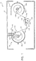
- FIG. 1 there is shown the subject matter of the present invention, which is a dye cartridge system, generally referred to as 10, useable with a printer apparatus, generally referred to as 15.
- Cartridge system 10 is adapted to tension a dye ribbon 20 associated therewith, as disclosed in more detail hereinbelow.
- Printer 15 may be a thermal resistive printer and dye ribbon 20 may comprise a plurality of color patches (not shown) for obtaining color images to be deposited on a receiver medium 30.
- Receiver medium 30 may be cut sheets of paper or transparency.
- printer 15 comprises an enclosure 40 enclosing a dye encasement or cartridge body therein, generally referred to as 50.
- cartridge body 50 is preferably formed from a resilient material, which may be a plastic material, such as polypropylene, polyalkylene, terephthalate, polyimide, polyether imide, polyether ketone, polyether sulfone, polycarbonate, cellulose acetate, or the like.
- Cartridge body 50 has a pair of parallel elongate spaced-apart side arms 60a and 60b defining a space or opening 70 therebetween for reasons provided hereinbelow.
- first spool such as a dye ribbon supply spool 100
- second spool such as a take-up spool 120
- Leading end portion 110 is connected to take-up spool 120.
- dye ribbon 20 defines an extended portion 125 thereof suspended between supply spool 100 and take-up spool 120.
- Supply spool 100 and take-up spool 120 may have suitable motors (not shown) engageable therewith for asynchronously rotating supply spool 100 and take-up spool 120 in the directions shown by arrows 130a and 130b, respectively.
- a print head 140 located adjacent the extended portion 125.
- Print head 140 may be a thermal resistive print head having a plurality of thermal resistive elements (not shown) therein for thermally activating dye ribbon 20 in order to transfer dye from dye ribbon 20 to receiver medium 30, which receiver medium 30 is interposed between a support member, such as a platen roller 150, and print head 140.
- platen roller 150 The purpose of platen roller 150 is to provide support to receiver medium 30 as print head presses against receiver medium 30 to deposit an image thereon.
- Platen roller 150 may be rotatable by means of a rotatable spindle 160 on which platen roller 150 may be mounted. Platen roller 150 may be rotatable for in order to obtain constant velocity of receiver medium 30.
- a pair of rollers 170a and 170b may be provided on either side of print head 140 and engaging extended portion 125 of dye ribbon 20 for the prevention of wrinkles in the dye ribbon 20.
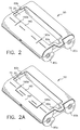
- first shell 80a belonging to cartridge body 50 preferably includes a flexible portion or flexible flap 180 integrally attached thereto.
- flap 180 is defined by a pair of parallel spaced-apart slits 190a and 190b cut into first shell 80a on either side of flap 180.
- Cartridge body 50 is formed of the previously mentioned plastic material. This material allows flap 180 to be resilient or flexible, which is important for reasons provided presently.
- a pair of L-shaped slits 195a/b formed on opposite sides of flap 180, such as to define an intermediate portion 197 therebetween.
- the advantage of this configuration is that it allows greater flexibility in flap 180. This will allow for a wider range of materials to achieve the desired flexibility. It is appreciated that the width of slits 195a/b and/or the width of portion 197 can be optimized to achieve the desired flexibility.
- a relief 199 extends between slits 190a and 190b.
- the advantage of this configuration is that it enhances the compliance of flap 180 as compared to relief 199 not being present.
- the intent of relief 199 is to reduce the cross section of flap 180 in order to achieve flexibility of flap 180. Therefore, of course, cross section of flap 180 can be reduced by other means.
- the cross section of flap 180 can be reduced by forming the relief on the side opposite of that shown. Also, there may be two reliefs, one on each side of flap 180.
- a biasing member 200 is disposed in printer 15 and is capable of engaging flap 180 for moving flap 180 from a first position thereof, generally referred to as 210, spaced-apart from dye ribbon 20 wound about supply spool 100 to a second position thereof, generally referred to as 220, into engagement with dye ribbon 20 wound about supply spool 100.
- biasing member 200 may exert a biasing force of about 8 to 15 inch-ounce.
- flap 180 is biased it will contact or engage dye ribbon 20 wound about supply spool 100 and will impose a drag force on dye ribbon 20 in order to tension dye ribbon 20 as dye ribbon 20 is supplied from supply spool 100 to take-up spool 120.
- Biasing member 200 is selected such that it creates a substantially constant biasing force on dye ribbon 20 as the diameter of dye ribbon 20 on supply spool 100 decrease as dye ribbon 20 is supplied from supply spool 100.
- the tensioning force acting on dye ribbon 20 decreases as dye ribbon 20 is supplied from about supply spool 100.
- biasing member 200 is interposed between enclosure 40 and flap 180 and may be a coiled spring member.
- the biasing member can be used to produce drag force on either or both of supply spool 100 and take-up spool 120. The drag force applied when using biasing members on both spools 100/120 can accept equal or unequal tension force.
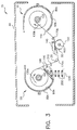
- FIG. 3 there is shown a second embodiment cartridge system 10 useable with printer 15, wherein flap 180 is formed in an underside portion of first shell 80a and biasing member 200 is interposed between flap 180 and a pedestal 230 disposed in enclosure 40.
- FIG. 4 there is shown a third embodiment cartridge system 10 useable with printer 15, wherein wherein flap 180 is formed in second shell 80b and biasing member 200 is interposed between flap 180 and enclosure 40 for tensioning dye ribbon 20 as dye ribbon 20 winds about take-up spool 120.
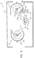
- FIG. 5 there is shown a fourth embodiment cartridge system useable with printer 15, wherein flap 180 is formed in an underside portion of second shell 80b and biasing member 200 is interposed between flap 180 and pedestal 230 disposed in enclosure 40.
- biasing member 200 which may a resilient spring, is disposed in first chamber 90a and interconnects flap 180 to an inner wall of first shell for biasing flap 180 into contact with dye ribbon 20 wound about first spool 100.
- biasing member 200 is a pneumatic cylinder interposed between enclosure 40 and flap 180.
- an advantage of the present invention is that it reduces complexity and cost of the printer. This is so because the dye cartridge body belonging to the cartridge system comprises an integrally attached flap for creating drag force on the dye ribbon, therefore making it unnecessary to include the additional component of a slip-clutch coupling permanently mounted in the printer.
- biasing member 200 may be attached to a door (not shown) belonging to a front side of printer 15, which door allows loading of cartridge body 50 into printer 15.
- biasing member 200 will engage flap 180 only when the door is closed and will disengage flap 180 when the door is opened for convenience of loading cartridge body 50 into printer 15.
Landscapes
- Impression-Transfer Materials And Handling Thereof (AREA)
Applications Claiming Priority (2)
| Application Number | Priority Date | Filing Date | Title |
|---|---|---|---|
| US947684 | 1992-09-21 | ||
| US08/947,684 US5835118A (en) | 1997-10-09 | 1997-10-09 | Dye cartridge system and method adapted to tension a dye ribbon associated therewith |
Publications (2)
| Publication Number | Publication Date |
|---|---|
| EP0908321A2 true EP0908321A2 (fr) | 1999-04-14 |
| EP0908321A3 EP0908321A3 (fr) | 1999-07-28 |
Family
ID=25486573
Family Applications (1)
| Application Number | Title | Priority Date | Filing Date |
|---|---|---|---|
| EP98203255A Withdrawn EP0908321A3 (fr) | 1997-10-09 | 1998-09-28 | Cartouche pour ruban encreur et méthode adaptée pour tendre un ruban de colorant associé |
Country Status (3)
| Country | Link |
|---|---|
| US (1) | US5835118A (fr) |
| EP (1) | EP0908321A3 (fr) |
| JP (1) | JPH11188940A (fr) |
Families Citing this family (4)
| Publication number | Priority date | Publication date | Assignee | Title |
|---|---|---|---|---|
| WO2009152360A1 (fr) * | 2008-06-13 | 2009-12-17 | Brady Worldwide, Inc. | Cartouche avec contre-tension de ruban |
| JP5804800B2 (ja) * | 2011-06-30 | 2015-11-04 | セイコーエプソン株式会社 | 処理装置 |
| JP6808433B2 (ja) * | 2016-10-05 | 2021-01-06 | キヤノン株式会社 | インクリボンカセットおよび印刷装置 |
| JP7352135B2 (ja) * | 2018-12-28 | 2023-09-28 | ブラザー工業株式会社 | フィルムカートリッジ、フィルムユニットおよび層転写装置 |
Citations (1)
| Publication number | Priority date | Publication date | Assignee | Title |
|---|---|---|---|---|
| US5661515A (en) | 1993-01-22 | 1997-08-26 | Gerber Scientific Products, Inc. | Printer with feed fault detection |
Family Cites Families (4)
| Publication number | Priority date | Publication date | Assignee | Title |
|---|---|---|---|---|
| JPS60240481A (ja) * | 1984-05-15 | 1985-11-29 | Toshiba Corp | 転写材収納カセツト |
| JPH066389B2 (ja) * | 1985-01-18 | 1994-01-26 | 株式会社リコー | 記録媒体用カセツト |
| JPH0274378A (ja) * | 1988-09-09 | 1990-03-14 | Sony Corp | リボンカートリッジ |
| JP2551062Y2 (ja) * | 1990-10-11 | 1997-10-22 | 大日本印刷株式会社 | 転写フィルム用カセット |
-
1997
- 1997-10-09 US US08/947,684 patent/US5835118A/en not_active Expired - Fee Related
-
1998
- 1998-09-28 EP EP98203255A patent/EP0908321A3/fr not_active Withdrawn
- 1998-10-09 JP JP10287658A patent/JPH11188940A/ja active Pending
Patent Citations (1)
| Publication number | Priority date | Publication date | Assignee | Title |
|---|---|---|---|---|
| US5661515A (en) | 1993-01-22 | 1997-08-26 | Gerber Scientific Products, Inc. | Printer with feed fault detection |
Also Published As
| Publication number | Publication date |
|---|---|
| US5835118A (en) | 1998-11-10 |
| EP0908321A3 (fr) | 1999-07-28 |
| JPH11188940A (ja) | 1999-07-13 |
Similar Documents
| Publication | Publication Date | Title |
|---|---|---|
| US5269612A (en) | Ribbon cartridge | |
| US5622440A (en) | Ink film cassette having a torque applying device therein | |
| JP2585711B2 (ja) | 感熱転写記録装置 | |
| US5835118A (en) | Dye cartridge system and method adapted to tension a dye ribbon associated therewith | |
| US6082913A (en) | Cartridge for printing | |
| US5499880A (en) | Print head includes donor guide and receiver guide | |
| JP3549370B2 (ja) | カートリッジおよびこのカートリッジを用いた記録装置 | |
| US9764572B2 (en) | Printer | |
| KR100210461B1 (ko) | 프린터 | |
| CA2122978A1 (fr) | Appareil et methode d'impression video | |
| JP2988602B2 (ja) | 記録装置 | |
| US6226023B1 (en) | Thermal printing media pack | |
| JPH0732693A (ja) | 記録装置 | |
| US5885014A (en) | Printer defining a reduced exterior envelope thereof and method of providing same | |
| EP1752299B1 (fr) | Appareil d'enregistrement | |
| EP0904947A1 (fr) | Cartouche à ruban encreur adapté pour reduir les dimensions externes d'une imprimante et procédé de sa préparation | |
| KR0124825Y1 (ko) | 칼라 프린터 | |
| US5927873A (en) | Printer defining a reduced exterior envelope thereof and method of providing same | |
| JP2994180B2 (ja) | ラベル作成用インクリボンカセット | |
| US5908250A (en) | Dye cartridge system adapted to reduce an exterior envelope of a printer and method of providing same | |
| JPH05301406A (ja) | 記録装置 | |
| JP3779607B2 (ja) | 熱転写プリンタ | |
| JPS63145066A (ja) | 記録装置 | |
| JPS6176382A (ja) | 記録装置 | |
| JP2005074728A (ja) | 熱転写式記録装置 |
Legal Events
| Date | Code | Title | Description |
|---|---|---|---|
| PUAI | Public reference made under article 153(3) epc to a published international application that has entered the european phase |
Free format text: ORIGINAL CODE: 0009012 |
|
| AK | Designated contracting states |
Kind code of ref document: A2 Designated state(s): AT BE CH CY DE DK ES FI FR GB GR IE IT LI LU MC NL PT SE |
|
| AX | Request for extension of the european patent |
Free format text: AL;LT;LV;MK;RO;SI |
|
| PUAL | Search report despatched |
Free format text: ORIGINAL CODE: 0009013 |
|
| AK | Designated contracting states |
Kind code of ref document: A3 Designated state(s): AT BE CH CY DE DK ES FI FR GB GR IE IT LI LU MC NL PT SE |
|
| AX | Request for extension of the european patent |
Free format text: AL;LT;LV;MK;RO;SI |
|
| RIC1 | Information provided on ipc code assigned before grant |
Free format text: 6B 41J 35/08 A, 6B 41J 17/32 B |
|
| AKX | Designation fees paid | ||
| REG | Reference to a national code |
Ref country code: DE Ref legal event code: 8566 |
|
| STAA | Information on the status of an ep patent application or granted ep patent |
Free format text: STATUS: THE APPLICATION IS DEEMED TO BE WITHDRAWN |
|
| 18D | Application deemed to be withdrawn |
Effective date: 20000129 |