EP0907594B1 - Rotationsbandabstreicher - Google Patents
Rotationsbandabstreicher Download PDFInfo
- Publication number
- EP0907594B1 EP0907594B1 EP97926987A EP97926987A EP0907594B1 EP 0907594 B1 EP0907594 B1 EP 0907594B1 EP 97926987 A EP97926987 A EP 97926987A EP 97926987 A EP97926987 A EP 97926987A EP 0907594 B1 EP0907594 B1 EP 0907594B1
- Authority
- EP
- European Patent Office
- Prior art keywords
- scraper
- belt
- rotary
- conveyor belt
- elements
- Prior art date
- Legal status (The legal status is an assumption and is not a legal conclusion. Google has not performed a legal analysis and makes no representation as to the accuracy of the status listed.)
- Expired - Lifetime
Links
- 230000000694 effects Effects 0.000 claims description 12
- 239000000463 material Substances 0.000 claims description 8
- 239000002184 metal Substances 0.000 claims description 8
- 229910052751 metal Inorganic materials 0.000 claims description 8
- 239000004033 plastic Substances 0.000 claims description 6
- 229920003023 plastic Polymers 0.000 claims description 6
- 229920001971 elastomer Polymers 0.000 claims description 5
- 239000005060 rubber Substances 0.000 claims description 5
- 229910001315 Tool steel Inorganic materials 0.000 claims description 3
- 229910045601 alloy Inorganic materials 0.000 claims description 3
- 239000000956 alloy Substances 0.000 claims description 3
- 239000007769 metal material Substances 0.000 claims description 3
- 239000004814 polyurethane Substances 0.000 claims description 3
- 229920002635 polyurethane Polymers 0.000 claims description 3
- 238000009434 installation Methods 0.000 claims description 2
- 125000006850 spacer group Chemical group 0.000 claims description 2
- 239000000470 constituent Substances 0.000 claims 1
- 230000005484 gravity Effects 0.000 claims 1
- 230000035508 accumulation Effects 0.000 abstract 1
- 238000009825 accumulation Methods 0.000 abstract 1
- 238000004140 cleaning Methods 0.000 description 22
- 230000033001 locomotion Effects 0.000 description 10
- 238000011161 development Methods 0.000 description 7
- 230000018109 developmental process Effects 0.000 description 7
- 230000002349 favourable effect Effects 0.000 description 4
- 238000003860 storage Methods 0.000 description 4
- 238000011109 contamination Methods 0.000 description 3
- 238000004519 manufacturing process Methods 0.000 description 2
- 238000007790 scraping Methods 0.000 description 2
- 230000001070 adhesive effect Effects 0.000 description 1
- 239000013590 bulk material Substances 0.000 description 1
- 238000010276 construction Methods 0.000 description 1
- 229910052500 inorganic mineral Inorganic materials 0.000 description 1
- 230000003993 interaction Effects 0.000 description 1
- 238000000034 method Methods 0.000 description 1
- 239000011707 mineral Substances 0.000 description 1
- 239000002245 particle Substances 0.000 description 1
- 230000002093 peripheral effect Effects 0.000 description 1
- 238000003825 pressing Methods 0.000 description 1
- 230000002787 reinforcement Effects 0.000 description 1
Images


Classifications
-
- B—PERFORMING OPERATIONS; TRANSPORTING
- B65—CONVEYING; PACKING; STORING; HANDLING THIN OR FILAMENTARY MATERIAL
- B65G—TRANSPORT OR STORAGE DEVICES, e.g. CONVEYORS FOR LOADING OR TIPPING, SHOP CONVEYOR SYSTEMS OR PNEUMATIC TUBE CONVEYORS
- B65G45/00—Lubricating, cleaning, or clearing devices
- B65G45/10—Cleaning devices
- B65G45/12—Cleaning devices comprising scrapers
- B65G45/14—Moving scrapers
Definitions
- the invention relates to a rotary scraper specified in the preamble of claim 1.
- Rotary belt scrapers are used to clean the support side the conveyor belts of conveyor systems, for example the Conveyor belt of an endless belt conveyor for bulk goods, used.
- rotary belt scrapers With the on the lower run side of the conveyor arranged rotary belt scrapers is multiple a better cleaning effect can be achieved than with fixed belt scraper is the case.
- rotary scraper are advantageous because with the different belt parts always changing edge areas get in touch. This will grind out Edge areas and a reduced local cleaning effect prevented.
- From US-PS 4 155 442 is a wheel-shaped rotary belt doctor previously known, which one from a band-shaped Material manufactured ring that by several extending radially inward from the inside of the ring Spokes with a central, as a fulcrum trained storage is connected.
- the ring is with its narrow side in active contact with the one to be cleaned Hinge side.
- the storage of the rotary scraper is on a traverse below the returning conveyor belt intended.
- the rotary scraper is located for the purpose of being driven by the conveyor belt with a ring edge on the side of the middle of the band in action with the Carrier side of the conveyor belt. This intervention is carried out by a slight inclination caused by the spokes of the rotary scraper spanned plane opposite the supported by the support side of the conveyor belt certain level.
- the solution for a rotary scraper described above has the disadvantage that the cleaning performance at a constant running speed of the conveyor belt and with the largest possible diameter of the spoke wheel is restricted.
- rotary tape scrapers point the way described type especially in the middle of the Tape a reduced cleaning performance, in particular, if the material to be conveyed has adhesive properties and is difficult to remove from the conveyor belt.
- the invention has the object of a rotary scraper indicate which is a simple construction with high functionality and at the same time characterized by increased cleaning performance.
- the invention includes the finding that cleaning performance a rotary scraper essentially it determines to what extent this is at least a cleaning element of the rotary belt scraper with the tape interacts.
- a traverse on the lower run of a Endless conveyor arranged rotary belt scraper several scraper elements, which as cuboid, rod or ribbon-shaped arms are formed.
- the wiping elements are essentially spoke-like according to the invention or otherwise arranged radially symmetrically in one plane, which is essentially parallel to the transport surface of the conveyor belt extends.
- the wipers are with one in the axis of rotation of the positioned turret connected so that each a narrow side of the wiping elements with the one to be cleaned Carrier side of the conveyor belt comes into contact. Thereby a particularly good wiping effect can be achieved.
- a spring means is provided, through which Spring force the scraper with essentially constant pressure against the support side to be cleaned of the conveyor belt is pressed.
- the wiping elements are rotationally symmetrical on the trained turret articulated radially extending, preferably at least three wiping elements are provided are.
- the rotary spoke scraper is caused by the differently sized frictional forces of the normal forces acting on the conveyor belt via the surface pressure of the sections of the scraper elements located to the right and left of the conveyor belt center and by the movement of the conveyor belt with the Velocity v B set in a rotary motion with the angular velocity ⁇ R.
- the size of the distance a is selected depending on the conveyor belt width and the degree of contamination of the conveyor belt.
- the free ends of the adjacent wiping elements by preferably extending in a straight line Spacers connected together. Thereby can advantageously mechanical overload the connection point between the doctor element and the turret be avoided.
- This form of the invention is preferred to be used for larger conveyor belt widths.
- the rotary belt doctor has a Wrapping elements, in one on a crossbar of the endless conveyor attached counter bearing guided, bearing ring on.
- the wipers extend from the inner edge of this bearing ring radially inwards and protrude the bearing ring in the axial direction to the required Active contact with the conveyor belt to be cleaned to be able to manufacture.
- spring means which at the junction between the bearing ring and wiping element are provided.
- the scraper elements of the rotary belt scraper are advantageously formed in two parts. You point each have a support arm and a wiper connected to it on which the active contact with the cleaning conveyor belt is produced. According to one Favorable development of the invention are those made of metal or additional wipers made of rubber divided into individual segments, which are independent of each other through several screw connections to the support arm are connected. This makes it easy to replace differently worn scrapers possible, without having to replace the entire wiping element got to.
- the scraper is made of rubber, plastic or metal there is, in the case of the use of plastic, polyurethane is provided while in the case of using a Metal is a hard metal material, especially a Tool steel with one or more alloy component (s) of Cr, Mo or Va with weight fraction (s) in the range from 0.5 to 5% is provided.
- rotary belt scrapers described above in combination with other conveyor belt cleaners, for example with a beam conveyor belt cleaner or in double Arrangement used.
- the individual conveyor belt cleaners are in a row to the side of the longitudinal axis of the conveyor belt staggered.
- the combination of rotary storage scraper / bar cleaner is particularly space-saving and enables one Installation in relatively narrow places.
- the rotary scraper which I turn in opposite directions, becomes a particularly effective cleaning effect in a favorable manner on a conveyor belt with stubborn tick marks reached.
- the rotary scraper of the above described versions allows main and Post-cleaning with one device. That is especially in the problem area (about 15% of the bandwidth on the right and left from the center of the belt in the direction of conveyance), in which reinforcement Form caking for a good cleaning effect of the rotary scraper important.
- the Rotary movement of the scraper elements and the running movement of the tape may be between the wiping element and Conveyor belt fixing mineral particles causing damage of the tape can cause, by which at a Spoke rotation through an angle of attack of 360 ° Frictional forces so stressed that they do not jam can.
- FIG. 1 shows a top view of a rotary belt scraper 10 attached below the conveyor belt 1 to be cleaned.
- the belt speed of the conveyor belt is labeled v B.
- the rotary belt scraper 10 rotates at an angular speed ⁇ R , the size of which depends on the belt speed v B and the distance a between the center line 15 of the returning belt 1 and the center line 16 or the axis of rotation 17 of the belt scraper 10.
- the lateral offset a whereby the rotary belt scraper 10 projects beyond the conveyor belt 1 on one side, leads to differently sized frictional forces between the supporting side of the conveyor belt 1 and the radially symmetrically arranged four scraper elements 2.
- the difference in frictional force is independent of the respective position of the scraper elements, so that the rotary belt scraper 10 is set in a uniform rotary motion.
- the wiping elements 2 are of the same design and have a spoke shape. You are on a rotary head 3 each articulated via a spring means 4 and extend refer to the shell of the turret in tangential Direction.
- the spring means 4 ensure a uniform pressure the narrow side of the scraper elements 2 to cleaning carrying side of the conveyor belt 1 and allow almost 100% cleaning of the carrying side of the conveyor belt.
- the wipers of the wipers are made - depending on the given by the transport goods of the belt Requirements - made of rubber, plastic or metal.
- plastic is polyurethane provided while in the case of using a metal a hard metal material, in particular a tool steel with one or more alloy component (s) of Cr, Mo or Va with weight fraction (s) in the range of 0.5 to 5% is particularly suitable.
- FIG. 2 20 The shape of a rotary belt scraper shown in Figure 2 20 demonstrates radially from the rotary head 3 ' externally extending, spoke-shaped wiping elements 2 'on.
- the three wiping elements 2 ' are also connected via spring means 4 'to a rotary head 3' and exhibit for reasons of mechanical stability a web connection 5 'at each of their free ends the wiping element arranged adjacent.
- FIGS. 3a, 3b and 3c for wiping elements 6, 7 and 8 are arched or have an S-shaped longitudinal section profile on.
- the wipers are radial ( Figures 3a and 3b) or tangential ( Figure 3c) using a spring means 4 hinged to the rotary head 3.
- Figure 2 various forms of arrangement of the rotary scraper 20 show the structure of the wiping elements 2 ' and their position in relation to the conveyor belt to be cleaned 1.
- the rotary belt doctor 20 shown in FIG. 4a is on one between two support bars of the endless conveyor extending traverse 11 under the retracting Conveyor belt 1 positioned.
- the junction 12 between Spar 9 and traverse 11 is designed as a predetermined breaking point, so that at a jam or another Form of overloading of the rotary belt scraper 20 whose support structure is separated from the final conveyor and damage to the conveyor belt can be avoided can.
- the wiping elements 2 ' are formed in two parts and divided into a doctor body 2.1 'and a support arm 2.2'. This is a convenient replacement of the mechanical heavily used scrapers 2.1 'possible, if advanced wear requires it.
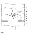
- the rotary belt scraper 20 shown in FIG. 4b has the same width as the conveyor belt 1 to be cleaned. To do what is necessary for the conveyor belt to drive it Being able to generate torque is a slight inclination the axis of rotation 17 is provided with respect to the vertical.
- the lateral angle of inclination ⁇ has the same effect trained spring means 4 'a different Contact pressure on the two sides of the conveyor belt and thereby different torques with respect to the axis 17 '.
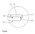
- FIG. 4c shows the detail E corresponding to FIG. 4a Structure of a wiping element 2 '.
- the wiping elements are in a scraper 2.1 'and a support arm 2.2' subdivided.
- the scrapers made of metal or rubber (2.1 ') divided into segments 18. Each segment is 18 individually by a plurality of screw connections 19 on the support arm 2.2 'attached.
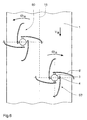
- FIG. 5 there are two rotary belt scrapers of the same design 50, 50 'in the longitudinal direction of the conveyor belt 1 offset and right or left of the longitudinal axis 15 of the Volume 1 arranged.
- the rotary belt scrapers 50, 50 ' have an opposite direction of rotation.
- the wiping elements 6 ' are arcuate and tangential hinged to the respective turret 3.
- the the Wiping elements 6 'on the supporting side of the conveyor belt 1 pressing spring means are designated 4.
- FIG. 6 has an inventive essentially according to the embodiment
- FIG. 1 shows corresponding rotary belt scrapers 30, whose axis of rotation 17 is the longitudinal axis 15 of the conveyor belt 1 cuts vertically.
- two conventional beam conveyor belt cleaners are offset 40 arranged, each from the outside of the band cover about a third of the width of the conveyor belt.
- the central, most polluted third of the conveyor belt is by the invention, tangentially via spring means 4 wiping elements articulated to a rotary head 3 2 having rotary belt scraper 30 cleaned.
- the rotary belt scraper 60 shown has one the scraper elements 2 "encompassing the bearing ring 13, the one in a crossbar 11 between the support bars 9 of the endless conveyor attached counter bearing 14 guided.
- the straight wiping elements 2 " extend from the inner edge of this bearing ring 13 radially inwards and protrude axially beyond the bearing ring 13 Direction to make the required active contact with the to be able to produce cleaning conveyor belt 1.
- the production the required contact pressure for the wiping elements 2 " is done by spring means 4", which on the Junction between bearing ring 13 and wiping element 2 "are provided.
- the drive of the rotary belt scraper 60 is done by the conveyor belt to be cleaned 1, the torque required for this by center offset or slight lateral inclination with respect to the conveyor belt - As already in the explanations for the figures 4a and 4b described - is generated.
- the rotary belt scrapers according to the invention become direct behind the discharge drum, but still before the pressure drum of the endless conveyor arranged in such a way that they are not in the ejection parabola with their periphery of the material to be conveyed.
- the smeared dirt are fed into separate feed troughs via bulk material funnels transferred.
Landscapes
- Engineering & Computer Science (AREA)
- Mechanical Engineering (AREA)
- Structure Of Belt Conveyors (AREA)
- Ignition Installations For Internal Combustion Engines (AREA)
- Valve-Gear Or Valve Arrangements (AREA)
- Holding Or Fastening Of Disk On Rotational Shaft (AREA)
- Cleaning In General (AREA)
- Belt Conveyors (AREA)
Description
- Figur 1
- eine erste bevorzugte Ausführungsform der Erfindung Draufsicht,
- Figur 2
- eine weitere günstige Ausführungsform der in Figur 1 dargestellten Erfindung in Draufsicht,
- Figur 3a bis 3c
- vorteilhafte Varianten von Abstreichelementen gemäß der Erfindung als Teildarstellungen in Draufsicht,
- Figur 4a
- das Ausführungsbeispiel gemäß Figur 2 in der Darstellung als Teilschnitt längs der Linie A...A gemäß Figur 2,
- Figur 4b
- eine Variante zu dem in Figur 4a dargestellten Ausführungsbeispiel die in Figur 2 gezeigte Weiterbildung der Erfindung in anderer Positionierung und in Darstellung entsprechend der Figur 4a,
- Figur 4c
- eine Einzelheit E gemäß Figur 4a,
- Figur 5
- eine andere günstige Ausführungsform der Erfindung in Draufsicht,
- Figur 6
- eine Variante der in Figur 5 dargestellten Ausführungsform,
- Figur 7
- eine andere vorteilhafte Ausführungsform der Erfindung in Draufsicht,
- Figur 8a
- einen Teilschnitt längs der Linie B...B der Ausführungsform gemäß Figur 7 sowie
- Figur 8b
- eine Variante der Ausführungsform gemäß Figur 8a in entsprechender Darstellung.
Claims (19)
- Rotationsbandabstreicher (10; 20; 30; 50'; 60) für ein Förderband, bestehend aus einer Anordnung mit mindestens einem, einen zum Anliegen an einem Förderband ausgebildeten Kantenbereich aufweisenden und um eine im wesentlichen senkrecht zu einer zu reinigenden Bandebene verlaufenden Drehachse rotierenden Abstreichelement (2; 2'; 2.2'; 6; 6'; 7; 8) zum Entfernen von an dem Förderband anhaftenden Verschmutzungen, wobei das Abstreichelement mindestens einen Bereich aufweist, der eine in Bezug auf die Drehachse (17; 17') im wesentlichen radial gerichtete Komponente aufweist und jedem Abstreichelement (2; 2'; 2.2'; 5; 6; 6'; 7; 8) ein Federmittel (4; 4'; 42') derart zugeordnet ist, daß das Abstreichelement (2; 2'; 2.2'; 5; 6; 6'; 7; 8) durch die Federkraft des Federmittels (4; 4'; 4.2') im wesentlichen gleichmäßig an eine zu reinigende Tragseite des Förderbandes (1) preßbar ist, dadurch gekennzeichnet, daß jedes Abstreichelement (2; 2'; 2.2'; 5; 6; 6'; 7; 8) jeweils über ein Federmittel (4) an einem Drehkopf (3) angelenkt ist.
- Rotationsbandabstreicher nach Anspruch 1, dadurch gekennzeichnet, daß das Abstreichelement zum Bilden eines Reibschlusses mit einem zu reinigenden Förderband an der Untertrumseite der Förderbandanlage in Wirkkontakt zum rotierenden Antrieb um die senkrecht zur Bandoberfläche gerichteten Drehachse ausgebildet ist, wobei quer zur Bandrichtung gesehen die Krafteinleitung an einer Seite der Drehachse überwiegt.
- Rotationsbandabstreicher nach Anspruch 2, dadurch gekennzeichnet, daß mehrere Abstreichelemente (2', 7) rotationssymmetrisch angeordnet sind.
- Rotationsbandabstreicher nach Anspruch 3, dadurch gekennzeichnet, daß die Abstreichelemente (2') die Speichen eines Rades bilden.
- Rotationsbandabstreicher nach Anspruch 1, dadurch gekennzeichnet, daß die Abstreichelemente (2, 2', 2", 6, 6', 7, 8) an einem zentrisch gelagerten Drehkopf (3, 3') und/oder an einem um die Drehachse rotierend gelagerten Ring (13) befestigt sind.
- Rotationsbandabstreicher nach Anspruch 1, dadurch gekennzeichnet, daß die Abstreichelemente (2") innerhalb eines rotierenden Ringes (13) oder Teilrings in Form eines Radreifens angeordnet sind und sich von dessen Innenseite im wesentlichen radial nach innen erstrecken.
- Rotationsbandabstreicher nach Anspruch 1, dadurch gekennzeichnet, daß die Schmalseite der Abstreichelemente (2, 2', 2", 5, 6, 6', 7, 8) der zu reinigenden Tragseite des Förderbandes (1) zugewandt ist.
- Rotationsbandabstreicher nach Anspruch 1, dadurch gekennzeichnet, daß der Drehkopf (3, 3') oder die Rotationsachse (17) der Abstreichelemente (2, 2', 2", 5, 6, 6', 7, 8) zur außermittigen Anordnung in Bezug auf eine Längsachse eines Förderbandes (1) derart ausgebildet sind, daß die Abstreichelemente das Förderband seitlich unsymmetrisch überragen.
- Rotationsbandabstreicher nach Anspruch 1, gekennzeichnet durch einen geringen lateralen Neigungswinkel α gegenüber der durch das Förderband (1) aufgespannten Ebene.
- Rotationsbandabstreicher nach Anspruch 1, dadurch gekennzeichnet, daß das Abstreichelement (5, 6, 6', 7, 8) einen mindestens einseitig gekrümmten Verlauf aufweist.
- Rotationsbandabstreicher nach Anspruch 10, dadurch gekennzeichnet, daß das Abstreichelement (5, 6, 6', 7, 8) bogen- oder S-förmig ausgebildet ist.
- Rotationsbandabstreicher nach Anspruch 1, dadurch gekennzeichnet, daß die freien Enden mehrerer Abstreichelemente (2, 2') durch Abstandshalter (5, 5') verbunden sind.
- Rotationsbandabstreicher nach Anspruch 1, dadurch gekennzeichnet, daß die Abstreichelemente (2, 2', 2") auswechsel- und/oder nachstellbar ausgestaltet sind und/oder aus einem nicht das Förderband kontaktierenden Tragarm (2.2') und einem an dem Band anliegenden Abstreichkörper (2.1'), bestehen, der nicht vollständige radiale Länge des Abstreichelements aufweist.
- Rotationsbandabstreicher nach Anspruch 1, dadurch gekennzeichnet, daß der Abstreichkörper (2.1') aus Gummi, Kunststoff oder Metall besteht.
- Rotationsbandabstreicher nach Anspruch 14, dadurch gekennzeichnet, daß im Falle der Verwendung von Kunststoff Polyurethan vorgesehen ist, während im Falle der Verwendung eines Metalls ein Hartmetallwerkstoff, insbesondere ein Werkzeugstahl mit einem oder mehreren Legierungsbestandteil(en) von Cr, Mo oder Va mit Gewichtsanteil(en) im Bereich von 0,5 bis 5 % vorgesehen ist.
- Rotationsbandabstreicher nach Anspruch 1, dadurch gekennzeichnet, daß der Abstreichkörper (2.1') aus mehreren getrennten mit dem Tragarm (2.2') lösbar verbundenen Segmenten (18) besteht.
- Rotationsbandabstreicher nach Anspruch 1, dadurch gekennzeichnet, daß mehrere Abstreichelemente unterschiedlicher radialer Erstreckung vorgesehen sind.
- Rotationsbandabstreicher nach Anspruch 1, gekennzeichnet durch hydraulische oder eine Massekraft hervorrufende Vorrichtungen zur Erzeugung des Anpreßdruckes zwischen Abstreichelement (2, 2', 2") und einer Tragseite eines Förderbandes (1) vorgesehen sind.
- Rotationsbandabstreicher nach Anspruch 1, gekennzeichnet durch mindestens einen weiteren lateral versetzt anzuordnenden Rotationsbandabstreicher (50, 50'), insbesondere mit - in Bezug auf den anderen - gegenläufiger Drehrichtung.
Applications Claiming Priority (3)
| Application Number | Priority Date | Filing Date | Title |
|---|---|---|---|
| DE19623314A DE19623314A1 (de) | 1996-06-01 | 1996-06-01 | Rotationsbandabstreicher |
| DE19623314 | 1996-06-01 | ||
| PCT/DE1997/001152 WO1997046471A1 (de) | 1996-06-01 | 1997-06-02 | Rotationsbandabstreicher |
Publications (2)
| Publication Number | Publication Date |
|---|---|
| EP0907594A1 EP0907594A1 (de) | 1999-04-14 |
| EP0907594B1 true EP0907594B1 (de) | 2002-05-08 |
Family
ID=7796658
Family Applications (1)
| Application Number | Title | Priority Date | Filing Date |
|---|---|---|---|
| EP97926987A Expired - Lifetime EP0907594B1 (de) | 1996-06-01 | 1997-06-02 | Rotationsbandabstreicher |
Country Status (4)
| Country | Link |
|---|---|
| EP (1) | EP0907594B1 (de) |
| AT (1) | ATE217291T1 (de) |
| DE (2) | DE19623314A1 (de) |
| WO (1) | WO1997046471A1 (de) |
Families Citing this family (5)
| Publication number | Priority date | Publication date | Assignee | Title |
|---|---|---|---|---|
| DE10146180B4 (de) * | 2001-09-19 | 2008-10-30 | Maschinenbau Krumscheid Gmbh | Vorrichtung zur mechanischen Reinigung eines Förderbandes |
| DE102004043549A1 (de) * | 2004-09-09 | 2006-03-30 | Daimlerchrysler Ag | Fördervorrichtung |
| CN104986544B (zh) * | 2015-05-27 | 2017-07-18 | 温州大学 | 一种砂石输送带用旋转清洁装置 |
| CN105000357B (zh) * | 2015-07-02 | 2017-12-08 | 贵州顺安机电设备有限公司 | 一种自动调节清灰装置 |
| CN109650000A (zh) * | 2019-01-21 | 2019-04-19 | 贵州盘江精煤股份有限公司 | 一种皮带机尾清扫装置及方法 |
Family Cites Families (5)
| Publication number | Priority date | Publication date | Assignee | Title |
|---|---|---|---|---|
| CH572855A5 (de) * | 1974-08-07 | 1976-02-27 | Kibag Ag | |
| DD159257A3 (de) * | 1981-05-04 | 1983-03-02 | Gerhard Kollenda | Reinigungsvorrichtung fuer foerderbaender |
| SU988701A1 (ru) * | 1981-08-14 | 1983-01-15 | Украинский научно-исследовательский и проектно-конструкторский институт по обогащению и брикетированию углей | Устройство дл очистки ленты конвейера |
| AU598683B2 (en) * | 1987-06-22 | 1990-06-28 | Arnold Industrial & Mining Supplies Pty Ltd | Cleaner conveyor belt |
| SU1694457A1 (ru) * | 1989-07-10 | 1991-11-30 | Специальное конструкторское бюро по конструированию технологического оборудования для обогащения руд "Механобр" | Устройство дл очистки ленты конвейера |
-
1996
- 1996-06-01 DE DE19623314A patent/DE19623314A1/de not_active Withdrawn
-
1997
- 1997-06-02 AT AT97926987T patent/ATE217291T1/de not_active IP Right Cessation
- 1997-06-02 DE DE59707226T patent/DE59707226D1/de not_active Expired - Fee Related
- 1997-06-02 WO PCT/DE1997/001152 patent/WO1997046471A1/de not_active Ceased
- 1997-06-02 EP EP97926987A patent/EP0907594B1/de not_active Expired - Lifetime
Also Published As
| Publication number | Publication date |
|---|---|
| DE19623314A1 (de) | 1997-12-04 |
| DE59707226D1 (de) | 2002-06-13 |
| ATE217291T1 (de) | 2002-05-15 |
| WO1997046471A1 (de) | 1997-12-11 |
| EP0907594A1 (de) | 1999-04-14 |
Similar Documents
| Publication | Publication Date | Title |
|---|---|---|
| DE3608193C2 (de) | ||
| DE3885605T2 (de) | Bandreiniger und dessen Kratzer. | |
| DE102016000619A1 (de) | Abstreifer für Gurtföderer | |
| EP0574703A1 (de) | Einrichtung zum Abbremsen von Druckprodukten in dem Auslegeschaufelrad eines Falzapparates | |
| CH648369A5 (de) | Spur- oder planiergeraet fuer ski-loipen bzw. ski-pisten. | |
| EP2495074B1 (de) | Vorrichtung zum Schleifen und/oder Bürsten von Gegenständen | |
| EP0907594B1 (de) | Rotationsbandabstreicher | |
| EP0472102B1 (de) | Vertikutierer mit auf einer Messerwelle befestigten Messerscheiben | |
| DE4328302C2 (de) | Zentrifuge | |
| DE2432361A1 (de) | Vorrichtung zum zerschneiden von holzartigen materialien in einzelne plaettchen (ii) | |
| EP0291774B1 (de) | Schneidwalzenzerkleinerer | |
| DE19508090C2 (de) | Abstreifvorrichtung zum Reinigen von Förderbändern mit einer Tragachse und mehreren darauf angeordneten Abstreiferelementen | |
| WO2010052145A1 (de) | Segmentkörper und abstreifer für einen fördergurtabstreifer | |
| DE3333985A1 (de) | Scheibenwischerblatt | |
| DE19603934C1 (de) | Abstreifleiste mit konvexer Abstreifkante | |
| DE102005055731B4 (de) | Tragrollenanordnung und Transporteinrichtung | |
| DE29803880U1 (de) | Sternrad für Sternradwalzen und Vorrichtung mit Sternradwalze | |
| DE3033490C1 (de) | Waschvorrichtung zum Waschen der Raeder eines Kraftfahrzeuges | |
| DE3742583C1 (de) | Abstreifvorrichtung fuer Foerderbaender od.dgl. | |
| DE19755997B4 (de) | Einrichtung zum Sauberhalten einer Textilfasermaterial transportierenden Walze in einer Maschine | |
| DE19859263B4 (de) | Reinigungsvorrichtung für Gurtförderer | |
| DE2118576A1 (de) | Fahrbarer Forderer | |
| DE2651206A1 (de) | Einrichtung zum saeubern von gegenstaenden, insbesondere von wurzelfruechten | |
| DE3431333A1 (de) | Bodenwalze fuer die ackerbestellung | |
| DE4239890C2 (de) | Förderbandabstreifer |
Legal Events
| Date | Code | Title | Description |
|---|---|---|---|
| PUAI | Public reference made under article 153(3) epc to a published international application that has entered the european phase |
Free format text: ORIGINAL CODE: 0009012 |
|
| 17P | Request for examination filed |
Effective date: 19981214 |
|
| AK | Designated contracting states |
Kind code of ref document: A1 Designated state(s): AT BE CH DE ES FR LI NL PT |
|
| 17Q | First examination report despatched |
Effective date: 19990720 |
|
| GRAG | Despatch of communication of intention to grant |
Free format text: ORIGINAL CODE: EPIDOS AGRA |
|
| GRAG | Despatch of communication of intention to grant |
Free format text: ORIGINAL CODE: EPIDOS AGRA |
|
| GRAH | Despatch of communication of intention to grant a patent |
Free format text: ORIGINAL CODE: EPIDOS IGRA |
|
| GRAH | Despatch of communication of intention to grant a patent |
Free format text: ORIGINAL CODE: EPIDOS IGRA |
|
| GRAA | (expected) grant |
Free format text: ORIGINAL CODE: 0009210 |
|
| AK | Designated contracting states |
Kind code of ref document: B1 Designated state(s): AT BE CH DE ES FR LI NL PT |
|
| PG25 | Lapsed in a contracting state [announced via postgrant information from national office to epo] |
Ref country code: NL Free format text: LAPSE BECAUSE OF FAILURE TO SUBMIT A TRANSLATION OF THE DESCRIPTION OR TO PAY THE FEE WITHIN THE PRESCRIBED TIME-LIMIT Effective date: 20020508 |
|
| REF | Corresponds to: |
Ref document number: 217291 Country of ref document: AT Date of ref document: 20020515 Kind code of ref document: T |
|
| REG | Reference to a national code |
Ref country code: CH Ref legal event code: EP |
|
| REF | Corresponds to: |
Ref document number: 59707226 Country of ref document: DE Date of ref document: 20020613 |
|
| PG25 | Lapsed in a contracting state [announced via postgrant information from national office to epo] |
Ref country code: PT Free format text: LAPSE BECAUSE OF FAILURE TO SUBMIT A TRANSLATION OF THE DESCRIPTION OR TO PAY THE FEE WITHIN THE PRESCRIBED TIME-LIMIT Effective date: 20020808 |
|
| REG | Reference to a national code |
Ref country code: CH Ref legal event code: NV Representative=s name: PATENTBUERO PAUL ROSENICH AG |
|
| NLV1 | Nl: lapsed or annulled due to failure to fulfill the requirements of art. 29p and 29m of the patents act | ||
| ET | Fr: translation filed | ||
| PG25 | Lapsed in a contracting state [announced via postgrant information from national office to epo] |
Ref country code: ES Free format text: LAPSE BECAUSE OF FAILURE TO SUBMIT A TRANSLATION OF THE DESCRIPTION OR TO PAY THE FEE WITHIN THE PRESCRIBED TIME-LIMIT Effective date: 20021128 |
|
| PLBE | No opposition filed within time limit |
Free format text: ORIGINAL CODE: 0009261 |
|
| STAA | Information on the status of an ep patent application or granted ep patent |
Free format text: STATUS: NO OPPOSITION FILED WITHIN TIME LIMIT |
|
| 26N | No opposition filed |
Effective date: 20030211 |
|
| PGFP | Annual fee paid to national office [announced via postgrant information from national office to epo] |
Ref country code: FR Payment date: 20030618 Year of fee payment: 7 |
|
| PGFP | Annual fee paid to national office [announced via postgrant information from national office to epo] |
Ref country code: AT Payment date: 20030624 Year of fee payment: 7 |
|
| PGFP | Annual fee paid to national office [announced via postgrant information from national office to epo] |
Ref country code: CH Payment date: 20030625 Year of fee payment: 7 |
|
| PGFP | Annual fee paid to national office [announced via postgrant information from national office to epo] |
Ref country code: BE Payment date: 20030702 Year of fee payment: 7 |
|
| PG25 | Lapsed in a contracting state [announced via postgrant information from national office to epo] |
Ref country code: AT Free format text: LAPSE BECAUSE OF NON-PAYMENT OF DUE FEES Effective date: 20040602 |
|
| PG25 | Lapsed in a contracting state [announced via postgrant information from national office to epo] |
Ref country code: LI Free format text: LAPSE BECAUSE OF NON-PAYMENT OF DUE FEES Effective date: 20040630 Ref country code: CH Free format text: LAPSE BECAUSE OF NON-PAYMENT OF DUE FEES Effective date: 20040630 Ref country code: BE Free format text: LAPSE BECAUSE OF NON-PAYMENT OF DUE FEES Effective date: 20040630 |
|
| BERE | Be: lapsed |
Owner name: INDUSTRIE- UND FORDERTECHNIK G.M.B.H. *IFT Effective date: 20040630 |
|
| REG | Reference to a national code |
Ref country code: CH Ref legal event code: PL |
|
| PG25 | Lapsed in a contracting state [announced via postgrant information from national office to epo] |
Ref country code: FR Free format text: LAPSE BECAUSE OF NON-PAYMENT OF DUE FEES Effective date: 20050228 |
|
| REG | Reference to a national code |
Ref country code: FR Ref legal event code: ST |
|
| PGFP | Annual fee paid to national office [announced via postgrant information from national office to epo] |
Ref country code: DE Payment date: 20051222 Year of fee payment: 9 |
|
| PG25 | Lapsed in a contracting state [announced via postgrant information from national office to epo] |
Ref country code: DE Free format text: LAPSE BECAUSE OF NON-PAYMENT OF DUE FEES Effective date: 20070103 |