EP0907594B1 - Rotary belt scraper - Google Patents
Rotary belt scraper Download PDFInfo
- Publication number
- EP0907594B1 EP0907594B1 EP97926987A EP97926987A EP0907594B1 EP 0907594 B1 EP0907594 B1 EP 0907594B1 EP 97926987 A EP97926987 A EP 97926987A EP 97926987 A EP97926987 A EP 97926987A EP 0907594 B1 EP0907594 B1 EP 0907594B1
- Authority
- EP
- European Patent Office
- Prior art keywords
- scraper
- belt
- rotary
- conveyor belt
- elements
- Prior art date
- Legal status (The legal status is an assumption and is not a legal conclusion. Google has not performed a legal analysis and makes no representation as to the accuracy of the status listed.)
- Expired - Lifetime
Links
- 230000000694 effects Effects 0.000 claims description 12
- 239000000463 material Substances 0.000 claims description 8
- 239000002184 metal Substances 0.000 claims description 8
- 229910052751 metal Inorganic materials 0.000 claims description 8
- 239000004033 plastic Substances 0.000 claims description 6
- 229920003023 plastic Polymers 0.000 claims description 6
- 229920001971 elastomer Polymers 0.000 claims description 5
- 239000005060 rubber Substances 0.000 claims description 5
- 229910001315 Tool steel Inorganic materials 0.000 claims description 3
- 229910045601 alloy Inorganic materials 0.000 claims description 3
- 239000000956 alloy Substances 0.000 claims description 3
- 239000007769 metal material Substances 0.000 claims description 3
- 239000004814 polyurethane Substances 0.000 claims description 3
- 229920002635 polyurethane Polymers 0.000 claims description 3
- 238000009434 installation Methods 0.000 claims description 2
- 125000006850 spacer group Chemical group 0.000 claims description 2
- 239000000470 constituent Substances 0.000 claims 1
- 230000005484 gravity Effects 0.000 claims 1
- 230000035508 accumulation Effects 0.000 abstract 1
- 238000009825 accumulation Methods 0.000 abstract 1
- 238000004140 cleaning Methods 0.000 description 22
- 230000033001 locomotion Effects 0.000 description 10
- 238000011161 development Methods 0.000 description 7
- 230000018109 developmental process Effects 0.000 description 7
- 230000002349 favourable effect Effects 0.000 description 4
- 238000003860 storage Methods 0.000 description 4
- 238000011109 contamination Methods 0.000 description 3
- 238000004519 manufacturing process Methods 0.000 description 2
- 238000007790 scraping Methods 0.000 description 2
- 230000001070 adhesive effect Effects 0.000 description 1
- 239000013590 bulk material Substances 0.000 description 1
- 238000010276 construction Methods 0.000 description 1
- 229910052500 inorganic mineral Inorganic materials 0.000 description 1
- 230000003993 interaction Effects 0.000 description 1
- 238000000034 method Methods 0.000 description 1
- 239000011707 mineral Substances 0.000 description 1
- 239000002245 particle Substances 0.000 description 1
- 230000002093 peripheral effect Effects 0.000 description 1
- 238000003825 pressing Methods 0.000 description 1
- 230000002787 reinforcement Effects 0.000 description 1
Images




Classifications
-
- B—PERFORMING OPERATIONS; TRANSPORTING
- B65—CONVEYING; PACKING; STORING; HANDLING THIN OR FILAMENTARY MATERIAL
- B65G—TRANSPORT OR STORAGE DEVICES, e.g. CONVEYORS FOR LOADING OR TIPPING, SHOP CONVEYOR SYSTEMS OR PNEUMATIC TUBE CONVEYORS
- B65G45/00—Lubricating, cleaning, or clearing devices
- B65G45/10—Cleaning devices
- B65G45/12—Cleaning devices comprising scrapers
- B65G45/14—Moving scrapers
Definitions
- the invention relates to a rotary scraper specified in the preamble of claim 1.
- Rotary belt scrapers are used to clean the support side the conveyor belts of conveyor systems, for example the Conveyor belt of an endless belt conveyor for bulk goods, used.
- rotary belt scrapers With the on the lower run side of the conveyor arranged rotary belt scrapers is multiple a better cleaning effect can be achieved than with fixed belt scraper is the case.
- rotary scraper are advantageous because with the different belt parts always changing edge areas get in touch. This will grind out Edge areas and a reduced local cleaning effect prevented.
- From US-PS 4 155 442 is a wheel-shaped rotary belt doctor previously known, which one from a band-shaped Material manufactured ring that by several extending radially inward from the inside of the ring Spokes with a central, as a fulcrum trained storage is connected.
- the ring is with its narrow side in active contact with the one to be cleaned Hinge side.
- the storage of the rotary scraper is on a traverse below the returning conveyor belt intended.
- the rotary scraper is located for the purpose of being driven by the conveyor belt with a ring edge on the side of the middle of the band in action with the Carrier side of the conveyor belt. This intervention is carried out by a slight inclination caused by the spokes of the rotary scraper spanned plane opposite the supported by the support side of the conveyor belt certain level.
- the solution for a rotary scraper described above has the disadvantage that the cleaning performance at a constant running speed of the conveyor belt and with the largest possible diameter of the spoke wheel is restricted.
- rotary tape scrapers point the way described type especially in the middle of the Tape a reduced cleaning performance, in particular, if the material to be conveyed has adhesive properties and is difficult to remove from the conveyor belt.
- the invention has the object of a rotary scraper indicate which is a simple construction with high functionality and at the same time characterized by increased cleaning performance.
- the invention includes the finding that cleaning performance a rotary scraper essentially it determines to what extent this is at least a cleaning element of the rotary belt scraper with the tape interacts.
- a traverse on the lower run of a Endless conveyor arranged rotary belt scraper several scraper elements, which as cuboid, rod or ribbon-shaped arms are formed.
- the wiping elements are essentially spoke-like according to the invention or otherwise arranged radially symmetrically in one plane, which is essentially parallel to the transport surface of the conveyor belt extends.
- the wipers are with one in the axis of rotation of the positioned turret connected so that each a narrow side of the wiping elements with the one to be cleaned Carrier side of the conveyor belt comes into contact. Thereby a particularly good wiping effect can be achieved.
- a spring means is provided, through which Spring force the scraper with essentially constant pressure against the support side to be cleaned of the conveyor belt is pressed.
- the wiping elements are rotationally symmetrical on the trained turret articulated radially extending, preferably at least three wiping elements are provided are.
- the rotary spoke scraper is caused by the differently sized frictional forces of the normal forces acting on the conveyor belt via the surface pressure of the sections of the scraper elements located to the right and left of the conveyor belt center and by the movement of the conveyor belt with the Velocity v B set in a rotary motion with the angular velocity ⁇ R.
- the size of the distance a is selected depending on the conveyor belt width and the degree of contamination of the conveyor belt.
- the free ends of the adjacent wiping elements by preferably extending in a straight line Spacers connected together. Thereby can advantageously mechanical overload the connection point between the doctor element and the turret be avoided.
- This form of the invention is preferred to be used for larger conveyor belt widths.
- the rotary belt doctor has a Wrapping elements, in one on a crossbar of the endless conveyor attached counter bearing guided, bearing ring on.
- the wipers extend from the inner edge of this bearing ring radially inwards and protrude the bearing ring in the axial direction to the required Active contact with the conveyor belt to be cleaned to be able to manufacture.
- spring means which at the junction between the bearing ring and wiping element are provided.
- the scraper elements of the rotary belt scraper are advantageously formed in two parts. You point each have a support arm and a wiper connected to it on which the active contact with the cleaning conveyor belt is produced. According to one Favorable development of the invention are those made of metal or additional wipers made of rubber divided into individual segments, which are independent of each other through several screw connections to the support arm are connected. This makes it easy to replace differently worn scrapers possible, without having to replace the entire wiping element got to.
- the scraper is made of rubber, plastic or metal there is, in the case of the use of plastic, polyurethane is provided while in the case of using a Metal is a hard metal material, especially a Tool steel with one or more alloy component (s) of Cr, Mo or Va with weight fraction (s) in the range from 0.5 to 5% is provided.
- rotary belt scrapers described above in combination with other conveyor belt cleaners, for example with a beam conveyor belt cleaner or in double Arrangement used.
- the individual conveyor belt cleaners are in a row to the side of the longitudinal axis of the conveyor belt staggered.
- the combination of rotary storage scraper / bar cleaner is particularly space-saving and enables one Installation in relatively narrow places.
- the rotary scraper which I turn in opposite directions, becomes a particularly effective cleaning effect in a favorable manner on a conveyor belt with stubborn tick marks reached.
- the rotary scraper of the above described versions allows main and Post-cleaning with one device. That is especially in the problem area (about 15% of the bandwidth on the right and left from the center of the belt in the direction of conveyance), in which reinforcement Form caking for a good cleaning effect of the rotary scraper important.
- the Rotary movement of the scraper elements and the running movement of the tape may be between the wiping element and Conveyor belt fixing mineral particles causing damage of the tape can cause, by which at a Spoke rotation through an angle of attack of 360 ° Frictional forces so stressed that they do not jam can.
- FIG. 1 shows a top view of a rotary belt scraper 10 attached below the conveyor belt 1 to be cleaned.
- the belt speed of the conveyor belt is labeled v B.
- the rotary belt scraper 10 rotates at an angular speed ⁇ R , the size of which depends on the belt speed v B and the distance a between the center line 15 of the returning belt 1 and the center line 16 or the axis of rotation 17 of the belt scraper 10.
- the lateral offset a whereby the rotary belt scraper 10 projects beyond the conveyor belt 1 on one side, leads to differently sized frictional forces between the supporting side of the conveyor belt 1 and the radially symmetrically arranged four scraper elements 2.
- the difference in frictional force is independent of the respective position of the scraper elements, so that the rotary belt scraper 10 is set in a uniform rotary motion.
- the wiping elements 2 are of the same design and have a spoke shape. You are on a rotary head 3 each articulated via a spring means 4 and extend refer to the shell of the turret in tangential Direction.
- the spring means 4 ensure a uniform pressure the narrow side of the scraper elements 2 to cleaning carrying side of the conveyor belt 1 and allow almost 100% cleaning of the carrying side of the conveyor belt.
- the wipers of the wipers are made - depending on the given by the transport goods of the belt Requirements - made of rubber, plastic or metal.
- plastic is polyurethane provided while in the case of using a metal a hard metal material, in particular a tool steel with one or more alloy component (s) of Cr, Mo or Va with weight fraction (s) in the range of 0.5 to 5% is particularly suitable.
- FIG. 2 20 The shape of a rotary belt scraper shown in Figure 2 20 demonstrates radially from the rotary head 3 ' externally extending, spoke-shaped wiping elements 2 'on.
- the three wiping elements 2 ' are also connected via spring means 4 'to a rotary head 3' and exhibit for reasons of mechanical stability a web connection 5 'at each of their free ends the wiping element arranged adjacent.
- FIGS. 3a, 3b and 3c for wiping elements 6, 7 and 8 are arched or have an S-shaped longitudinal section profile on.
- the wipers are radial ( Figures 3a and 3b) or tangential ( Figure 3c) using a spring means 4 hinged to the rotary head 3.
- Figure 2 various forms of arrangement of the rotary scraper 20 show the structure of the wiping elements 2 ' and their position in relation to the conveyor belt to be cleaned 1.
- the rotary belt doctor 20 shown in FIG. 4a is on one between two support bars of the endless conveyor extending traverse 11 under the retracting Conveyor belt 1 positioned.
- the junction 12 between Spar 9 and traverse 11 is designed as a predetermined breaking point, so that at a jam or another Form of overloading of the rotary belt scraper 20 whose support structure is separated from the final conveyor and damage to the conveyor belt can be avoided can.
- the wiping elements 2 ' are formed in two parts and divided into a doctor body 2.1 'and a support arm 2.2'. This is a convenient replacement of the mechanical heavily used scrapers 2.1 'possible, if advanced wear requires it.
- the rotary belt scraper 20 shown in FIG. 4b has the same width as the conveyor belt 1 to be cleaned. To do what is necessary for the conveyor belt to drive it Being able to generate torque is a slight inclination the axis of rotation 17 is provided with respect to the vertical.
- the lateral angle of inclination ⁇ has the same effect trained spring means 4 'a different Contact pressure on the two sides of the conveyor belt and thereby different torques with respect to the axis 17 '.
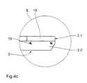
- FIG. 4c shows the detail E corresponding to FIG. 4a Structure of a wiping element 2 '.
- the wiping elements are in a scraper 2.1 'and a support arm 2.2' subdivided.
- the scrapers made of metal or rubber (2.1 ') divided into segments 18. Each segment is 18 individually by a plurality of screw connections 19 on the support arm 2.2 'attached.
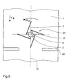
- FIG. 5 there are two rotary belt scrapers of the same design 50, 50 'in the longitudinal direction of the conveyor belt 1 offset and right or left of the longitudinal axis 15 of the Volume 1 arranged.
- the rotary belt scrapers 50, 50 ' have an opposite direction of rotation.
- the wiping elements 6 ' are arcuate and tangential hinged to the respective turret 3.
- the the Wiping elements 6 'on the supporting side of the conveyor belt 1 pressing spring means are designated 4.
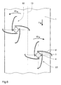
- FIG. 6 has an inventive essentially according to the embodiment
- FIG. 1 shows corresponding rotary belt scrapers 30, whose axis of rotation 17 is the longitudinal axis 15 of the conveyor belt 1 cuts vertically.
- two conventional beam conveyor belt cleaners are offset 40 arranged, each from the outside of the band cover about a third of the width of the conveyor belt.
- the central, most polluted third of the conveyor belt is by the invention, tangentially via spring means 4 wiping elements articulated to a rotary head 3 2 having rotary belt scraper 30 cleaned.
- the rotary belt scraper 60 shown has one the scraper elements 2 "encompassing the bearing ring 13, the one in a crossbar 11 between the support bars 9 of the endless conveyor attached counter bearing 14 guided.
- the straight wiping elements 2 " extend from the inner edge of this bearing ring 13 radially inwards and protrude axially beyond the bearing ring 13 Direction to make the required active contact with the to be able to produce cleaning conveyor belt 1.
- the production the required contact pressure for the wiping elements 2 " is done by spring means 4", which on the Junction between bearing ring 13 and wiping element 2 "are provided.
- the drive of the rotary belt scraper 60 is done by the conveyor belt to be cleaned 1, the torque required for this by center offset or slight lateral inclination with respect to the conveyor belt - As already in the explanations for the figures 4a and 4b described - is generated.
- the rotary belt scrapers according to the invention become direct behind the discharge drum, but still before the pressure drum of the endless conveyor arranged in such a way that they are not in the ejection parabola with their periphery of the material to be conveyed.
- the smeared dirt are fed into separate feed troughs via bulk material funnels transferred.
Landscapes
- Engineering & Computer Science (AREA)
- Mechanical Engineering (AREA)
- Structure Of Belt Conveyors (AREA)
- Valve-Gear Or Valve Arrangements (AREA)
- Holding Or Fastening Of Disk On Rotational Shaft (AREA)
- Ignition Installations For Internal Combustion Engines (AREA)
- Cleaning In General (AREA)
- Belt Conveyors (AREA)
Abstract
Description
Die Erfindung betrifft einen Rotationsbandabstreicher der
im Oberbegriff des Anspruchs 1 angegebenen Art.The invention relates to a rotary scraper
specified in the preamble of
Rotationsbandabstreicher werden zu Reinigung der Tragseite der Förderbänder von Förderanlagen, beispielsweise des Förderbandes eines Endlosgurtbandförderers für Schüttgüter, eingesetzt. Mit den an der Untertrumseite der Förderanlage angeordneten Rotationsbandabstreichern ist vielfach eine bessere Reinigungswirkung erzielbar, als es mit als feststehenden Gurtbandschabern der Fall ist. Darüberhinaus sind Rotationsbandabstreicher vorteilhaft, weil mit den unterschiedlichen Gurtteilen stets wechselnde Kantenbereiche in Kontakt kommen. Damit wird das Ausschleifen von Kantenbereichen und eine dadurch verringerte lokale Reinigungswirkung unterbunden.Rotary belt scrapers are used to clean the support side the conveyor belts of conveyor systems, for example the Conveyor belt of an endless belt conveyor for bulk goods, used. With the on the lower run side of the conveyor arranged rotary belt scrapers is multiple a better cleaning effect can be achieved than with fixed belt scraper is the case. Furthermore rotary scraper are advantageous because with the different belt parts always changing edge areas get in touch. This will grind out Edge areas and a reduced local cleaning effect prevented.
Aus der US-PS 4 155 442 ist ein radförmiger Rotationsbandabstreicher
vorbekannt, welcher einen aus einem bandförmigen
Material gefertigten Ring aufweist, der durch
mehrere, sich von der Ringinnenseite radial nach innen erstreckende
Speichen mit einer zentrischen, als Drehpunkt
ausgebildeten Lagerung verbunden ist. Der Ring steht mit
seiner Schmalseite in Wirkkontakt mit der zu reinigenden
Bandseite. Die Lagerung des Rotationsbandabstreichers ist
auf einer Traverse unterhalb des zurücklaufenden Förderbandes
vorgesehen. Der Rotationsbandabstreicher befindet
sich zwecks Antrieb durch das Förderband mit einer Ringkante
seitlich der Bandmitte in Wirkungseingriff mit der
Tragseite des Förderbandes. Dieser Eingriff wird durch eine
geringfügige Neigung der durch die Speichen des Rotationsbandabstreichers
aufgespannten Ebene gegenüber der
durch die Tragseite des Förderbandes bestimmten Ebene unterstützt. From US-
Aus den SOVIET PATENT ABSTRACTS AN 83-819053 ist ein Bandreinigungsmechanismus bekannt, der mehrere sich radial erstreckende, elastisch ausgebildete Abstreichelemente aufweist. Die elastisch ausgebildeten Abstreichelemente sind selbst starr mit einem Drehkopf verbunden. From the SOVIET PATENT ABSTRACTS AN 83-819053 is a belt cleaning mechanism known, the several radially extending, elastically designed Has wiping elements. The elastic wiping elements are itself rigidly connected to a turret.
Die vorstehend beschriebene Lösung für eine Rotationsbandabstreicher weist den Nachteil auf, daß die Reinigungsleistung bei konstanter Laufgeschwindigkeit des Förderbandes und bei größtmöglichen Durchmesser des Speichenrades eingeschränkt ist.The solution for a rotary scraper described above has the disadvantage that the cleaning performance at a constant running speed of the conveyor belt and with the largest possible diameter of the spoke wheel is restricted.
Darüber hinaus weisen Rotationsbandabstreicher des vorgehend beschriebenen Typs insbesondere im Mittenbereich des Bandes eine verminderte Reinungsleistung auf, insbesondere, wenn das Fördergut klebende Eigenschaften aufweist und sich damit nur schwer vom Förderband lösen läßt.In addition, rotary tape scrapers point the way described type especially in the middle of the Tape a reduced cleaning performance, in particular, if the material to be conveyed has adhesive properties and is difficult to remove from the conveyor belt.
Ausgehend von den Mängeln des Standes der Technik liegt der Erfindung die Aufgabe zugrunde, einen Rotationsbandabstreicher anzugeben, welcher eine einfache Konstruktion mit hoher Funktionalität aufweist und sich gleichzeitig durch eine erhöhte Reinigungsleistung auszeichnet.Based on the shortcomings of the prior art the invention has the object of a rotary scraper indicate which is a simple construction with high functionality and at the same time characterized by increased cleaning performance.
Diese Aufgabe wird durch die im Anspruch 1 angegebenen
Merkmale gelöst.This object is achieved by the specified in
Die Erfindung schließt die Erkenntnis ein, daß die Reinigungsleistung eines Rotationsbandabstreichers im wesentlichen dadurch bestimmt wird, in welchem Maße das mindestens eine Reinigungselement des Rotationsbandabstreichers mit dem Band in Wechselwirkung tritt.The invention includes the finding that cleaning performance a rotary scraper essentially it determines to what extent this is at least a cleaning element of the rotary belt scraper with the tape interacts.
Wenn nicht der Radreifen, sondern radial gerichtete Komponenten aufweisende Elemente - also praktisch die "Speichen" - eines rotierenden Rades mit dem zu reinigenden Band in Wechselwirkung treten, vergrößert sich einerseits die Zahl der wirksamen Elemente und andererseits die relative Positionionierung des jeweiligen Elements während des Eingriffs, so daß sich eine verbesserte Reinigungswirkung insbesondere schon deshalb ergibt, weil der "Anstellwinkel" der Elemente bei aufeinanderfolgenden Banddurchläufen unterschiedlich ist. Insbesondere schaben die Abstreicher mit Teilen ihrer Breitseite auch mindestens mit einer Bewegungskomponente quer zur Bandrichtung, so daß auch anhaftende Teile beseitigt werden, welche in Längsrillierungen des Bandes haften, die durch den Betrieb entstanden sind und durch übliche Abstreifer nicht beseitigt werden. Auch läßt sich durch eine radiale Bewegungskomponente zusätzlich die Relativgeschwindigkeit zwischen Abstreicher und Band erhöhen.If not the wheel tire, but radially directed components elements - practically that "Spokes" - a rotating wheel with the one to be cleaned Interaction of the band increases on the one hand the number of effective elements and, on the other hand, the relative positioning of each element during of the procedure, so that there is an improved cleaning effect in particular because the "Angle of attack" of the elements in successive Belt runs are different. In particular scraping at least the scraper with parts of their broadside with a component of motion transverse to the belt direction, so that adhering parts are removed, which in Longitudinal creases of the tape stick through the operation have arisen and are not eliminated by conventional wipers become. A radial movement component can also be used additionally the relative speed between Scraper and band increase.
Außerdem ist der relative Abstand von aufeinanderfolgenden Abstreichelementen zur Mitte des Rotationsabstreichers hin verkleinert, so daß auch insoweit eine erhöhte Reinigungswirkung erzielbar ist. Dies alles läßt sich unter der Prämisse erreichen, daß durch den stets wechselnden Kontakt mit dem Band ein Ausschleifen einzelner Bereiche der Abstreichelemente auch bei der erfindungsgemäßen Lösung vermieden ist. Insbesondere durch "Radspeicher" mit unterschiedlich angeordneten Eingriffsbereichen verschiedener Form und Länge läßt sich die Intensität der Abstreichwirkung "programmieren".In addition, the relative distance from successive Scraper elements towards the center of the rotary scraper reduced, so that an increased cleaning effect is achievable. All of this can be under the premise achieve that through the constantly changing contact grinding out individual areas of the wiping elements with the tape also avoided in the solution according to the invention is. Especially with "wheel storage" with different arranged engagement areas of different Shape and length can be the intensity of the wiping effect "program".
Entsprechend einer bevorzugten Ausführungsform der Erfindung weist der auf einer Traverse an dem Untertrum eines Endlosförderers angeordneten Rotationsbandabstreichers mehrere Abstreichelemente auf, welche als quader-, staboder bandförmige Arme ausgebildet sind. Die Abstreichelemente sind erfindungsgemäß im wesentlichen speichenartig oder in anderer Weise radialsymmetrisch in einer Ebene angeordnet, welche sich im wesentlichen parallel zur Transportfläche des Förderbandes erstreckt. According to a preferred embodiment of the invention points to a traverse on the lower run of a Endless conveyor arranged rotary belt scraper several scraper elements, which as cuboid, rod or ribbon-shaped arms are formed. The wiping elements are essentially spoke-like according to the invention or otherwise arranged radially symmetrically in one plane, which is essentially parallel to the transport surface of the conveyor belt extends.
Die Abstreichelemente sind mit einem in der Rotationsachse des positionierten Drehkopf derart verbunden, daß jeweils eine Schmalseite der Abstreichelemente mit der zu reinigenden Tragseite des Förderbandes in Kontakt tritt. Dadurch ist eine besonders gute Abstreichwirkung erreichbar.The wipers are with one in the axis of rotation of the positioned turret connected so that each a narrow side of the wiping elements with the one to be cleaned Carrier side of the conveyor belt comes into contact. Thereby a particularly good wiping effect can be achieved.
An der Verbindungsstelle zwischen Drehkopf und Abstreichelement ist jeweils ein Federmittel vorgesehen, durch dessen Federkraft das Abstreichelement mit im wesentlichen gleichbleibendem Druck gegen die zu reinigende Tragseite des Förderbandes gepreßt wird. Es sind dabei auch Einrichtungen günstig verwendbar, welche den Anpreßdruck für die Abstreichelemente hydraulisch oder durch Gewichtskräfte erzeugen.At the junction between the turret and the wiper element a spring means is provided, through which Spring force the scraper with essentially constant pressure against the support side to be cleaned of the conveyor belt is pressed. There are also facilities that can be used cheaply the contact pressure for the doctor elements hydraulically or generate by weight.
Die Abstreichelemente sind an den rotationssymmetrisch ausgebildeten Drehkopf sich radial erstreckend angelenkt, wobei vorzugsweise mindestens drei Abstreichelemente vorgesehen sind.The wiping elements are rotationally symmetrical on the trained turret articulated radially extending, preferably at least three wiping elements are provided are.
Entsprechend einer günstigen Weiterbildung der Erfindung ist eine tangentiale Anlenkung der Abstreichelemente an den Drehkopf vorgesehen.According to a favorable development of the invention is a tangential articulation of the scraper elements the turret provided.
Der Rotationsspeichenabstreicher wird bei einer asymmetrischen Anordnung des Rotationsbandabstreichers (Abstand a zwischen Förderbandmitte und Drehkopfachse) durch die unterschiedlich großen Reibungskräfte der auf das Förderband über die Flächenpressung wirkenden Normalkräfte der rechts und links von der Förderbandmitte befindlichen Abschnitte der Abstreichelemente und durch die Bewegung des Förderbandes mit der Geschwindigkeit vB in eine Drehbewegung mit der Winkelgeschwindigkeit ωR versetzt. Die Größe des Abstandes a wird in Abhängigkeit von der Förderbandbreite und dem Verschmutzungsgrad des Förderbandes gewählt.With an asymmetrical arrangement of the rotary belt scraper (distance a between the center of the conveyor belt and the rotating head axis), the rotary spoke scraper is caused by the differently sized frictional forces of the normal forces acting on the conveyor belt via the surface pressure of the sections of the scraper elements located to the right and left of the conveyor belt center and by the movement of the conveyor belt with the Velocity v B set in a rotary motion with the angular velocity ω R. The size of the distance a is selected depending on the conveyor belt width and the degree of contamination of the conveyor belt.
Bei symmetrischer Anordnung des Rotationsbandabstreichers (Abstand zwischen der Föderbandmitte und der Drehkopfachse a = Null) wird die für den Reinigungseffekt erforderliche Drehbewegung durch einseitige Erhöhung der Reibungskräfte zwischen Förderband und dem freien bzw. peripheren Ende der Abstreichelemente erreicht, indem der Drehkopf des Rotationsbandabstreichers unter einem lateralen Neigungswinkel α geringer Größe an der vorgesehenen Traverse des Förderbandgerüstes befestigt wird.With a symmetrical arrangement of the rotary belt scraper (Distance between the center of the conveyor belt and the rotating head axis a = zero) becomes the one required for the cleaning effect Rotational movement due to one-sided increase in frictional forces between the conveyor belt and the free or peripheral end of the scraper elements achieved by the rotary head of the rotary belt scraper at a lateral angle of inclination α small size on the intended crossbeam of the conveyor belt frame is attached.
Zwecks Anpassung an die Art des Fördergutes und den Grad der Verschmutzung der Tragseite des Förderbandes weisen die Abstreichelemente des Rotationsbandabsteichers entsprechend einer anderen vorteilhaften Weiterbildung der Erfindung eine mehr oder weniger stark ausgeprägte Krümmung auf. Hierbei ist eine bogen- oder S-förmige Ausgestaltung der Abstreichelemente von besonderem Vorteil.In order to adapt to the type of material to be conveyed and the degree the contamination of the carrying side of the conveyor belt the scraper elements of the rotary belt scraper accordingly another advantageous development of Invention a more or less pronounced curvature on. Here is an arc or S-shaped configuration the scraper elements are particularly advantageous.
Gemäß einer anderen bevorzugten Weiterbildung der Erfindung sind die freien Enden der benachbart angeordneten Abstreichelemente durch sich vorzugsweise geradlinig erstreckende Abstandhalter miteinander verbunden. Dadurch kann in vorteilhafter Weise eine mechanische Überbelastung der Verbindungsstelle zwischen Abstreichelement und Drehkopf vermieden werden. Diese Form der Erfindung ist vorzugsweise bei größeren Förderbandbreiten einzusetzen.According to another preferred development of the invention are the free ends of the adjacent wiping elements by preferably extending in a straight line Spacers connected together. Thereby can advantageously mechanical overload the connection point between the doctor element and the turret be avoided. This form of the invention is preferred to be used for larger conveyor belt widths.
Entsprechend einer anderen vorteilhaften Ausführungsform der Erfindung weist der Rotationsbandabstreicher einen die Abstreichelemente umgreifenden, in einem an einer Traverse des Endlosförderers befestigten Gegenlager geführten, Lagerring auf. Die Abstreichelemente erstrecken sich von dem inneren Rand dieses Lagerringes radial nach innen und überragen den Lagerring in axialer Richtung, um den erforderlichen Wirkkontakt mit dem zu reinigenden Förderband herstellen zu können. Die Erzeugung des erforderlichen Anpreßdruckes für die Abstreichelemente erfolgt - wie vorstehend bereits beschrieben - beispielsweise durch Federmittel, welche an der Verbindungsstelle zwischen Lagerring und Abstreichelement vorgesehen sind. Gleichermaßen sind geradlinig speichenförmige oder gekrümmt ausgebildete Abstreichelemente einsetzbar.According to another advantageous embodiment According to the invention, the rotary belt doctor has a Wrapping elements, in one on a crossbar of the endless conveyor attached counter bearing guided, bearing ring on. The wipers extend from the inner edge of this bearing ring radially inwards and protrude the bearing ring in the axial direction to the required Active contact with the conveyor belt to be cleaned to be able to manufacture. The generation of the required contact pressure for the wiping elements - as above already described - for example by spring means, which at the junction between the bearing ring and wiping element are provided. Are alike straight, spoke-shaped or curved scraper elements used.
Die Abstreichelemente des Rotationsbandabstreichers sind in vorteilhafter Weise zweiteilig ausgebildet. Sie weisen jeweils einen Tragarm und einen mit diesem verbundenen Abstreichkörper auf, über welchen der Wirkkontakt mit dem zu reinigenden Förderband hergestellt wird. Entsprechend einer günstigen Weiterbildung der Erfindung sind die aus Metall oder aus Gummi gefertigten Abstreichkörper zusätzlich in einzelne Segmente untergliedert, welche unabhängig voneinander durch mehrere Verschraubungen mit dem Tragarm verbunden sind. Dadurch ist ein bequemes Austauschen von unterschiedlich verschlissenen Abstreichkörpern möglich, ohne daß das gesamte Abstreichelement ausgewechselt werden muß.The scraper elements of the rotary belt scraper are advantageously formed in two parts. You point each have a support arm and a wiper connected to it on which the active contact with the cleaning conveyor belt is produced. According to one Favorable development of the invention are those made of metal or additional wipers made of rubber divided into individual segments, which are independent of each other through several screw connections to the support arm are connected. This makes it easy to replace differently worn scrapers possible, without having to replace the entire wiping element got to.
Wenn der Abstreichkörper aus Gummi, Kunststoff oder Metall besteht, ist im Falle der Verwendung von Kunststoff Polyurethan vorgesehen ist, während im Falle der Verwendung eines Metalls ein Hartmetallwerkstoff, insbesondere ein Werkzeugstahl mit einem oder mehreren Legierungsbestandteil(en) von Cr, Mo oder Va mit Gewichtsanteil(en) im Bereich von 0,5 bis 5% vorgesehen ist. If the scraper is made of rubber, plastic or metal there is, in the case of the use of plastic, polyurethane is provided while in the case of using a Metal is a hard metal material, especially a Tool steel with one or more alloy component (s) of Cr, Mo or Va with weight fraction (s) in the range from 0.5 to 5% is provided.
Entsprechend einer anderen Weiterbildung der Erfindung sind die vorstehend beschriebenen Rotationsbandabstreicher in Kombination mit anderen Förderbandreinigern, beispielsweise mit einem Balkenfördergurtreiniger oder in doppelter Anordnung eingesetzt. Die einzelenen Förderbandreiniger sind in Reihe seitlich zur Längsachse des Förderbandes versetzt angeordnet.According to another development of the invention are the rotary belt scrapers described above in combination with other conveyor belt cleaners, for example with a beam conveyor belt cleaner or in double Arrangement used. The individual conveyor belt cleaners are in a row to the side of the longitudinal axis of the conveyor belt staggered.
Die Kombination Rotationsspeicherabstreicher/Balkenreiniger ist besonders platzsparend und ermöglicht einen Einbau an relativ engen Stellen. Mit der Doppelanordnung der Rotationsbandabstreicher, welche ich gegenläufig drehen, wird in günstiger Weise ein besonders wirksamer Reinigungseffekt bei einem Förderband mit hartnäckigen Anbakkungen erreicht.The combination of rotary storage scraper / bar cleaner is particularly space-saving and enables one Installation in relatively narrow places. With the double arrangement the rotary scraper, which I turn in opposite directions, becomes a particularly effective cleaning effect in a favorable manner on a conveyor belt with stubborn tick marks reached.
Rotationsbandabstreicher gemäß der Erfindung ermöglichen eine nahezu vollständige Reinigung der Förderbänder von Verschmutzungen und am Band anhaftenden Resten des Fördergutes. Besonders in Fällen, in denen das Fördergut klebrige Eigenschaften hat und sich nur zögernd vom Förderband löst, zeigt der Rotationsspeichenabstreicher eine vorzügliche Reinigungswirkung.Allow rotary belt doctor according to the invention an almost complete cleaning of the conveyor belts from Contamination and residues of the conveyed material adhering to the belt. Especially in cases where the material is sticky Has properties and is reluctant to move off the conveyor belt solves, the rotary spoke scraper shows an excellent Cleaning effect.
Oft muß bei hartnäckigen Verschmutzungen mit Nachreinigern gearbeitet werden. Der Rotationsbandabstreicher der vorstehend beschriebenen Ausführungen ermöglicht Haupt- und Nachreinigung mit einer Vorrichtung. Das ist besonders in der Problemzone (etwa 15% der Bandbreite rechts und links von der Bandmitte in Förderrichtung), in der sich verstärkt Anbackungen bilden, für eine gute Reinigungswirkung des Rotationsbandabstreichers von Bedeutung. Durch die Drehbewegung der Abstreicherelemente und die Laufbewegung des Bandes werden sich evtl. zwischen Abstreichelement und Förderband festsetzende Mineralteilchen, die eine Beschädigung des Bandes hervorrufen können, durch die bei einer Speichenumdrehung einen Angriffswinkel von 360° durchlaufenden Reibungskräfte so beansprucht, daß sie nicht verklemmen können. Die gleichen Bewegungen sowie die gleichmäßige Anpressung auf der gesamten Länge der Abstreichelemente an das Band verhindern einen unterschiedlichen Verschleiß über die Abstreicherlänge, wie er bei Balkenreinigern in der Mitte zu verzeichnen ist. Dadurch wird ein häufiges, wartungsunfreundliches und besonders kostenintensives Nachstellen oder Nachschleifen der Abstreichelemente vermieden.Often with stubborn soiling with post-cleaners be worked. The rotary scraper of the above described versions allows main and Post-cleaning with one device. That is especially in the problem area (about 15% of the bandwidth on the right and left from the center of the belt in the direction of conveyance), in which reinforcement Form caking for a good cleaning effect of the rotary scraper important. Through the Rotary movement of the scraper elements and the running movement of the tape may be between the wiping element and Conveyor belt fixing mineral particles causing damage of the tape can cause, by which at a Spoke rotation through an angle of attack of 360 ° Frictional forces so stressed that they do not jam can. The same movements as well as the even ones Pressure along the entire length of the scraper elements on the belt prevent different wear over the scraper length, as is the case with beam cleaners is in the middle. This will make a frequent, maintenance-unfriendly and particularly cost-intensive Readjusting or regrinding the wiping elements avoided.
Andere vorteilhafte Weiterbildungen der Erfindung sind in den Unteransprüchen gekennzeichnet bzw. werden nachstehend zusammen mit der Beschreibung der bevorzugten Ausführung der Erfindung anhand der Figuren näher dargestellt. Es zeigen:
Figur 1- eine erste bevorzugte Ausführungsform der Erfindung Draufsicht,
Figur 2- eine weitere günstige Ausführungsform der in
Figur 1 dargestellten Erfindung in Draufsicht, - Figur 3a bis 3c
- vorteilhafte Varianten von Abstreichelementen gemäß der Erfindung als Teildarstellungen in Draufsicht,
- Figur 4a
- das
Ausführungsbeispiel gemäß Figur 2 in der Darstellung als Teilschnitt längs der Linie A...Agemäß Figur 2, - Figur 4b
- eine Variante zu dem in Figur 4a dargestellten
Ausführungsbeispiel die in
Figur 2 gezeigte Weiterbildung der Erfindung in anderer Positionierung und in Darstellung entsprechend der Figur 4a, - Figur 4c
- eine Einzelheit E gemäß Figur 4a,
Figur 5- eine andere günstige Ausführungsform der Erfindung in Draufsicht,
Figur 6- eine Variante der in
Figur 5 dargestellten Ausführungsform, Figur 7- eine andere vorteilhafte Ausführungsform der Erfindung in Draufsicht,
- Figur 8a
- einen Teilschnitt längs der Linie B...B der Ausführungsform gemäß Figur 7 sowie
- Figur 8b
- eine Variante der Ausführungsform gemäß Figur 8a in entsprechender Darstellung.
- Figure 1
- a first preferred embodiment of the invention top view,
- Figure 2
- 1 a further favorable embodiment of the invention shown in FIG. 1 in plan view,
- Figure 3a to 3c
- advantageous variants of wiping elements according to the invention as partial representations in top view,
- Figure 4a
- the embodiment of Figure 2 in the representation as a partial section along the line A ... A of Figure 2,
- Figure 4b
- 4a shows a variant of the exemplary embodiment shown in FIG. 4a, the further development of the invention shown in FIG. 2 in a different positioning and in a representation corresponding to FIG. 4a,
- Figure 4c
- a detail E according to Figure 4a,
- Figure 5
- another cheap embodiment of the invention in plan view,
- Figure 6
- a variant of the embodiment shown in Figure 5,
- Figure 7
- another advantageous embodiment of the invention in plan view,
- Figure 8a
- a partial section along the line B ... B of the embodiment of Figure 7 and
- Figure 8b
- a variant of the embodiment of Figure 8a in a corresponding representation.
In Figur 1 ist ein unterhalb des zu reinigenden Förderbandes
1 angebrachter Rotationsbandabstreicher 10 in Draufsicht
dargestellt. Die Bandgeschwindigkeit des Förderbandes
ist mit vB bezeichenet. Der Rotationsbandabstreicher
10 dreht sich mit einer Winkelgeschwindigkeit ωR, deren
Größe von der Bandgeschwindigkeit vB und dem Abstand a
zwischen der Mittellinie 15 des rücklaufenden Bandes 1 und
der Mittellinie 16 bzw. der Rotationsachse 17 des Bandabstreichers
10 abhängt. Der seitliche Versatz a, wodurch
der Rotationsbandabstreicher 10 das Förderband 1 einseitig
überragt, führt zu unterschiedlich großen Reibkräften zwischen
der Tragseite des Förderbandes 1 und den radialsymmetrisch
angeordneten vier Abstreichelementen 2. Die Reibkraftdifferenz
ist unabhängig von der jeweiligen Stellung
der Abstreichelemente, so daß der Rotationsbandabstreicher
10 in eine gleichmäßige Drehbewegung versetzt wird. 1 shows a top view of a
Die Abstreichelemente 2 sind gleichartig ausgebildet und
weisen eine Speichenform auf. Sie sind an einem Drehkopf 3
jeweils über ein Federmittel 4 angelenkt und erstrecken
sich bezogen auf den Mantel des Drehkopfes in tangentialer
Richtung. Die Federmittel 4 sichern ein gleichmäßiges Andrücken
der Schmalseite der Abstreichelemente 2 an die zu
reinigende Tragseite des Förderbandes 1 und ermöglichen
so eine nahezu 100%-ige Reinigung der Tragseite des Förderbandes.The
Wenn die Abstreichkörper der Abstreichelemente bestehen - je nach den durch das Transportgut des Bandes vorgegebenen Anforderungen - aus Gummi, Kunststoff oder Metall. Im Falle der Verwendung von Kunststoff ist dabei Polyurethan vorgesehen, während im Falle der Verwendung eines Metalls ein Hartmetallwerkstoff, insbesondere ein Werkzeugstahl mit einem oder mehreren Legierungsbestandteil(en) von Cr, Mo oder Va mit Gewichtsanteil(en) im Bereich von 0,5 bis 5% besonders geeignet ist.If the wipers of the wipers are made - depending on the given by the transport goods of the belt Requirements - made of rubber, plastic or metal. In the event of the use of plastic is polyurethane provided while in the case of using a metal a hard metal material, in particular a tool steel with one or more alloy component (s) of Cr, Mo or Va with weight fraction (s) in the range of 0.5 to 5% is particularly suitable.
Um eine übermäßige mechanische Belastung des Befestigungspunktes
der - bedingt durch die gewählte Breite des Förderbandes
- relativ langgestreckten Abstreichelemente 2 am
Drehkopf 3 zu vermeiden, sind die freien Enden der jeweils
benachbart angeordneten Abstreichelemente durch einen geradlinigen
Steg 5 verbunden.To avoid excessive mechanical stress on the attachment point
the - due to the selected width of the conveyor belt
- Relatively
Die in Figur 2 dargestellte Form eines Rotationsbandabstreichers
20 weist sich radial von dem Drehkopf 3' nach
außen erstreckenede, speichenförmig ausgebildete Abstreichelemente
2' auf. Die drei Abstreichelemente 2' sind
ebenfalls über Federmittel 4' mit einem Drehkopf 3' verbunden
und weisen aus Gründen der mechanischen Stabilität
an ihren freien Enden jeweils eine Stegverbindung 5' zu
dem benachbart angeordneten Abstreichelement auf. Für die
Bewegungsabläufe gelten die bereits in den Ausführungen zu
Figur 1 erläuterten Bedingungen.The shape of a rotary belt scraper shown in Figure 2
20 demonstrates radially from the rotary head 3 '
externally extending, spoke-shaped
Die in den Figuren 3a, 3b und 3c gezeigten Ausführungsformen
für Abstreichelemente 6, 7 und 8 sind bogenförmig ausgebildet
oder weisen ein S-förmiges Längsschnittprofil
auf. Die Abstreichelemente sind radial (Figuren 3a und 3b)
oder tangential (Figur 3c) unter Verwendung eines Federmittels
4 an den Drehkopf 3 angelenkt.The embodiments shown in Figures 3a, 3b and 3c
for wiping
Die in den Figuren 4a und 4b dargestellten Ansichten von
Schnitten längs der Linie A...A entsprechend Figur 2 bei
verschiedenen Formen der Anordnung des Rotationsbandabstreichers
20 zeigen den Aufbau der Abstreichelemente 2'
sowie deren Position in Bezug auf das zu reinigende Förderband
1.The views of FIGS. 4a and 4b from
Cuts along the line A ... A according to Figure 2
various forms of arrangement of the
Der in Figur 4a gezeigte Rotationsbandabstreicher 20 ist
auf einer sich zwischen zwei Stützholmen des Endlosförderers
erstreckenden Traverse 11 unter dem zurücklaufenden
Förderband 1 positioniert. Die Verbindungsstelle 12 zwischen
Holm 9 und Traverse 11 ist als Sollbruchstelle ausgebildet,
so daß bei einem Verklemmen oder einer anderen
Form der Überbelastung des Rotationsbandabstreichers 20
dessen Tragkonsruktion von dem Endlösförderer getrennt
wird und eine Beschädigung des Förderbandes vermieden werden
kann.The
Der Rotationsbandabstreicher 20 in Bezug auf die Mittelachse
des Bandes 1 um den Betrag a seitlich versetzt angeordnet,
so daß ein durch Reibschluß zwischen den Abstreichelementen
2' und dem Band 1 bewirkter Antrieb des
Rotationsbandabstreichers durch unterschiedlich große,
über die Abstreichelemente auf die Achse 17 des Drehkopfes
3' übertragene Drehmomente gesichert ist. Die Federmittel
4' erzeugen eine gleich große Anpreßkraft an die zu reinigende
Tragseite des Förderbandes 1 über die gesamte Länge
der Abstreichelemente 2'.The
Die Abstreichelemente 2' sind zweiteilig ausgebildet und
in einen Abstreichkörper 2.1' sowie einen Tragarm 2.2' untergliedert.
Dadurch ist ein bequemer Austausch der mechanisch
stark beanspruchten Abstreichkörper 2.1' möglich,
wenn ein fortgeschrittener Verschleiß dies erfordert.The
Der in Figur 4b gezeigte Rotationsbandabstreicher 20 weist
die gleiche Breite auf wie das zu reinigende Förderband 1.
Um das für den Antrieb durch das Förderband erfoderliche
Drehmoment erzeugen zu können, ist eine geringfügige Neigung
der Rotationsachse 17 gegenüber der Senkrechten vorgesehen.
Der laterale Neigungswinkel α bewirkt bei gleichartig
ausgebildeten Federmitteln 4' einen unterschiedlichen
Anpreßdruck an den beiden Förderbandseiten und dadurch
verschieden große Drehmomente bezüglich der Achse
17'.The
Figur 4c zeigt als Einzelheit E entsprechend Figur 4a den
Aufbau eines Abstreichelements 2'. Die Abstreichelemente
sind in einen Abstreichkörper 2.1' und einen Tragarm 2.2'
untergliedert. Um dem unterschiedlichen Grad des Verschleißes
entsprechend einen Austausch vornehmen zu können,
sind die aus Metall oder Gummi gefertigten Abstreichkörper
(2.1') in Segmente 18 geteilt. Jedes Segment 18 ist
einzeln durch mehrere Verschraubungen 19 an dem Tragarm
2.2' befestigt.FIG. 4c shows the detail E corresponding to FIG. 4a
Structure of a
Durch die in den Figuren 5 und 6 - in Draufsicht auf die an der Unterseite des Förderbandes vorgesehenen Rotationsbandabstreicher - dargestellten Möglichkeiten der Kombination mehrerer der erfindungsgemäß gestalteten Rotationsbandabstreicher oder eines Rotatiionsbandabstreichers mit herkömmlichen Reinigungsvorrichtungen sind verbesserte Reinigungsleistungen erzielbar.Through the in Figures 5 and 6 - in plan view of the rotary scraper provided on the underside of the conveyor belt - The possible combinations shown several of the rotary belt scrapers designed according to the invention or a rotary swab with conventional cleaning devices are improved Cleaning achievable.
Gemäß Figur 5 sind zwei gleichartig ausgebildete Rotationsbandabstreicher
50, 50' in Längsrichtung des Förderbandes
1 versetzt und rechts bzw. links der Längsachse 15 des
Bandes 1 angeordnet. Die Rotationsbandabstreicher 50, 50'
weisen eine entgegengesetzte Drehrichtung auf. Die Abstreichelemente
6' sind bogenförmig ausgebildet und tangential
an den jeweiligen Drehkopf 3 angelenkt. Die die
Abstreichelemente 6' an die Tragseite des Förderbandes 1
pressenden Federmittel sind mit 4 bezeichnet.According to FIG. 5 there are two rotary belt scrapers of the
Die in Figur 6 dargestellte Anordnung weist einen erfindungsgemäßen,
im wesentlichen der Ausführungsform gemäß
Figur 1 entsprechenden Rotationsbandabstreicher 30 auf,
dessen Drehachse 17 die Längsachse 15 des Förderbandes 1
senkrecht schneidet. In Laufrichtung des Förderbandes 1
versetzt sind zwei herkömmliche Balkenfördergurtreiniger
40 angeordnet, welche von der Bandaußenseite her jeweils
etwa ein Drittel der Breite des Förderbandes erfassen. Das
zentrale, am stärksten verschmutzte Drittel des Förderbandes
wird durch den erfindungsgemäßen, tangential über Federmittel
4 an einen Drehkopf 3 angelenkte Abstreichelemente
2 aufweisenden Rotationsbandabstreicher 30 gereinigt.The arrangement shown in FIG. 6 has an inventive
essentially according to the embodiment
FIG. 1 shows corresponding
Der in Figur 7 in Draufsicht an der Bandunterseite und in
den Figuren 8a und 8b in Ansicht eines Schnittes längs der
Linie B...B gemäß Figur 7 in unterschiedlichen Positionen
dargestellte Rotationsbandabstreicher 60 weist einen einen
die Abstreichelemente 2" umgreifenden Lagerring 13 auf,
der in einem an einer Traverse 11 zwischen den Stützholmen
9 des Endlosförderers befestigten Gegenlager 14 geführten,.
Die geradlinig ausgebildeten Abstreichelemente 2"
erstrecken sich von dem inneren Rand dieses Lagerringes 13
radial nach innen und überragen den Lagerring 13 in axialer
Richtung, um den erforderlichen Wirkkontakt mit dem zu
reinigenden Förderband 1 herstellen zu können. Die Erzeugung
des erforderlichen Anpreßdruckes für die Abstreichelemente
2" erfolgt durch Federmittel 4", welche an der
Verbindungsstelle zwischen Lagerring 13 und Abstreichelement
2" vorgesehen sind. Der Antrieb des Rotationsbandabstreichers
60 erfolgt durch das zu reinigende Förderband
1, wobei das dazu notwendige Drehmoment durch Mittenversatz
oder geringfügige laterale Neigung gegenüber dem Förderband
- wie bereits in den Erläuterungen zu den Figuren
4a und 4b beschrieben - erzeugt wird.The top view in FIG. 7 on the underside of the belt and in
Figures 8a and 8b in view of a section along the
Line B ... B according to Figure 7 in different positions
The
Die erfindungsgemäßen Rotationsbandabstreicher werden direkt hinter der Abwurftrommel, jedoch noch vor der Andrucktrommel des Endlosförderers dergestalt angeordnet, daß sie mit iherer Peripherie nicht in die Abwurfparabel des Fördergutes hineinragen. Die abgestrichenen Verschmutzungen werden über Schüttguttrichter in gesonderte Aufgabetröge überführt.The rotary belt scrapers according to the invention become direct behind the discharge drum, but still before the pressure drum of the endless conveyor arranged in such a way that they are not in the ejection parabola with their periphery of the material to be conveyed. The smeared dirt are fed into separate feed troughs via bulk material funnels transferred.
Die Erfindung beschränkt sich in ihrer Ausführung nicht auf die vorstehend angegebenen bevorzugten Ausführungsbeispiele. Vielmehr ist eine Anzahl von Varianten im Rahmen der Ansprüche denkbar.The invention is not restricted in its implementation to the preferred embodiments given above. Rather, a number of variations are within the scope of the claims conceivable.
Claims (19)
- A rotary belt scraper (10; 30; 20; 50'; 60) for a conveyor belt, comprising an arrangement with at least one scraper element (2; 2'; 2.2'; 6; 6'; 7; 8) which has an edge region for bearing against a conveyor belt and which rotates about an axis of rotation extending substantially perpendicularly to a belt plane to be cleaned, for the removal of fouling adhering to the conveyor belt, wherein the scraper element has at least one region which has a component directed substantially radially with respect to the axis of rotation (17; 17') and a spring means (4; 4'; 42') is associated with each scraper element (2; 2'; 2.2'; 5; 6; 6'; 7; 8) in such a way that the scraper element (2; 2'; 2.2'; 5; 6; 6'; 7; 8) can be pressed by the spring force of the spring means (4; 4'; 4.2') substantially uniformly against a carrier side of the conveyor belt (1), which is to be cleaned, characterised in that each scraper element (2; 2'; 2.2'; 5; 6; 6'; 7; 8) is respectively articulated by way of a spring means (4) to a rotary head (3).
- A rotary belt scraper according to claim 1 characterised in that the scraper element is adapted to form frictional engagement in operative contact with a conveyor belt to be cleaned at the lower run side of the conveyor belt installation for driving in rotation about the axis of rotation which is directed perpendicularly to the surface of the belt, wherein viewed transversely with respect to the belt direction the application of force predominates at one side of the axis of rotation.
- A rotary belt scraper according to claim 2 characterised in that a plurality of scraper elements (2', 7) are arranged in rotationally symmetrical relationship.
- A rotary belt scraper according to claim 3 characterised in that the scraper elements (2') form the spokes of a wheel.
- A rotary belt scraper according to claim 1 characterised in that the scraper elements (2; 2'; 2.2'; 5; 6; 6'; 7; 8) are fixed to a centrally mounted rotary head (3, 3') and/or to a ring (13) mounted rotatably about the axis of rotation.
- A rotary belt scraper according to claim 1 characterised in that the scraper elements (2") are arranged within a rotating ring (13) or ring portion in the form of a wheel tyre and extend from the inside thereof substantially radially inwardly.
- A rotary belt scraper according to claim 1 characterised in that the narrow side of the scraper elements (2, 2', 2", 5, 6, 6', 7, 8) faces towards the carrier side of the conveyor belt (1), which is to be cleaned.
- A rotary belt scraper according to claim 1 characterised in that the rotary head (3, 3') or the axis of rotation (17) of the scraper elements (2, 2', 2", 5, 6, 6', 7, 8) are designed for eccentric arrangement with respect to a longitudinal axis of a conveyor belt (1) in such a way that the scraper elements laterally asymmetrically project beyond the conveyor belt.
- A rotary belt scraper according to claim 1 characterised by a small lateral angle of inclination α with respect to the plane defined by the conveyor belt (1).
- A rotary belt scraper according to claim 1 characterised in that the scraper element (5, 6, 6', 7, 8) is of a configuration which is curved at least at one side.
- A rotary belt scraper according to claim 10 characterised in that the scraper element (5, 6, 6', 7, 8) is of an arcuate or S-shaped configuration.
- A rotary belt scraper according to claim 1 characterised in that the free ends of a plurality of scraper elements (2, 2') are connected by spacers (5, 5').
- A rotary belt scraper according to claim 1 characterised in that the scraper elements (2, 2', 2") are adapted to be replaceable and/or adjustable and/or comprise a carrier arm (2.2') which does not contact the conveyor belt and a scraper body (2.1') which bears against the belt and which is not of the complete radial length of the scraper element.
- A rotary belt scraper according to claim 1 characterised in that the scraper body (2.1') comprises rubber, plastic material or metal.
- A rotary belt scraper according to claim 14 characterised in that when using plastic material polyurethane is provided while when using a metal there is provided a hard metal material, in particular a tool steel with one or more alloy constituents of Cr, Mo or Va with a proportion or proportions by weight in the range of from 0.5 to 5%.
- A rotary belt scraper according to claim 1 characterised in that the scraper body (2.1') comprises a plurality of separate segments (18) releasably connected to the carrier arm (2.2').
- A rotary belt scraper according to claim 1 characterised in that there are provided a plurality of scraper elements of different radial extent.
- A rotary belt scraper according to claim 1 characterised by hydraulic devices or devices causing a force due to the effect of gravity for producing the contact pressure between a scraper element (2, 2', 2") and a carrier side of a conveyor belt (1).
- A rotary belt scraper according to claim 1 characterised by at least one further rotary belt scraper (50, 50') which is to be arranged in laterally displaced relationship, in particular with a direction of rotation which is opposite in relation to the others.
Applications Claiming Priority (3)
| Application Number | Priority Date | Filing Date | Title |
|---|---|---|---|
| DE19623314A DE19623314A1 (en) | 1996-06-01 | 1996-06-01 | Rotary belt scraper |
| DE19623314 | 1996-06-01 | ||
| PCT/DE1997/001152 WO1997046471A1 (en) | 1996-06-01 | 1997-06-02 | Rotary belt scraper |
Publications (2)
| Publication Number | Publication Date |
|---|---|
| EP0907594A1 EP0907594A1 (en) | 1999-04-14 |
| EP0907594B1 true EP0907594B1 (en) | 2002-05-08 |
Family
ID=7796658
Family Applications (1)
| Application Number | Title | Priority Date | Filing Date |
|---|---|---|---|
| EP97926987A Expired - Lifetime EP0907594B1 (en) | 1996-06-01 | 1997-06-02 | Rotary belt scraper |
Country Status (4)
| Country | Link |
|---|---|
| EP (1) | EP0907594B1 (en) |
| AT (1) | ATE217291T1 (en) |
| DE (2) | DE19623314A1 (en) |
| WO (1) | WO1997046471A1 (en) |
Families Citing this family (5)
| Publication number | Priority date | Publication date | Assignee | Title |
|---|---|---|---|---|
| DE10146180B4 (en) * | 2001-09-19 | 2008-10-30 | Maschinenbau Krumscheid Gmbh | Device for the mechanical cleaning of a conveyor belt |
| DE102004043549A1 (en) * | 2004-09-09 | 2006-03-30 | Daimlerchrysler Ag | Cleaning unit for conveyor belts comprises rotating brush with ring of bristles which fits against upper surface of belt, friction wheel mounted inside ring being driven by belt so that brush rotates |
| CN104986544B (en) * | 2015-05-27 | 2017-07-18 | 温州大学 | A kind of sandstone rotating cleaning device used for conveyer belt |
| CN105000357B (en) * | 2015-07-02 | 2017-12-08 | 贵州顺安机电设备有限公司 | One kind automatically adjusts deashing device |
| CN109650000A (en) * | 2019-01-21 | 2019-04-19 | 贵州盘江精煤股份有限公司 | A kind of belt machine end clearing apparatus and method |
Family Cites Families (5)
| Publication number | Priority date | Publication date | Assignee | Title |
|---|---|---|---|---|
| CH572855A5 (en) * | 1974-08-07 | 1976-02-27 | Kibag Ag | |
| DD159257A3 (en) * | 1981-05-04 | 1983-03-02 | Gerhard Kollenda | CLEANING DEVICE FOR FOUNDERS |
| SU988701A1 (en) * | 1981-08-14 | 1983-01-15 | Украинский научно-исследовательский и проектно-конструкторский институт по обогащению и брикетированию углей | Apparatus for cleaning conveyer belt |
| AU598683B2 (en) * | 1987-06-22 | 1990-06-28 | Arnold Industrial & Mining Supplies Pty Ltd | Cleaner conveyor belt |
| SU1694457A1 (en) * | 1989-07-10 | 1991-11-30 | Специальное конструкторское бюро по конструированию технологического оборудования для обогащения руд "Механобр" | Device for cleaning conveyer belt |
-
1996
- 1996-06-01 DE DE19623314A patent/DE19623314A1/en not_active Withdrawn
-
1997
- 1997-06-02 AT AT97926987T patent/ATE217291T1/en not_active IP Right Cessation
- 1997-06-02 WO PCT/DE1997/001152 patent/WO1997046471A1/en not_active Ceased
- 1997-06-02 DE DE59707226T patent/DE59707226D1/en not_active Expired - Fee Related
- 1997-06-02 EP EP97926987A patent/EP0907594B1/en not_active Expired - Lifetime
Also Published As
| Publication number | Publication date |
|---|---|
| ATE217291T1 (en) | 2002-05-15 |
| WO1997046471A1 (en) | 1997-12-11 |
| EP0907594A1 (en) | 1999-04-14 |
| DE59707226D1 (en) | 2002-06-13 |
| DE19623314A1 (en) | 1997-12-04 |
Similar Documents
| Publication | Publication Date | Title |
|---|---|---|
| DE3608193C2 (en) | ||
| DE3885605T2 (en) | Belt cleaner and its scratches. | |
| DE102016000619A1 (en) | Scrapers for belt conveyors | |
| EP0574703A1 (en) | Device for braking printed products in a delivery bucket wheel of a folding apparatus | |
| CH648369A5 (en) | TRACKING OR PLANING DEVICE FOR SKI COUNTRIES OR SKI SLOPES. | |
| EP2495074B1 (en) | Device for grinding and/or brushing objects | |
| DE4328302C2 (en) | centrifuge | |
| EP0472102B1 (en) | Scarifier with blade disks fixed on a shaft | |
| DE4112382A1 (en) | Floor or road sweeper with brush roller or plate - has angled bristle ends, and self-cleaning guide plates, with adjustable positioned rollers | |
| DE2432361A1 (en) | DEVICE FOR CUTTING WOOD-LIKE MATERIALS INTO INDIVIDUAL PLAETS (II) | |
| EP0291774B1 (en) | Shredder with rotating knives | |
| DE19508090C2 (en) | Scraper device for cleaning conveyor belts with a supporting axis and several scraper elements arranged on it | |
| WO2010052145A1 (en) | Segment body and scraper for a conveyor belt scraper | |
| DE3333985A1 (en) | WIPER BLADE | |
| DE2656913B2 (en) | Separating device for potato harvesters | |
| EP0907594A1 (en) | Rotary belt scraper | |
| DE19603934C1 (en) | Strip for scraping conveyed material from lower belt part of conveyor belt | |
| DE102005055731B4 (en) | Carrier roller arrangement and transport device | |
| DE29803880U1 (en) | Star wheel for star wheel rollers and device with star wheel roller | |
| DE3033490C1 (en) | Washing device for washing the wheels of a motor vehicle | |
| DE3742583C1 (en) | Scraper device for conveyor belts or the like. | |
| DE19755997B4 (en) | Device for keeping a textile fiber transporting roller clean in a machine | |
| DE2118576A1 (en) | Mobile conveyor | |
| DE20213358U1 (en) | Cleaner for conveyed goods and conveyor belts has carrier attached to frame with supports for hubs carrying scraper rotor with cleaning fingers | |
| DE2651206A1 (en) | EQUIPMENT FOR CLEANING OBJECTS, IN PARTICULAR ROOT FRUITS |
Legal Events
| Date | Code | Title | Description |
|---|---|---|---|
| PUAI | Public reference made under article 153(3) epc to a published international application that has entered the european phase |
Free format text: ORIGINAL CODE: 0009012 |
|
| 17P | Request for examination filed |
Effective date: 19981214 |
|
| AK | Designated contracting states |
Kind code of ref document: A1 Designated state(s): AT BE CH DE ES FR LI NL PT |
|
| 17Q | First examination report despatched |
Effective date: 19990720 |
|
| GRAG | Despatch of communication of intention to grant |
Free format text: ORIGINAL CODE: EPIDOS AGRA |
|
| GRAG | Despatch of communication of intention to grant |
Free format text: ORIGINAL CODE: EPIDOS AGRA |
|
| GRAH | Despatch of communication of intention to grant a patent |
Free format text: ORIGINAL CODE: EPIDOS IGRA |
|
| GRAH | Despatch of communication of intention to grant a patent |
Free format text: ORIGINAL CODE: EPIDOS IGRA |
|
| GRAA | (expected) grant |
Free format text: ORIGINAL CODE: 0009210 |
|
| AK | Designated contracting states |
Kind code of ref document: B1 Designated state(s): AT BE CH DE ES FR LI NL PT |
|
| PG25 | Lapsed in a contracting state [announced via postgrant information from national office to epo] |
Ref country code: NL Free format text: LAPSE BECAUSE OF FAILURE TO SUBMIT A TRANSLATION OF THE DESCRIPTION OR TO PAY THE FEE WITHIN THE PRESCRIBED TIME-LIMIT Effective date: 20020508 |
|
| REF | Corresponds to: |
Ref document number: 217291 Country of ref document: AT Date of ref document: 20020515 Kind code of ref document: T |
|
| REG | Reference to a national code |
Ref country code: CH Ref legal event code: EP |
|
| REF | Corresponds to: |
Ref document number: 59707226 Country of ref document: DE Date of ref document: 20020613 |
|
| PG25 | Lapsed in a contracting state [announced via postgrant information from national office to epo] |
Ref country code: PT Free format text: LAPSE BECAUSE OF FAILURE TO SUBMIT A TRANSLATION OF THE DESCRIPTION OR TO PAY THE FEE WITHIN THE PRESCRIBED TIME-LIMIT Effective date: 20020808 |
|
| REG | Reference to a national code |
Ref country code: CH Ref legal event code: NV Representative=s name: PATENTBUERO PAUL ROSENICH AG |
|
| NLV1 | Nl: lapsed or annulled due to failure to fulfill the requirements of art. 29p and 29m of the patents act | ||
| ET | Fr: translation filed | ||
| PG25 | Lapsed in a contracting state [announced via postgrant information from national office to epo] |
Ref country code: ES Free format text: LAPSE BECAUSE OF FAILURE TO SUBMIT A TRANSLATION OF THE DESCRIPTION OR TO PAY THE FEE WITHIN THE PRESCRIBED TIME-LIMIT Effective date: 20021128 |
|
| PLBE | No opposition filed within time limit |
Free format text: ORIGINAL CODE: 0009261 |
|
| STAA | Information on the status of an ep patent application or granted ep patent |
Free format text: STATUS: NO OPPOSITION FILED WITHIN TIME LIMIT |
|
| 26N | No opposition filed |
Effective date: 20030211 |
|
| PGFP | Annual fee paid to national office [announced via postgrant information from national office to epo] |
Ref country code: FR Payment date: 20030618 Year of fee payment: 7 |
|
| PGFP | Annual fee paid to national office [announced via postgrant information from national office to epo] |
Ref country code: AT Payment date: 20030624 Year of fee payment: 7 |
|
| PGFP | Annual fee paid to national office [announced via postgrant information from national office to epo] |
Ref country code: CH Payment date: 20030625 Year of fee payment: 7 |
|
| PGFP | Annual fee paid to national office [announced via postgrant information from national office to epo] |
Ref country code: BE Payment date: 20030702 Year of fee payment: 7 |
|
| PG25 | Lapsed in a contracting state [announced via postgrant information from national office to epo] |
Ref country code: AT Free format text: LAPSE BECAUSE OF NON-PAYMENT OF DUE FEES Effective date: 20040602 |
|
| PG25 | Lapsed in a contracting state [announced via postgrant information from national office to epo] |
Ref country code: LI Free format text: LAPSE BECAUSE OF NON-PAYMENT OF DUE FEES Effective date: 20040630 Ref country code: CH Free format text: LAPSE BECAUSE OF NON-PAYMENT OF DUE FEES Effective date: 20040630 Ref country code: BE Free format text: LAPSE BECAUSE OF NON-PAYMENT OF DUE FEES Effective date: 20040630 |
|
| BERE | Be: lapsed |
Owner name: INDUSTRIE- UND FORDERTECHNIK G.M.B.H. *IFT Effective date: 20040630 |
|
| REG | Reference to a national code |
Ref country code: CH Ref legal event code: PL |
|
| PG25 | Lapsed in a contracting state [announced via postgrant information from national office to epo] |
Ref country code: FR Free format text: LAPSE BECAUSE OF NON-PAYMENT OF DUE FEES Effective date: 20050228 |
|
| REG | Reference to a national code |
Ref country code: FR Ref legal event code: ST |
|
| PGFP | Annual fee paid to national office [announced via postgrant information from national office to epo] |
Ref country code: DE Payment date: 20051222 Year of fee payment: 9 |
|
| PG25 | Lapsed in a contracting state [announced via postgrant information from national office to epo] |
Ref country code: DE Free format text: LAPSE BECAUSE OF NON-PAYMENT OF DUE FEES Effective date: 20070103 |