EP0907066B1 - Dispositif de mesure d'angles - Google Patents
Dispositif de mesure d'angles Download PDFInfo
- Publication number
- EP0907066B1 EP0907066B1 EP98116516A EP98116516A EP0907066B1 EP 0907066 B1 EP0907066 B1 EP 0907066B1 EP 98116516 A EP98116516 A EP 98116516A EP 98116516 A EP98116516 A EP 98116516A EP 0907066 B1 EP0907066 B1 EP 0907066B1
- Authority
- EP
- European Patent Office
- Prior art keywords
- measuring device
- angle measuring
- limb
- limbs
- rotor
- Prior art date
- Legal status (The legal status is an assumption and is not a legal conclusion. Google has not performed a legal analysis and makes no representation as to the accuracy of the status listed.)
- Expired - Lifetime
Links
- 238000011156 evaluation Methods 0.000 claims description 3
- 230000004888 barrier function Effects 0.000 claims description 2
- 238000005259 measurement Methods 0.000 description 4
- 241000238633 Odonata Species 0.000 description 3
- 238000004519 manufacturing process Methods 0.000 description 2
- 230000004308 accommodation Effects 0.000 description 1
- 230000015572 biosynthetic process Effects 0.000 description 1
- 230000001419 dependent effect Effects 0.000 description 1
- 238000001514 detection method Methods 0.000 description 1
- 230000002035 prolonged effect Effects 0.000 description 1
Images


Classifications
-
- G—PHYSICS
- G01—MEASURING; TESTING
- G01B—MEASURING LENGTH, THICKNESS OR SIMILAR LINEAR DIMENSIONS; MEASURING ANGLES; MEASURING AREAS; MEASURING IRREGULARITIES OF SURFACES OR CONTOURS
- G01B5/00—Measuring arrangements characterised by the use of mechanical techniques
- G01B5/24—Measuring arrangements characterised by the use of mechanical techniques for measuring angles or tapers; for testing the alignment of axes
Definitions
- the invention relates to an angle measuring device according to the preamble of claim 1. It is already an angle measuring device known (DE-U-89 02 987.9) having two pivotable about a common pivot axis relative to each other leg, which are coupled together via a potentiometer, which allows the measurement of the included angle between the legs.
- the potentiometric measurement of the angle is subject to errors that are above a desired angular resolution in the 0.1 ° range.
- an angle measuring device (DE 297 03 041 U1), which is equipped with two rotationally coupled, to be driven rotating disks, which cooperate with each schenkelfesten sensors.
- Drive shaft and sensors are mounted at different angles in this angle, which brings an increased measurement inaccuracy with it.
- the provision of two discs with associated Sensor technology is also expensive and therefore expensive to manufacture.
- the large space required in the known angle measuring makes the placement of the drive of the discs within a pivot joint of the legs impossible. As a result, the removal of an angle set between the legs or the application of the legs to an angle to be determined is made more difficult.
- the mutual storage of the legs via three arranged in a plane bearings, the production-related ensure sufficient concentricity of the legs.
- the angle measuring device with the features of claim 1 has the advantage of enabling a cost-effective angle measurement with high accuracy.
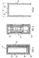
- FIG. 1 shows a view of the angle measuring device according to the invention
- Figure 2 is a section along line II-II in Figure 1
- Figure 3 is a perspective view of a rotor of Figure 2
- Figure 3a a Partial view of the rotor
- Figure 4 is a section along line IV-IV in Figure 1
- Figure 5 is a section along line VV in Figure 1
- Figure 6 is a section along line VI-VI in Figure 1 ..
- 10 denotes an angle measuring device which has a first leg 11 and a second leg 12.
- the legs 11 and 12 are pivotally mounted about a joint 13 about a common pivot axis 14 relative to each other.
- the first leg 11 is formed as a rectangular hollow profile 11a and the second leg 12 as a U-profile 12a.
- An open side of the U-profile 12a is facing the hollow profile 11a such that the hollow profile 12a is received by the U-profile 12a in a Einklapp ein of the Winkelmeß réelles 10 in itself.
- a display device 17 for displaying angle values and function keys 18 for the input of commands is housed.
- a battery housing 19 for receiving dashed lines indicated batteries or battery cells 20 and coupled to the display device 17 evaluation 21.
- the components 17 to 21 are assembled into a mounting unit 23 and in a second leg 12 out U-shaped recess in the first leg 11 is inserted.
- the battery housing 19 is closed by means of a lid 25 which is articulated in a housing 26 of the mounting unit 23 and locked to close the battery case 19 to the housing 26.
- first leg 11 In the first leg 11 are also spirit level dragonflies 28, 29 for vertical and horizontal alignment of the first leg 11.
- the dragonflies 28, 29 are matched to a first bearing surface 30 on the first leg 11, which is parallel to an inner bearing surface 31.
- a through hole 32 extends through the first leg 11 in the transverse direction parallel to the pivot axis 14.
- the U-shaped second leg 12 has in its two parallel side surfaces on various window-shaped viewing recesses.
- a first viewing window 34 allows the reading of the display device 17 and the operation of the function keys 18 in the Einklapp ein.
- a second viewing window 35 allows in this position the view of the dragonfly 29.
- a window 36 is aligned in the Einklapp ein with the through hole 32, so that the angle measuring device 10 in the Einklapp ein z. can be hung on a wall hook.
- the joint 13 is shown in more detail.
- a base body 40 by screws 41 (Figure 1) is attached.
- the base body 40 forms in the region of the joint 13 a cylindrical receptacle 42, in which a bearing part 43 is inserted centrally and fixed by means of fastening screws 44.
- the bearing part 43 is hollow-cylindrical. Inwardly to the bearing part 43 forms a pot bottom 57. With its outer periphery 45, the bearing part 43 forms a bearing receptacle 46th
- the bearing receptacle 46 is concentric with the pivot axis 14 and supports a pivot arm 47 via a sliding bush 48 on the bearing part 43.
- the pivot arm 47 is rotatably connected to the first leg 11.
- the slide bush 48 is axially secured via a slide ring 49 and a snap ring 50 on the bearing part 43.
- a not shown spring washer or disc spring between snap ring 50 and slide bushing 48 provides for the compensation of the axial play and for the desired torsional resistance between the legs 11, 12th
- the bearing part 43 receives in its central cavity 51 an electric drive motor 52.
- the drive motor 52 has a drive shaft 53 which is concentric with the pivot axis 14.
- the drive shaft 53 protrudes from a cylindrical bearing projection 55 which is formed by the housing of the drive motor 52 and is aligned by engagement with a concentric bore 56 in the bottom 57 of the bearing part 43 with the pivot axis 14 in alignment.
- Drive motor 52 and drive shaft 53 form drive means 54 for a rotor 64.
- a pivot support 58 is rotatably mounted, which is rotationally coupled to the first leg 11.
- Another carrier 59 is fixedly connected via a retaining screw 60 with the bearing part 43 and thus rotatably disposed on the second leg 12.
- Swivel support 58 and support 59 each carry a sensor 61, 62.
- the sensors 61, 62 formed by light barriers, but it can also find other non-contact sensors such as Hall sensors use.
- the rotor 64 On the drive shaft 53, the rotor 64 is arranged rotationally fixed.
- the rotor 64 is formed as a circular disc, to the radially outside of a nose 65 is formed.
- the rotor 64 For attachment to the drive shaft 53, the rotor 64 is provided with a hub 66.
- the hub 66 is connected to the disk-shaped part of the rotor 64 via ribs 67.
- a compensating bore 68 In the disk-shaped part is provided between the nose 65 and the pivot axis 14 a compensating bore 68, by means of which a conditional by the nose 65 unbalance is compensated.
- the nose 65 is shown, which is arranged on the outer circumference of the Rotos 64.
- the nose 65 has an interrupting edge 65a, which extends at least in the region of the overlap with the sensors 61, 62 along a radial ray 14a passing through the pivot axis 14. In this way, the interruption is independent of tolerances with respect to the distance of pivot axis 14 and nose 65th
- the hinge 13 is covered by the first leg 11 by means of a first cover 70 and the side of the second leg 12 by a cover 71.
- the drive motor 52 is connected via not shown leads to the batteries 20.
- the joint 13 is formed so compact that it lies within a width B of the second leg 12, resulting in very good application properties for the angle measuring device 10.
- FIG. 6 shows the U-profile of the second leg 12 receiving the first leg 11.
- the function of the angle measuring device is as follows: For measuring the angle, the rotor 64 is rotated by the drive means 54. In this case, the sensors 61, 62 are traversed periodically by the interrupting edge 65a of the nose 65. The sensors 61, 62 generate during passage of the nose 65 each signal level changes, which are detected in the evaluation device 21, preferably by means of electronic counters and converted into angular values. By detecting the transit time between the passage of the sensors 61, 62 and the detection of the circulation time to the renewed Passing the respective sensor 61, 62 can form an angular ratio, which is independent of speed fluctuations between different passes. The corresponding angular ratio is multiplied by a constant angle size, eg 360 °, and output in the display device 17.
- a constant angle size eg 360 °
Landscapes
- Physics & Mathematics (AREA)
- General Physics & Mathematics (AREA)
- Length Measuring Devices With Unspecified Measuring Means (AREA)
- A Measuring Device Byusing Mechanical Method (AREA)
Claims (14)
- Appareil de mesure angulaire comportant :- au moins deux branches (11, 12) montées dans une articulation (13) autour d'un axe de pivotement (14) commun de manière à pivoter l'une par rapport à l'autre.- au moins un rotor (64) qui, par l'intermédiaire de moyens d'entraînement (54), peut être entraîné en tournant autour d'un axe de rotation aligné avec l'axe de pivotement (14),- des points de référence (61, 62) associés aux branches (11, 12) et- sur chaque rotor (64) au moins une marque de référence (65) qui tourne avec lui et qui parcourt les points de référence (61, 62) sur une trajectoire périphérique,
caractérisé en ce que
l'articulation (13) a une partie de palier (43) centrale reliée fixemement à l'une des branches (12) ainsi qu'un logement de palier (46) concentrique par rapport à l'axe de pivotement (14) et destiné à l'autre ou aux autres branches (11). - Appareil de mesure angulaire selon la revendication 1.
caractérisé en ce que
la partie de palier (43) est cylindrique creuse, de préférence en forme de creuset, et reçoit en elle au moins partiellement les moyens d'entraînement (54), le logement de palier (46) destiné à l'autre branche (11) étant prévu sur le pourtour extérieur de la partie de palier (43). - Appareil de mesure angulaire selon la revendication 2,
caractérisé en ce que
les moyens d'entraînement (54) comportent un moteur d'entraînement (52) muni d'une saillie de palier (55) qui est concentrique à un axe de rotation d'un arbre d'entraînement (53) du moteur d'entraînement (52) et qui pénètre dans un perçage (56) situé dans un fond de creuset (57) de la partie de palier (43) et concentrique à l'axe de pivotement (14). - Appareil de mesure angulaire selon l'une des revendications précédentes,
caractérisé en ce que
une première branche (11) est un profilé creux (11a) carré et une deuxième branche (12) est un profilé en U (12a), le profilé en U (12a) recevant le profilé creux (11a) lorsque l'appareil de mesure angulaire (10) est en position repliée. - Appareil de mesure angulaire selon la revendication 4,
caractérisé en ce que
chaque branche (11. 12) présente au moins un trou de passage (32, 36) qui coïncide avec le trou de passage correspondant dans l'autre branche (11, 12) respective lorsque l'appareil de mesure angulaire (10) est en position repliée. - Appareil de mesure angulaire selon l'une des revendications précédentes,
caractérisé en ce que
les points de référence (61, 62) de différentes branches (11, 12) sont disposés de telle manière qu'ils sont successivement parcourus par la marque de référence (65) du même rotor (64). - Appareil de mesure angulaire selon l'une des revendications 1 à 6.
caractérisé en ce que
des capteurs servent de points de référence (61, 62) sur les branches. - Appareil de mesure angulaire selon la revendication 7,
caractérisé en ce que
les capteurs (61, 62) sont formés par des barrières lumineuses fourchues et la marque de référence côté rotor est formée par un bec (65) proéminent sur le pourtour du rotor (34). - Appareil de mesure angulaire selon la revendication 8,
caractérisé en ce que
le bec (65) comporte une arête d'arrêt formée au moins en partie le long d'un rayon radial qui passe par l'axe de pivotement (14). - Appareil de mesure angulaire selon la revendication 9,
caractérisé en ce que
le rotor (64) est pratiquement un disque muni d'un perçage de compensation (68) radial entre le bec (65) et l'axe de pivotement (14) afin de compenser le déséquilibre. - Appareil de mesure angulaire selon la revendication 7 ou 8,
caractérisé en ce que
la partie de palier (43) reçoit un support pivotant (58), concentrique à l'axe de rotation (14), qui est couplé par combinaison de rotation à une première branche (11) et qui porte un capteur (61) associé à cette branche (11). - Appareil de mesure angulaire selon la revendication 7, 8 ou 11.
caractérisé en ce que un support (59) qui porte un capteur (62) associé à la deuxième branche (12) est monté sur la partie de palier (43) de façon à ne pas tourner. - Appareil de mesure angulaire selon l'une des revendications précédentes,
caractérisé en ce que
les branches (11, 12) comportent des surfaces de mesure (11b, 12b) latérales et, décalées de 90° par rapport à elles, des surfaces d'appui (11c, 12c) munies de nervures (74) en saillie vers l'extérieur. - Appareil de mesure angulaire selon l'une des revendications précédentes,
caractérisé en ce que une installation d'exploitation (21) ainsi qu'un dispositif d'affichage (17) et des touches de fonction (18) sont placés dans une des branches (11, 12) et, rassemblés en une unité de montage (23), sont introduits dans la branche (11, 12) respective.
Applications Claiming Priority (2)
| Application Number | Priority Date | Filing Date | Title |
|---|---|---|---|
| DE19743568 | 1997-10-02 | ||
| DE19743568A DE19743568A1 (de) | 1997-10-02 | 1997-10-02 | Winkelmeßgerät |
Publications (3)
| Publication Number | Publication Date |
|---|---|
| EP0907066A2 EP0907066A2 (fr) | 1999-04-07 |
| EP0907066A3 EP0907066A3 (fr) | 2000-10-18 |
| EP0907066B1 true EP0907066B1 (fr) | 2006-01-04 |
Family
ID=7844388
Family Applications (1)
| Application Number | Title | Priority Date | Filing Date |
|---|---|---|---|
| EP98116516A Expired - Lifetime EP0907066B1 (fr) | 1997-10-02 | 1998-09-01 | Dispositif de mesure d'angles |
Country Status (3)
| Country | Link |
|---|---|
| US (1) | US6104480A (fr) |
| EP (1) | EP0907066B1 (fr) |
| DE (2) | DE19743568A1 (fr) |
Families Citing this family (20)
| Publication number | Priority date | Publication date | Assignee | Title |
|---|---|---|---|---|
| US6240649B1 (en) * | 1999-06-10 | 2001-06-05 | Mcelroy Paul T. | Sighting assembly |
| US20040215387A1 (en) | 2002-02-14 | 2004-10-28 | Matsushita Electric Industrial Co., Ltd. | Method for transmitting location information on a digital map, apparatus for implementing the method, and traffic information provision/reception system |
| JP3481168B2 (ja) | 1999-08-27 | 2003-12-22 | 松下電器産業株式会社 | デジタル地図の位置情報伝達方法 |
| JP5041638B2 (ja) | 2000-12-08 | 2012-10-03 | パナソニック株式会社 | デジタル地図の位置情報伝達方法とそれに使用する装置 |
| AU1501001A (en) * | 2001-01-16 | 2002-07-18 | Montenegro, Maria | An apparatus for measuring angles |
| JP4663136B2 (ja) | 2001-01-29 | 2011-03-30 | パナソニック株式会社 | デジタル地図の位置情報伝達方法と装置 |
| JP4749594B2 (ja) * | 2001-04-27 | 2011-08-17 | パナソニック株式会社 | デジタル地図の位置情報伝達方法 |
| JP4230132B2 (ja) | 2001-05-01 | 2009-02-25 | パナソニック株式会社 | デジタル地図の形状ベクトルの符号化方法と位置情報伝達方法とそれを実施する装置 |
| USD493734S1 (en) | 2002-12-03 | 2004-08-03 | Merle R. Ellis | Angle measuring device |
| DE102005059538B4 (de) * | 2005-12-13 | 2018-08-23 | Asm Automation Sensorik Messtechnik Gmbh | Scharnier-Sensor |
| US7472489B2 (en) * | 2006-03-10 | 2009-01-06 | Curtis Douglas Frank | Rowing device, digital pitch meter and other devices |
| US20070283587A1 (en) * | 2006-06-08 | 2007-12-13 | John Cerwin | Angle measuring device |
| US7726034B2 (en) * | 2007-03-09 | 2010-06-01 | Barry Douglas Wixey | Digital protractor |
| DE102008008846A1 (de) | 2008-02-13 | 2009-09-17 | Robert Bosch Gmbh | Messwerkzeug |
| CN201247026Y (zh) * | 2008-08-22 | 2009-05-27 | 桂林市晶瑞传感技术有限公司 | 多功能数显角度尺 |
| TWM378845U (en) * | 2009-12-14 | 2010-04-21 | Jin-Yi Gao | Projection type angle square |
| AT511462B1 (de) * | 2011-06-24 | 2012-12-15 | Trumpf Maschinen Austria Gmbh | Messvorrichtung für biegewerkstücke |
| US10377611B2 (en) | 2016-10-28 | 2019-08-13 | Advance Lifts, Inc. | Scissors lift with height sensor system |
| US11497592B2 (en) * | 2017-04-28 | 2022-11-15 | Universidad De La Frontera | Instrument for in situ measurement of the angle of convergence in a dental preparation |
| USD995325S1 (en) * | 2022-01-20 | 2023-08-15 | Jeremy Cooper | Level and angle finder tool |
Family Cites Families (8)
| Publication number | Priority date | Publication date | Assignee | Title |
|---|---|---|---|---|
| US4513512A (en) * | 1982-07-02 | 1985-04-30 | Nestle & Fischer | Angle-measuring instrument having an indicator for the degree of angle |
| JPS608811U (ja) * | 1983-06-29 | 1985-01-22 | 旭光学工業株式会社 | 角度測定装置 |
| FR2558950B1 (fr) * | 1984-02-01 | 1986-06-27 | Rech Const Electroniqu Et | Codeur angulaire pour le codage d'angle zenithal entre une direction determinee variable et la verticale, en particulier pour theodolite |
| IL75319A0 (en) * | 1985-05-28 | 1985-09-29 | Robomatix Ltd | Angle encoder |
| DE8902987U1 (de) * | 1989-03-10 | 1989-04-20 | Gottlieb Nestle GmbH & Co KG, 7295 Dornstetten | Winkelmesser |
| DE4237076A1 (en) * | 1992-11-03 | 1993-04-15 | Ulrich Rapp | Angle measuring using rotor - rotating rotor at known angular speed exchanging directionally dependent signals with measurement and reference points |
| DE4240625A1 (de) * | 1992-12-03 | 1994-06-09 | Koerber Karlheinz | Dentaler Winkelsteller |
| DE29703041U1 (de) * | 1997-02-20 | 1997-04-17 | Erhartitsch, Karl, 81379 München | Hochgenaues elektronisches Winkelmeßgerät |
-
1997
- 1997-10-02 DE DE19743568A patent/DE19743568A1/de not_active Withdrawn
-
1998
- 1998-08-17 US US09/135,337 patent/US6104480A/en not_active Expired - Lifetime
- 1998-09-01 DE DE59813325T patent/DE59813325D1/de not_active Expired - Lifetime
- 1998-09-01 EP EP98116516A patent/EP0907066B1/fr not_active Expired - Lifetime
Also Published As
| Publication number | Publication date |
|---|---|
| US6104480A (en) | 2000-08-15 |
| EP0907066A3 (fr) | 2000-10-18 |
| EP0907066A2 (fr) | 1999-04-07 |
| DE19743568A1 (de) | 1999-04-08 |
| DE59813325D1 (de) | 2006-03-30 |
Similar Documents
| Publication | Publication Date | Title |
|---|---|---|
| EP0907066B1 (fr) | Dispositif de mesure d'angles | |
| AT508705B1 (de) | Rotationsviskosimeter | |
| DD297592A5 (de) | Werkzeugkopf fuer den einsatz in werkzeugmaschinen | |
| DE112010000835T5 (de) | Drehlagesensor | |
| WO1982002766A1 (fr) | Compas gyroscopique | |
| EP0950876B1 (fr) | Capteur capacitif d'angle | |
| AT521097B1 (de) | Rotationsviskosimeter zur Messung der Viskosität von Stoffen | |
| DE10052148B4 (de) | Vermessungsinstrument mit einem magnetischen Inkremental-Drehcodierer | |
| DE29602453U1 (de) | Inertialsensor-Anordnung | |
| EP0334929B1 (fr) | Goniometre avec capteur electronique de mesure et affichage numerique | |
| DE68903942T2 (de) | Drehbarer potentiometrischer umsetzer. | |
| DE10052150A1 (de) | Vermessungsinstrument mit einem magnetischen Inkremental-Drehcodierer | |
| EP0537415B1 (fr) | Détecteur d'inertie | |
| DE10039217A1 (de) | Vorrichtung und Verfahren zur berührungslosen Erfassung eines Drehwinkels bzw. einer Torsionsverdrehung | |
| DE2638248A1 (de) | Magnetischer schichtdickenmesser | |
| EP1688708A2 (fr) | Dispositif destiné à la détermination d'un angle de rotation absolu | |
| DE102008017917A1 (de) | Verfahren und Vorrichtung zur Revolverpositionierung | |
| EP1533212B2 (fr) | Capteur d'angle de direction | |
| DE4411335C1 (de) | Selbstkalibrierende Neigungsmeßvorrichtung | |
| EP1939592A1 (fr) | Dispositif de détection de la position angulaire absolue d'un axe rotatif | |
| DE19710217C1 (de) | Verfahren und Vorrichtung zur Seismometerprüfung | |
| DE202005019830U1 (de) | Drehgeber | |
| DE2558026C3 (de) | Radauswuchtmaschine | |
| EP0362426A1 (fr) | Dispositif de mesure d'écoulement d'un fluide | |
| WO2009127237A1 (fr) | Ensemble capteur permettant de détecter l'angle de rotation d'un système pivotant autour d'un axe de rotation |
Legal Events
| Date | Code | Title | Description |
|---|---|---|---|
| PUAI | Public reference made under article 153(3) epc to a published international application that has entered the european phase |
Free format text: ORIGINAL CODE: 0009012 |
|
| AK | Designated contracting states |
Kind code of ref document: A2 Designated state(s): CH DE FR GB IT LI |
|
| AX | Request for extension of the european patent |
Free format text: AL;LT;LV;MK;RO;SI |
|
| PUAL | Search report despatched |
Free format text: ORIGINAL CODE: 0009013 |
|
| AK | Designated contracting states |
Kind code of ref document: A3 Designated state(s): AT BE CH CY DE DK ES FI FR GB GR IE IT LI LU MC NL PT SE |
|
| AX | Request for extension of the european patent |
Free format text: AL;LT;LV;MK;RO;SI |
|
| 17P | Request for examination filed |
Effective date: 20010418 |
|
| AKX | Designation fees paid |
Free format text: CH DE FR GB IT LI |
|
| GRAP | Despatch of communication of intention to grant a patent |
Free format text: ORIGINAL CODE: EPIDOSNIGR1 |
|
| GRAS | Grant fee paid |
Free format text: ORIGINAL CODE: EPIDOSNIGR3 |
|
| GRAA | (expected) grant |
Free format text: ORIGINAL CODE: 0009210 |
|
| AK | Designated contracting states |
Kind code of ref document: B1 Designated state(s): CH DE FR GB IT LI |
|
| REG | Reference to a national code |
Ref country code: GB Ref legal event code: FG4D Free format text: NOT ENGLISH |
|
| REG | Reference to a national code |
Ref country code: CH Ref legal event code: NV Representative=s name: SCINTILLA AG, DIREKTION Ref country code: CH Ref legal event code: EP |
|
| REF | Corresponds to: |
Ref document number: 59813325 Country of ref document: DE Date of ref document: 20060330 Kind code of ref document: P |
|
| GBT | Gb: translation of ep patent filed (gb section 77(6)(a)/1977) |
Effective date: 20060410 |
|
| ET | Fr: translation filed | ||
| PG25 | Lapsed in a contracting state [announced via postgrant information from national office to epo] |
Ref country code: LI Free format text: LAPSE BECAUSE OF NON-PAYMENT OF DUE FEES Effective date: 20060930 Ref country code: CH Free format text: LAPSE BECAUSE OF NON-PAYMENT OF DUE FEES Effective date: 20060930 |
|
| PLBE | No opposition filed within time limit |
Free format text: ORIGINAL CODE: 0009261 |
|
| STAA | Information on the status of an ep patent application or granted ep patent |
Free format text: STATUS: NO OPPOSITION FILED WITHIN TIME LIMIT |
|
| 26N | No opposition filed |
Effective date: 20061005 |
|
| REG | Reference to a national code |
Ref country code: CH Ref legal event code: PL |
|
| PGFP | Annual fee paid to national office [announced via postgrant information from national office to epo] |
Ref country code: IT Payment date: 20090924 Year of fee payment: 12 |
|
| PG25 | Lapsed in a contracting state [announced via postgrant information from national office to epo] |
Ref country code: IT Free format text: LAPSE BECAUSE OF NON-PAYMENT OF DUE FEES Effective date: 20100901 |
|
| PGFP | Annual fee paid to national office [announced via postgrant information from national office to epo] |
Ref country code: GB Payment date: 20130920 Year of fee payment: 16 |
|
| GBPC | Gb: european patent ceased through non-payment of renewal fee |
Effective date: 20140901 |
|
| PG25 | Lapsed in a contracting state [announced via postgrant information from national office to epo] |
Ref country code: GB Free format text: LAPSE BECAUSE OF NON-PAYMENT OF DUE FEES Effective date: 20140901 |
|
| REG | Reference to a national code |
Ref country code: FR Ref legal event code: PLFP Year of fee payment: 19 |
|
| REG | Reference to a national code |
Ref country code: FR Ref legal event code: PLFP Year of fee payment: 20 |
|
| PGFP | Annual fee paid to national office [announced via postgrant information from national office to epo] |
Ref country code: FR Payment date: 20170925 Year of fee payment: 20 |
|
| PGFP | Annual fee paid to national office [announced via postgrant information from national office to epo] |
Ref country code: DE Payment date: 20171128 Year of fee payment: 20 |
|
| REG | Reference to a national code |
Ref country code: DE Ref legal event code: R071 Ref document number: 59813325 Country of ref document: DE |