EP0907066A2 - Dispositif de mesure d'angles - Google Patents
Dispositif de mesure d'angles Download PDFInfo
- Publication number
- EP0907066A2 EP0907066A2 EP98116516A EP98116516A EP0907066A2 EP 0907066 A2 EP0907066 A2 EP 0907066A2 EP 98116516 A EP98116516 A EP 98116516A EP 98116516 A EP98116516 A EP 98116516A EP 0907066 A2 EP0907066 A2 EP 0907066A2
- Authority
- EP
- European Patent Office
- Prior art keywords
- measuring device
- angle measuring
- leg
- rotor
- legs
- Prior art date
- Legal status (The legal status is an assumption and is not a legal conclusion. Google has not performed a legal analysis and makes no representation as to the accuracy of the status listed.)
- Granted
Links
Images

Classifications
-
- G—PHYSICS
- G01—MEASURING; TESTING
- G01B—MEASURING LENGTH, THICKNESS OR SIMILAR LINEAR DIMENSIONS; MEASURING ANGLES; MEASURING AREAS; MEASURING IRREGULARITIES OF SURFACES OR CONTOURS
- G01B5/00—Measuring arrangements characterised by the use of mechanical techniques
- G01B5/24—Measuring arrangements characterised by the use of mechanical techniques for measuring angles or tapers; for testing the alignment of axes
Definitions
- the invention relates to an angle measuring device according to the Preamble of claim 1. It is already an angle measuring device known (DE-U-89 02 987.9), the two to a common Leg pivotable relative to each other has coupled to each other via a potentiometer are the measurement of the between the legs included angle allows.
- an angle measuring device (DE 297 03 041 U1), that with two rotationally coupled, rotating disks to be driven, each with leg-tight sensors interact.
- Drive shaft and Sensors are different on this angle measuring device Schenkein stored, which has an increased measurement inaccuracy brings itself.
- the provision of two disks with associated Sensor technology is also complex and therefore expensive to buy Manufacturing.
- In the known angle measuring device required large installation space makes the accommodation of the Drive the discs within a swivel joint Legs impossible. This will remove a between the legs set angle or the creation of the Thighs difficult at an angle to be determined.
- the mutual storage of the legs takes place over three in Rolling bearings arranged on one level, which are production-related insufficient concentricity of the legs guarantee.
- the angle measuring device according to the invention with the features of Claim 1 has the advantage of being inexpensive To enable angle measurement with high measuring accuracy.
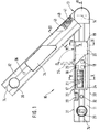
- FIG. 1 shows a view of the angle measuring device according to the invention
- Figure 2 shows a section along line II-II in Figure 1
- Figure 3 is a perspective Representation of a rotor from Figure 2
- Figure 3a a Partial view of the rotor
- Figure 4 is a section along the line IV-IV in Figure 1
- Figure 5 shows a section along line V-V in Figure 1
- Figure 6 is a section along line VI-VI in Figure 1.
- 10 denotes an angle measuring device a first leg 11 and a second leg 12 having.
- the legs 11 and 12 are about a hinge 13 around a common pivot axis 14 relative to each other pivoted.
- the first leg 11 is a rectangular hollow profile 11a and the second leg 12 formed as a U-profile 12a.
- An open side of the U-profile 12a is the hollow profile 11a facing such that the hollow profile 12a from the U-profile 12a in a folding position of the angle measuring device 10 in itself is recorded.
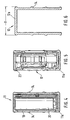
- a display device 17 for displaying angle values as well as function keys 18 for entering commands housed.
- a battery housing 19 for receiving indicated batteries or battery cells 20 and one with the Display device 17 coupled evaluation device 21.
- Die Components 17 to 21 form an assembly unit 23 assembled and into one towards the second leg 12 open U-shaped recess in the first leg 11 used.
- the battery housing 19 is by means of a cover 25 closable, the articulated in a housing 26 of the Mounting unit 23 is mounted and to close the Battery housing 19 latched to the housing 26.
- Spirit levels are also located in the first leg 11 28, 29 for vertical and horizontal alignment of the first leg 11.
- the dragonflies 28, 29 are matched on a first contact surface 30 on the first leg 11, the is parallel to an inner bearing surface 31.
- a Through hole 32 extends through the first leg 11 in Transverse direction parallel to the pivot axis 14.
- the U-shaped second leg 12 points in its two parallel side faces different window-shaped Openings on.
- a first viewing window 34 is permitted the reading of the display device 17 and the operation of the Function keys 18 in the folded position.
- a second Viewing window 35 allows the view of the in this position Dragonfly 29.
- a window 36 is aligned in the retracted position with the through hole 32 so that the angle measuring device 10 in the folded position e.g. to be hung on a wall hook can.
- the joint 13 is shown in more detail in FIG.
- a base body 40 On the U profile of the second leg 12 is a base body 40 through Screws 41 ( Figure 1) attached.
- the base body 40 forms in the region of the joint 13 a cylindrical receptacle 42, in a bearing part 43 is inserted centrally and by means of Fixing screws 44 is fixed.
- the bearing part 43 is shaped like a hollow cylinder. That forms inside Bearing part 43 has a pot bottom 57. With its outer circumference 45 the bearing part 43 forms a bearing seat 46.
- the bearing holder 46 is concentric with the pivot axis 14 and supports a swivel arm 47 on a sliding bush 48 Bearing part 43.
- the swivel arm 47 is with the first leg 11 rotatably connected.
- the sliding bush 48 is over one Sliding ring 49 and a snap ring 50 on the bearing part 43 axially secured.
- a spring washer or not shown Disc spring between snap ring 50 and sliding beech 48 ensures for the compensation of the axial play and for the desired one Resistance to rotation between the legs 11, 12.
- the bearing part 43 takes one in its central cavity 51 electric drive motor 52.
- the drive motor 52 has a drive shaft 53 which is concentric with the pivot axis 14 lies.
- the drive shaft 53 is made of a cylindrical Bearing projection 55 emerges from the housing of the drive motor 52 is formed and by engaging in a concentric Bore 56 in the bottom 57 of the bearing part 43 with the Pivot axis 14 is centered in alignment.
- Drive motor 52 and drive shaft 53 form drive means 54 for one Rotor 64.
- a swivel bracket 58 rotatably mounted with the first leg 11 is rotationally coupled.
- Another carrier 59 is over a Retaining screw 60 is firmly connected to the bearing part 43 and thus rotatably arranged on the second leg 12.
- Swivel bracket 58 and bracket 59 each carry a sensor 61, 62.
- sensors 61, 62 are switched on Photoelectric barriers formed, but others can non-contact sensors such as Hall sensors Find use.
- the rotor 64 is non-rotatably on the drive shaft 53 arranged.
- the rotor 64 is a circular disk formed on the radially outside a nose 65 is formed.
- the rotor 64 is for attachment to the drive shaft 53 provided with a hub 66.
- the disc-shaped part is between Nose 65 and pivot axis 14 have a compensating bore 68 provided, by means of a conditional on the nose 65 Unbalance is compensated.
- the nose 65 is shown, the outer circumference of the red 64 is arranged.
- the nose 65 has one Breaker edge 65a, which is at least in the area of Coverage with the sensors 61, 62 along one through the Extending pivot axis 14 going radial beam 14a. On in this way the interruption is independent of tolerances with regard to the distance from pivot axis 14 and nose 65.
- the joint 13 is on the part of the first leg 11 of a first cover 70 and on the part of the second leg 12 covered by a lid 71.
- the drive motor 52 is via connecting lines, not shown, with the Batteries 20 connected.
- the joint 13 is so compact trained that it is within a width B of the second Leg 12 lies, which is very good Apply properties for the angle measuring device 10.
- leg 11 is in each case shown in section, with a battery 20 in FIG is recognizable in the battery housing 19 and in FIG Display device 17 shown in the assembly unit 23 is.
- FIG. 6 this is the first leg 11 U-profile of the second leg 12 shown.
- the function of the angle measuring device is as follows: For The rotor 64 is measured by the drive means 54 spun. The sensors 61, 62 periodically from the breaker edge 65a of the nose 65 run through. The sensors 61, 62 generate during the passage of the Nose 65 each signal level changes in the Evaluation device 21 preferably by means of electronic Counters are recorded and converted into angle values. Through the Recording the transit time between passing the sensors 61, 62 and the recording of the orbital period until the next Passing of the respective sensor 61, 62 is possible Form an angular ratio that is independent of Speed fluctuations between different runs is. The corresponding angular ratio is constant Angle size, e.g. 360 °, multiplied and in the Display device 17 issued.
Landscapes
- Physics & Mathematics (AREA)
- General Physics & Mathematics (AREA)
- Length Measuring Devices With Unspecified Measuring Means (AREA)
- A Measuring Device Byusing Mechanical Method (AREA)
Applications Claiming Priority (2)
| Application Number | Priority Date | Filing Date | Title |
|---|---|---|---|
| DE19743568A DE19743568A1 (de) | 1997-10-02 | 1997-10-02 | Winkelmeßgerät |
| DE19743568 | 1997-10-02 |
Publications (3)
| Publication Number | Publication Date |
|---|---|
| EP0907066A2 true EP0907066A2 (fr) | 1999-04-07 |
| EP0907066A3 EP0907066A3 (fr) | 2000-10-18 |
| EP0907066B1 EP0907066B1 (fr) | 2006-01-04 |
Family
ID=7844388
Family Applications (1)
| Application Number | Title | Priority Date | Filing Date |
|---|---|---|---|
| EP98116516A Expired - Lifetime EP0907066B1 (fr) | 1997-10-02 | 1998-09-01 | Dispositif de mesure d'angles |
Country Status (3)
| Country | Link |
|---|---|
| US (1) | US6104480A (fr) |
| EP (1) | EP0907066B1 (fr) |
| DE (2) | DE19743568A1 (fr) |
Cited By (2)
| Publication number | Priority date | Publication date | Assignee | Title |
|---|---|---|---|---|
| AT511462A4 (de) * | 2011-06-24 | 2012-12-15 | Trumpf Maschinen Austria Gmbh | Messvorrichtung für biegewerkstücke |
| US11497592B2 (en) * | 2017-04-28 | 2022-11-15 | Universidad De La Frontera | Instrument for in situ measurement of the angle of convergence in a dental preparation |
Families Citing this family (18)
| Publication number | Priority date | Publication date | Assignee | Title |
|---|---|---|---|---|
| US6240649B1 (en) * | 1999-06-10 | 2001-06-05 | Mcelroy Paul T. | Sighting assembly |
| US20040215387A1 (en) | 2002-02-14 | 2004-10-28 | Matsushita Electric Industrial Co., Ltd. | Method for transmitting location information on a digital map, apparatus for implementing the method, and traffic information provision/reception system |
| JP3481168B2 (ja) | 1999-08-27 | 2003-12-22 | 松下電器産業株式会社 | デジタル地図の位置情報伝達方法 |
| JP5041638B2 (ja) | 2000-12-08 | 2012-10-03 | パナソニック株式会社 | デジタル地図の位置情報伝達方法とそれに使用する装置 |
| AU1501001A (en) * | 2001-01-16 | 2002-07-18 | Montenegro, Maria | An apparatus for measuring angles |
| JP4663136B2 (ja) | 2001-01-29 | 2011-03-30 | パナソニック株式会社 | デジタル地図の位置情報伝達方法と装置 |
| JP4749594B2 (ja) * | 2001-04-27 | 2011-08-17 | パナソニック株式会社 | デジタル地図の位置情報伝達方法 |
| JP4230132B2 (ja) | 2001-05-01 | 2009-02-25 | パナソニック株式会社 | デジタル地図の形状ベクトルの符号化方法と位置情報伝達方法とそれを実施する装置 |
| USD493734S1 (en) | 2002-12-03 | 2004-08-03 | Merle R. Ellis | Angle measuring device |
| DE102005059538B4 (de) * | 2005-12-13 | 2018-08-23 | Asm Automation Sensorik Messtechnik Gmbh | Scharnier-Sensor |
| US7472489B2 (en) * | 2006-03-10 | 2009-01-06 | Curtis Douglas Frank | Rowing device, digital pitch meter and other devices |
| US20070283587A1 (en) * | 2006-06-08 | 2007-12-13 | John Cerwin | Angle measuring device |
| US7726034B2 (en) * | 2007-03-09 | 2010-06-01 | Barry Douglas Wixey | Digital protractor |
| DE102008008846A1 (de) | 2008-02-13 | 2009-09-17 | Robert Bosch Gmbh | Messwerkzeug |
| CN201247026Y (zh) * | 2008-08-22 | 2009-05-27 | 桂林市晶瑞传感技术有限公司 | 多功能数显角度尺 |
| TWM378845U (en) * | 2009-12-14 | 2010-04-21 | Jin-Yi Gao | Projection type angle square |
| US10377611B2 (en) | 2016-10-28 | 2019-08-13 | Advance Lifts, Inc. | Scissors lift with height sensor system |
| USD995325S1 (en) * | 2022-01-20 | 2023-08-15 | Jeremy Cooper | Level and angle finder tool |
Family Cites Families (8)
| Publication number | Priority date | Publication date | Assignee | Title |
|---|---|---|---|---|
| US4513512A (en) * | 1982-07-02 | 1985-04-30 | Nestle & Fischer | Angle-measuring instrument having an indicator for the degree of angle |
| JPS608811U (ja) * | 1983-06-29 | 1985-01-22 | 旭光学工業株式会社 | 角度測定装置 |
| FR2558950B1 (fr) * | 1984-02-01 | 1986-06-27 | Rech Const Electroniqu Et | Codeur angulaire pour le codage d'angle zenithal entre une direction determinee variable et la verticale, en particulier pour theodolite |
| IL75319A0 (en) * | 1985-05-28 | 1985-09-29 | Robomatix Ltd | Angle encoder |
| DE8902987U1 (de) * | 1989-03-10 | 1989-04-20 | Gottlieb Nestle GmbH & Co KG, 7295 Dornstetten | Winkelmesser |
| DE4237076A1 (en) * | 1992-11-03 | 1993-04-15 | Ulrich Rapp | Angle measuring using rotor - rotating rotor at known angular speed exchanging directionally dependent signals with measurement and reference points |
| DE4240625A1 (de) * | 1992-12-03 | 1994-06-09 | Koerber Karlheinz | Dentaler Winkelsteller |
| DE29703041U1 (de) * | 1997-02-20 | 1997-04-17 | Erhartitsch, Karl, 81379 München | Hochgenaues elektronisches Winkelmeßgerät |
-
1997
- 1997-10-02 DE DE19743568A patent/DE19743568A1/de not_active Withdrawn
-
1998
- 1998-08-17 US US09/135,337 patent/US6104480A/en not_active Expired - Lifetime
- 1998-09-01 DE DE59813325T patent/DE59813325D1/de not_active Expired - Lifetime
- 1998-09-01 EP EP98116516A patent/EP0907066B1/fr not_active Expired - Lifetime
Cited By (2)
| Publication number | Priority date | Publication date | Assignee | Title |
|---|---|---|---|---|
| AT511462A4 (de) * | 2011-06-24 | 2012-12-15 | Trumpf Maschinen Austria Gmbh | Messvorrichtung für biegewerkstücke |
| US11497592B2 (en) * | 2017-04-28 | 2022-11-15 | Universidad De La Frontera | Instrument for in situ measurement of the angle of convergence in a dental preparation |
Also Published As
| Publication number | Publication date |
|---|---|
| DE59813325D1 (de) | 2006-03-30 |
| EP0907066A3 (fr) | 2000-10-18 |
| US6104480A (en) | 2000-08-15 |
| EP0907066B1 (fr) | 2006-01-04 |
| DE19743568A1 (de) | 1999-04-08 |
Similar Documents
| Publication | Publication Date | Title |
|---|---|---|
| EP0907066A2 (fr) | Dispositif de mesure d'angles | |
| AT508705B1 (de) | Rotationsviskosimeter | |
| DE4497719C2 (de) | Gerätehalterung mit mindestens einer Schwenkachse mit Dämpfung | |
| DE3103467A1 (de) | Kurskreisel | |
| AT521097B1 (de) | Rotationsviskosimeter zur Messung der Viskosität von Stoffen | |
| DE3836935C2 (fr) | ||
| DE60133506T2 (de) | Drehwinkelgeber | |
| EP0334929B1 (fr) | Goniometre avec capteur electronique de mesure et affichage numerique | |
| DE19637967A1 (de) | Winkelsensor | |
| DE68903942T2 (de) | Drehbarer potentiometrischer umsetzer. | |
| DE19708323B4 (de) | Anordnung zum Messen der axialen Bewegung bei einer luftgelagerten Spindel | |
| DE8902987U1 (de) | Winkelmesser | |
| DE3736546C2 (fr) | ||
| DE9308687U1 (de) | Winkelmesser mit Zifferblatt-Ablesung | |
| DE4411335C1 (de) | Selbstkalibrierende Neigungsmeßvorrichtung | |
| DE10062296C2 (de) | Neigungsgeber | |
| DE202005019830U1 (de) | Drehgeber | |
| DE2511985C2 (de) | Vorrichtung zum Messen der Viskosität | |
| DD265681A1 (de) | Horizontiergeber | |
| DE4014007A1 (de) | Halterung eines fliegend auf einer rotierenden welle gelagerten gehaeuses eines drehzahlgebers | |
| DE3218451C2 (fr) | ||
| DE3520453C1 (de) | Meßvorrichtung für Videoköpfe | |
| DE2745852A1 (de) | Drehantenne | |
| DE102005004181B4 (de) | Lenkvorrichtung für ein Flurförderzeug | |
| CN112923872A (zh) | 一种通用角度检测装置及车辆 |
Legal Events
| Date | Code | Title | Description |
|---|---|---|---|
| PUAI | Public reference made under article 153(3) epc to a published international application that has entered the european phase |
Free format text: ORIGINAL CODE: 0009012 |
|
| AK | Designated contracting states |
Kind code of ref document: A2 Designated state(s): CH DE FR GB IT LI |
|
| AX | Request for extension of the european patent |
Free format text: AL;LT;LV;MK;RO;SI |
|
| PUAL | Search report despatched |
Free format text: ORIGINAL CODE: 0009013 |
|
| AK | Designated contracting states |
Kind code of ref document: A3 Designated state(s): AT BE CH CY DE DK ES FI FR GB GR IE IT LI LU MC NL PT SE |
|
| AX | Request for extension of the european patent |
Free format text: AL;LT;LV;MK;RO;SI |
|
| 17P | Request for examination filed |
Effective date: 20010418 |
|
| AKX | Designation fees paid |
Free format text: CH DE FR GB IT LI |
|
| GRAP | Despatch of communication of intention to grant a patent |
Free format text: ORIGINAL CODE: EPIDOSNIGR1 |
|
| GRAS | Grant fee paid |
Free format text: ORIGINAL CODE: EPIDOSNIGR3 |
|
| GRAA | (expected) grant |
Free format text: ORIGINAL CODE: 0009210 |
|
| AK | Designated contracting states |
Kind code of ref document: B1 Designated state(s): CH DE FR GB IT LI |
|
| REG | Reference to a national code |
Ref country code: GB Ref legal event code: FG4D Free format text: NOT ENGLISH |
|
| REG | Reference to a national code |
Ref country code: CH Ref legal event code: NV Representative=s name: SCINTILLA AG, DIREKTION Ref country code: CH Ref legal event code: EP |
|
| REF | Corresponds to: |
Ref document number: 59813325 Country of ref document: DE Date of ref document: 20060330 Kind code of ref document: P |
|
| GBT | Gb: translation of ep patent filed (gb section 77(6)(a)/1977) |
Effective date: 20060410 |
|
| ET | Fr: translation filed | ||
| PG25 | Lapsed in a contracting state [announced via postgrant information from national office to epo] |
Ref country code: LI Free format text: LAPSE BECAUSE OF NON-PAYMENT OF DUE FEES Effective date: 20060930 Ref country code: CH Free format text: LAPSE BECAUSE OF NON-PAYMENT OF DUE FEES Effective date: 20060930 |
|
| PLBE | No opposition filed within time limit |
Free format text: ORIGINAL CODE: 0009261 |
|
| STAA | Information on the status of an ep patent application or granted ep patent |
Free format text: STATUS: NO OPPOSITION FILED WITHIN TIME LIMIT |
|
| 26N | No opposition filed |
Effective date: 20061005 |
|
| REG | Reference to a national code |
Ref country code: CH Ref legal event code: PL |
|
| PGFP | Annual fee paid to national office [announced via postgrant information from national office to epo] |
Ref country code: IT Payment date: 20090924 Year of fee payment: 12 |
|
| PG25 | Lapsed in a contracting state [announced via postgrant information from national office to epo] |
Ref country code: IT Free format text: LAPSE BECAUSE OF NON-PAYMENT OF DUE FEES Effective date: 20100901 |
|
| PGFP | Annual fee paid to national office [announced via postgrant information from national office to epo] |
Ref country code: GB Payment date: 20130920 Year of fee payment: 16 |
|
| GBPC | Gb: european patent ceased through non-payment of renewal fee |
Effective date: 20140901 |
|
| PG25 | Lapsed in a contracting state [announced via postgrant information from national office to epo] |
Ref country code: GB Free format text: LAPSE BECAUSE OF NON-PAYMENT OF DUE FEES Effective date: 20140901 |
|
| REG | Reference to a national code |
Ref country code: FR Ref legal event code: PLFP Year of fee payment: 19 |
|
| REG | Reference to a national code |
Ref country code: FR Ref legal event code: PLFP Year of fee payment: 20 |
|
| PGFP | Annual fee paid to national office [announced via postgrant information from national office to epo] |
Ref country code: FR Payment date: 20170925 Year of fee payment: 20 |
|
| PGFP | Annual fee paid to national office [announced via postgrant information from national office to epo] |
Ref country code: DE Payment date: 20171128 Year of fee payment: 20 |
|
| REG | Reference to a national code |
Ref country code: DE Ref legal event code: R071 Ref document number: 59813325 Country of ref document: DE |