EP0907066B1 - Winkelmessgerät - Google Patents
Winkelmessgerät Download PDFInfo
- Publication number
- EP0907066B1 EP0907066B1 EP98116516A EP98116516A EP0907066B1 EP 0907066 B1 EP0907066 B1 EP 0907066B1 EP 98116516 A EP98116516 A EP 98116516A EP 98116516 A EP98116516 A EP 98116516A EP 0907066 B1 EP0907066 B1 EP 0907066B1
- Authority
- EP
- European Patent Office
- Prior art keywords
- measuring device
- angle measuring
- limb
- limbs
- rotor
- Prior art date
- Legal status (The legal status is an assumption and is not a legal conclusion. Google has not performed a legal analysis and makes no representation as to the accuracy of the status listed.)
- Expired - Lifetime
Links
- 238000011156 evaluation Methods 0.000 claims description 3
- 230000004888 barrier function Effects 0.000 claims description 2
- 238000005259 measurement Methods 0.000 description 4
- 241000238633 Odonata Species 0.000 description 3
- 238000004519 manufacturing process Methods 0.000 description 2
- 230000004308 accommodation Effects 0.000 description 1
- 230000015572 biosynthetic process Effects 0.000 description 1
- 230000001419 dependent effect Effects 0.000 description 1
- 238000001514 detection method Methods 0.000 description 1
- 230000002035 prolonged effect Effects 0.000 description 1
Images


Classifications
-
- G—PHYSICS
- G01—MEASURING; TESTING
- G01B—MEASURING LENGTH, THICKNESS OR SIMILAR LINEAR DIMENSIONS; MEASURING ANGLES; MEASURING AREAS; MEASURING IRREGULARITIES OF SURFACES OR CONTOURS
- G01B5/00—Measuring arrangements characterised by the use of mechanical techniques
- G01B5/24—Measuring arrangements characterised by the use of mechanical techniques for measuring angles or tapers; for testing the alignment of axes
Definitions
- the invention relates to an angle measuring device according to the preamble of claim 1. It is already an angle measuring device known (DE-U-89 02 987.9) having two pivotable about a common pivot axis relative to each other leg, which are coupled together via a potentiometer, which allows the measurement of the included angle between the legs.
- the potentiometric measurement of the angle is subject to errors that are above a desired angular resolution in the 0.1 ° range.
- an angle measuring device (DE 297 03 041 U1), which is equipped with two rotationally coupled, to be driven rotating disks, which cooperate with each schenkelfesten sensors.
- Drive shaft and sensors are mounted at different angles in this angle, which brings an increased measurement inaccuracy with it.
- the provision of two discs with associated Sensor technology is also expensive and therefore expensive to manufacture.
- the large space required in the known angle measuring makes the placement of the drive of the discs within a pivot joint of the legs impossible. As a result, the removal of an angle set between the legs or the application of the legs to an angle to be determined is made more difficult.
- the mutual storage of the legs via three arranged in a plane bearings, the production-related ensure sufficient concentricity of the legs.
- the angle measuring device with the features of claim 1 has the advantage of enabling a cost-effective angle measurement with high accuracy.
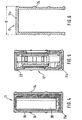
- FIG. 1 shows a view of the angle measuring device according to the invention
- Figure 2 is a section along line II-II in Figure 1
- Figure 3 is a perspective view of a rotor of Figure 2
- Figure 3a a Partial view of the rotor
- Figure 4 is a section along line IV-IV in Figure 1
- Figure 5 is a section along line VV in Figure 1
- Figure 6 is a section along line VI-VI in Figure 1 ..
- 10 denotes an angle measuring device which has a first leg 11 and a second leg 12.
- the legs 11 and 12 are pivotally mounted about a joint 13 about a common pivot axis 14 relative to each other.
- the first leg 11 is formed as a rectangular hollow profile 11a and the second leg 12 as a U-profile 12a.
- An open side of the U-profile 12a is facing the hollow profile 11a such that the hollow profile 12a is received by the U-profile 12a in a Einklapp ein of the Winkelmeß réelles 10 in itself.
- a display device 17 for displaying angle values and function keys 18 for the input of commands is housed.
- a battery housing 19 for receiving dashed lines indicated batteries or battery cells 20 and coupled to the display device 17 evaluation 21.
- the components 17 to 21 are assembled into a mounting unit 23 and in a second leg 12 out U-shaped recess in the first leg 11 is inserted.
- the battery housing 19 is closed by means of a lid 25 which is articulated in a housing 26 of the mounting unit 23 and locked to close the battery case 19 to the housing 26.
- first leg 11 In the first leg 11 are also spirit level dragonflies 28, 29 for vertical and horizontal alignment of the first leg 11.
- the dragonflies 28, 29 are matched to a first bearing surface 30 on the first leg 11, which is parallel to an inner bearing surface 31.
- a through hole 32 extends through the first leg 11 in the transverse direction parallel to the pivot axis 14.
- the U-shaped second leg 12 has in its two parallel side surfaces on various window-shaped viewing recesses.
- a first viewing window 34 allows the reading of the display device 17 and the operation of the function keys 18 in the Einklapp ein.
- a second viewing window 35 allows in this position the view of the dragonfly 29.
- a window 36 is aligned in the Einklapp ein with the through hole 32, so that the angle measuring device 10 in the Einklapp ein z. can be hung on a wall hook.
- the joint 13 is shown in more detail.
- a base body 40 by screws 41 (Figure 1) is attached.
- the base body 40 forms in the region of the joint 13 a cylindrical receptacle 42, in which a bearing part 43 is inserted centrally and fixed by means of fastening screws 44.
- the bearing part 43 is hollow-cylindrical. Inwardly to the bearing part 43 forms a pot bottom 57. With its outer periphery 45, the bearing part 43 forms a bearing receptacle 46th
- the bearing receptacle 46 is concentric with the pivot axis 14 and supports a pivot arm 47 via a sliding bush 48 on the bearing part 43.
- the pivot arm 47 is rotatably connected to the first leg 11.
- the slide bush 48 is axially secured via a slide ring 49 and a snap ring 50 on the bearing part 43.
- a not shown spring washer or disc spring between snap ring 50 and slide bushing 48 provides for the compensation of the axial play and for the desired torsional resistance between the legs 11, 12th
- the bearing part 43 receives in its central cavity 51 an electric drive motor 52.
- the drive motor 52 has a drive shaft 53 which is concentric with the pivot axis 14.
- the drive shaft 53 protrudes from a cylindrical bearing projection 55 which is formed by the housing of the drive motor 52 and is aligned by engagement with a concentric bore 56 in the bottom 57 of the bearing part 43 with the pivot axis 14 in alignment.
- Drive motor 52 and drive shaft 53 form drive means 54 for a rotor 64.
- a pivot support 58 is rotatably mounted, which is rotationally coupled to the first leg 11.
- Another carrier 59 is fixedly connected via a retaining screw 60 with the bearing part 43 and thus rotatably disposed on the second leg 12.
- Swivel support 58 and support 59 each carry a sensor 61, 62.
- the sensors 61, 62 formed by light barriers, but it can also find other non-contact sensors such as Hall sensors use.
- the rotor 64 On the drive shaft 53, the rotor 64 is arranged rotationally fixed.
- the rotor 64 is formed as a circular disc, to the radially outside of a nose 65 is formed.
- the rotor 64 For attachment to the drive shaft 53, the rotor 64 is provided with a hub 66.
- the hub 66 is connected to the disk-shaped part of the rotor 64 via ribs 67.
- a compensating bore 68 In the disk-shaped part is provided between the nose 65 and the pivot axis 14 a compensating bore 68, by means of which a conditional by the nose 65 unbalance is compensated.
- the nose 65 is shown, which is arranged on the outer circumference of the Rotos 64.
- the nose 65 has an interrupting edge 65a, which extends at least in the region of the overlap with the sensors 61, 62 along a radial ray 14a passing through the pivot axis 14. In this way, the interruption is independent of tolerances with respect to the distance of pivot axis 14 and nose 65th
- the hinge 13 is covered by the first leg 11 by means of a first cover 70 and the side of the second leg 12 by a cover 71.
- the drive motor 52 is connected via not shown leads to the batteries 20.
- the joint 13 is formed so compact that it lies within a width B of the second leg 12, resulting in very good application properties for the angle measuring device 10.
- FIG. 6 shows the U-profile of the second leg 12 receiving the first leg 11.
- the function of the angle measuring device is as follows: For measuring the angle, the rotor 64 is rotated by the drive means 54. In this case, the sensors 61, 62 are traversed periodically by the interrupting edge 65a of the nose 65. The sensors 61, 62 generate during passage of the nose 65 each signal level changes, which are detected in the evaluation device 21, preferably by means of electronic counters and converted into angular values. By detecting the transit time between the passage of the sensors 61, 62 and the detection of the circulation time to the renewed Passing the respective sensor 61, 62 can form an angular ratio, which is independent of speed fluctuations between different passes. The corresponding angular ratio is multiplied by a constant angle size, eg 360 °, and output in the display device 17.
- a constant angle size eg 360 °
Landscapes
- Physics & Mathematics (AREA)
- General Physics & Mathematics (AREA)
- Length Measuring Devices With Unspecified Measuring Means (AREA)
- A Measuring Device Byusing Mechanical Method (AREA)
Description
- Die Erfindung geht aus von einem Winkelmeßgerät nach dem Oberbegriff des Anspruchs 1. Es ist schon ein Winkelmeßgerät bekannt (DE-U-89 02 987.9), das zwei um eine gemeinsame Schwenkachse relativ zueinander schwenkbare Schenkel aufweist, die über ein Potentiometer miteinander gekoppelt sind, das die Messung des zwischen den Schenkeln eingeschlossenen Winkels ermöglicht.
- Aufgrund der Berührung von Schleifer und Widerstandsbahn des Potentiometers kann sich nach längerem Gebrauch ein unerwünschter Verschleiß einstellen. Darüber hinaus ist die potentiometrische Messung des Winkels mit Fehlern behaftet, die über einer gewünschten Winkelauflösung im 0,1°-Bereich liegen.
- Weiterhin ist ein Winkelmeßgerät bekannt (DE 297 03 041 U1), das mit zwei drehschlüssig gekoppelten, drehend anzutreibenden Scheiben ausgestattet ist, die jeweils mit schenkelfesten Sensoren zusammenwirken. Antriebswelle und Sensoren sind bei diesem Winkelmeßgerät an unterschiedlichen Schenkeln gelagert, was eine erhöhte Meßungenauigkeit mit sich bringt. Das Vorsehen von zwei Scheiben mit zugehöriger Sensorik ist zudem aufwendig und daher teuer in der Herstellung. Der bei dem bekannten Winkelmeßgerät erforderliche große Bauraum macht die Unterbringung des Antriebes der Scheiben innerhalb eines Schwenkgelenks der Schenkel unmöglich. Dadurch wird das Abtragen eines zwischen den Schenkeln eingestellten Winkels bzw. das Anlegen der Schenkel an einen zu ermittelnden Winkel erschwert. Die gegenseitige Lagerung der Schenkel erfolgt über drei in einer Ebene angeordnete Wälzlager, die fertigungsbedingt keine ausreichende Konzentrizität der Schenkel gewährleisten.
- Das erfindungsgemäße Winkelmeßgerät mit den Merkmalen des Anspruchs 1 hat den Vorteil, eine kostengünstige Winkelmessung bei hoher Meßgenauigkeit zu ermöglichen.
- Durch die in den abhängigen Ansprüchen aufgeführten Maßnahmen sind vorteilhafte Weiterbildungen und Verbesserungen des erfindungsgemäßen Winkelmeßgeräts möglich. Besonders vorteilhaft ist die Ausbildung des Gelenks mit einem hohlzylindrischen Lagerteil, das die Antriebsmittel in sich aufnimmt. Auf diese Weise ist eine platzsparende Anordnung möglich, die die Unterbringung des Schwenkgelenks innerhalb des Schenkelprofils gestattet.
- Ein Ausführungsbeispiel der Erfindung ist in der Zeichnung dargestellt und in der nachfolgenden Beschreibung näher erläutert. Es zeigen Figur 1 eine Ansicht des erfindungsgemäßen Winkelmeßgeräts, Figur 2 einen Schnitt entlang Linie II-II in Figur 1, Figur 3 eine perspektivische Darstellung eines Rotors aus Figur 2, Figur 3a eine Teilansicht des Rotors, Figur 4 einen Schnitt gemäß Linie IV-IV in Figur 1, Figur 5 einen Schnitt gemäß Linie V-V in Figur 1 und Figur 6 einen Schnitt gemäß Linie VI-VI in Figur 1.
- In Figur 1 ist mit 10 ein Winkelmeßgerät bezeichnet, das einen ersten Schenkel 11 und einen zweiten Schenkel 12 aufweist. Die Schenkel 11 und 12 sind über ein Gelenk 13 um eine gemeinsame Schwenkachse 14 relativ zueinander schwenkbar gelagert.
- Der erste Schenkel 11 ist als rechteckförmiges Hohlprofil 11a und der zweite Schenkel 12 als U-Profil 12a ausgebildet. Eine offene Seite des U-Profils 12a ist dem Hohlprofil 11a derart zugewandt, daß das Hohlprofil 12a vom U-Profil 12a in einer Einklappstellung des Winkelmeßgeräts 10 in sich aufgenommen wird. Im Hohlprofil 11a des ersten Schenkels 11 ist eine Anzeigevorrichtung 17 zur Anzeige von Winkelwerten sowie Funktionstasten 18 für die Eingabe von Befehlen untergebracht. Darüber hinaus befindet sich im ersten Schenkel 11 ein Batteriegehäuse 19 zur Aufnahme gestrichelt angedeuteter Batterien bzw. Akkuzellen 20 und eine mit der Anzeigevorrichtung 17 gekoppelte Auswerteeinrichtung 21. Die Bauteile 17 bis 21 sind zu einer Montageeinheit 23 zusammengesetzt und in eine zum zweiten Schenkel 12 hin offene U-förmige Aussparung im ersten Schenkel 11 eingesetzt. Das Batteriegehäuse 19 ist mittels eines Deckels 25 verschließbar, der gelenkig in einem Gehäuse 26 der Montageeinheit 23 gelagert ist und zum Schließen des Batteriegehäuses 19 mit dem Gehäuse 26 verrastet.
- Im ersten Schenkel 11 befinden sich ferner Wasserwaagen-Libellen 28, 29 zur vertikalen und horizontalen Ausrichtung des ersten Schenkels 11. Die Libellen 28, 29 sind abgestimmt auf eine erste Auflagefläche 30 am ersten Schenkel 11, die parallel zu einer inneren Auflagefläche 31 liegt. Ein Durchgangsloch 32 durchragt den ersten Schenkel 11 in Querrichtung parallel zur Schwenkachse 14.
- Der U-förmige zweite Schenkel 12 weist in seinen beiden parallelen Seitenflächen verschiedene fensterförmige Sichtausnehmungen auf. Ein erstes Sichtfenster 34 gestattet das Ablesen der Anzeigevorrichtung 17 und die Bedienung der Funktionstasten 18 in der Einklappstellung. Ein zweites Sichtfenster 35 erlaubt in dieser Stellung den Blick auf die Libelle 29. Ein Fenster 36 fluchtet in der Einklappstellung mit dem Durchgangsloch 32, so daß das Winkelmeßgerät 10 in der Einklappstellung z.B. an einen Wandhaken gehängt werden kann.
- In Figur 2 ist das Gelenk 13 näher dargestellt. Am U-Profil des zweiten Schenkels 12 ist ein Grundkörper 40 durch Schrauben 41 (Figur 1) befestigt. Der Grundkörper 40 bildet im Bereich des Gelenks 13 eine zylindrische Aufnahme 42, in die ein Lagerteil 43 zentral eingesetzt ist und mittels Befestigungsschrauben 44 festgelegt ist. Das Lagerteil 43 ist hohlzylindrisch geformt. Nach innen zu bildet das Lagerteil 43 einen Topfboden 57. Mit seinem Außenumfang 45 bildet das Lagerteil 43 eine Lageraufnahme 46.
- Die Lageraufnahme 46 liegt konzentrisch zur Schwenkachse 14 und lagert einen Schwenkarm 47 über eine Gleitbuchse 48 am Lagerteil 43. Der Schwenkarm 47 ist mit dem ersten Schenkel 11 drehfest verbunden. Die Gleitbuchse 48 ist über einen Gleitring 49 und einen Sprengring 50 am Lagerteil 43 axial gesichert. Eine nicht näher dargestellte Federscheibe bzw. Tellerfeder zwischen Sprengring 50 und Gleitbuche 48 sorgt für den Ausgleich des Axialspieles und für den gewünschten Verdrehwiderstand zwischen den Schenkeln 11, 12.
- Das Lagerteil 43 nimmt in seinem zentralen Hohlraum 51 einen elektrischen Antriebsmotor 52 auf. Der Antriebsmotor 52 hat eine Antriebswelle 53, die konzentrisch zur Schwenkachse 14 liegt. Die Antriebswelle 53 steht aus einem zylindrischen Lagervorsprung 55 hervor, der vom Gehäuse des Antriebsmotors 52 gebildet wird und durch Eingriff in eine konzentrische Bohrung 56 im Boden 57 des Lagerteils 43 mit der Schwenkachse 14 fluchtend zentriert wird. Antriebsmotor 52 und Antriebswelle 53 bilden Antriebsmittel 54 für einen Rotor 64.
- Am Außenumfang 45 des Lagerteils 43 ist ein Schwenkträger 58 drehbar gelagert, der mit dem ersten Schenkel 11 drehgekoppelt ist. Ein weiterer Träger 59 ist über eine Halteschraube 60 mit dem Lagerteil 43 fest verbunden und somit drehfest am zweiten Schenkel 12 angeordnet. Schwenkträger 58 und Träger 59 tragen jeweils einen Sensor 61, 62. Im Beispielfall werden die Sensoren 61, 62 durch Lichtschranken gebildet, es können jedoch auch andere berührungslose Sensoren wie beispielsweise Hall-Geber Verwendung finden.
- Auf der Antriebswelle 53 ist der Rotor 64 drehfest angeordnet. Der Rotor 64 ist als kreisförmige Scheibe ausgebildet, an die radial außen eine Nase 65 angeformt ist. Zur Befestigung auf der Antriebswelle 53 ist der Rotor 64 mit einer Nabe 66 versehen. Aus Stabilitätsgründen ist die Nabe 66 mit dem scheibenförmigen Teil des Rotors 64 über Rippen 67 verbunden. Im scheibenförmigen Teil ist zwischen Nase 65 und Schwenkachse 14 eine Ausgleichsbohrung 68 vorgesehen, mittels der eine von der Nase 65 bedingte Unwucht ausgeglichen wird.
- In Figur 3a ist die Nase 65 dargestellt, die am Außenumfang des Rotos 64 angeordnet ist. Die Nase 65 weist eine Unterbrecherkante 65a auf, die sich zumindest im Bereich der Überdeckung mit den Sensoren 61, 62 entlang eines durch die Schwenkachse 14 gehenden Radialstrahls 14a erstreckt. Auf diese Weise ist die Unterbrechung unabhängig von Toleranzen hinsichtlich des Abstandes von Schwenkachse 14 und Nase 65.
- Das Gelenk 13 ist seitens des ersten Schenkels 11 mittels eines ersten Deckels 70 und seitens des zweiten Schenkels 12 durch einen Deckel 71 abgedeckt. Der Antriebsmotor 52 ist über nicht näher dargestellte Anschlußleitungen mit den Batterien 20 verbunden. Das Gelenk 13 ist derart kompakt ausgebildet, daß es innerhalb einer Breite B des zweiten Schenkels 12 liegt, wodurch sich sehr gute Anlegeeigenschaften für das Winkelmeßgerät 10 ergeben.
- In den Figuren 4 und 5 ist der Schenkel 11 jeweils geschnitten dargestellt, wobei in Figur 4 eine Batterie 20 im Batteriegehäuse 19 erkennbar ist und in Figur 5 die Anzeigevorrichtung 17 in der Montageeinheit 23 dargestellt ist. In Figur 6 ist das den ersten Schenkel 11 aufnehmende U-Profil des zweiten Schenkels 12 dargestellt.
- Die Funktion des Winkelmeßgerätes ist wie folgt: Zur Winkelmessung wird der Rotor 64 durch die Antriebsmittel 54 in Drehung versetzt. Dabei werden die Sensoren 61, 62 periodisch von der Unterbrecherkante 65a der Nase 65 durchlaufen. Die Sensoren 61, 62 erzeugen beim Durchlauf der Nase 65 jeweils Signalpegeländerungen, die in der Auswerteinrichtung 21 vorzugsweise mittels elektronischer Zähler erfaßt und in Winkelwerte umgesetzt werden. Durch die Erfassung der Laufzeit zwischen dem Passieren der Sensoren 61, 62 und die Erfassung der Umlaufzeit bis zum erneuten Passieren des jeweiligen Sensors 61, 62 läßt sich ein Winkelverhältnis bilden, das unabhängig von Drehzahlschwankungen zwischen verschiedenen Durchläufen ist. Das entsprechende Winkelverhältnis wird mit einer konstanten Winkelgröße, z.B. 360°, multipliziert und in der Anzeigevorrichtung 17 ausgegeben.
Claims (14)
- Winkelmeßgerät, mit wenigstens zwei Schenkeln (11, 12), die in einem Gelenk (13) um eine gemeinsame Schwenkachse (14) relativ zueinander schwenkbar gelagert sind, mit wenigstens einem Rotor (64), der über Antriebsmittel (54) um eine Drehachse drehend antreibbar ist, die mit der Schwenkachse (14) fluchtet, mit Referenzpunkten (61, 62), die den Schenkeln (11, 12) zugeordnet sind, und mit wenigstens einer Referenzmarke (65) an jedem Rotor (64), die mit diesem mitdreht und die Referenzpunkte (61, 62) auf einer umlaufenden Bahn passiert, dadurch gekennzeichnet, daß das Gelenk (13) ein zentrales Lagerteil (43) hat, das mit einem der Schenkel (12) fest verbunden ist und eine konzentrisch zur Schwenkachse (14) angeordnete Lageraufnahme (46) für den bzw. die anderen Schenkel (11) bildet.
- Winkelmeßgerät nach Anspruch 1, dadurch gekennzeichnet, daß das Lagerteil (43) hohlzylindrisch, vorzugsweise topfförmig, ausgebildet ist und zumindest zum Teil die Antriebsmittel (54) in sich aufnimmt, wobei die Lageraufnahme (46) für den anderen Schenkel (11) am Außenumfang des Lagerteils (43) vorgesehen ist.
- Winkelmeßgerät nach Anspruch 2, dadurch gekennzeichnet, daß die Antriebsmittel (54) einen Antriebsmotor (52) aufweisen, der mit einem Lagervorsprung (55) versehen ist, der konzentrisch zu einer Drehachse einer Antriebswelle (53) des Antriebsmotors (52) ausgerichtet ist und der in eine in einem Topfboden (57) des Lagerteils (43) befindliche Bohrung (56) greift, die konzentrisch zur Schwenkachse (14) liegt.
- Winkelmeßgerät nach einem der vorhergehenden Ansprüche, dadurch gekennzeichnet, daß ein erster Schenkel (11) aus einem viereckförmigen Hohlprofil (11a) und ein zweiter Schenkel (12) aus einem U-Profil (12a) besteht, wobei das U-Profil (12a) das Hohlprofil (11a) in einer Einklappstellung des Winkelmeßgeräts (10) in sich aufnimmt.
- Winkelmeßgerät nach Anspruch 4, dadurch gekennzeichnet, daß jeder Schenkel (11, 12) wenigstens ein Durchgangsloch (32, 36) aufweist, das in der Einklappstellung des Winkelmeßgeräts (10) mit dem entsprechenden Durchgangsloch des jeweils anderen Schenkels (12, 11) in Deckung kommt.
- Winkelmeßgerät nach einem der vorgehenden Ansprüche,
dadurch gekennzeichnet, daß die Referenzpunkte (61, 62) verschiedener Schenkel (11, 12) derart angeordnet sind, daß sie nacheinander von der Referenzmarke (65) desselben Rotors (64) durchlaufen werden. - Winkelmeßgerät nach einem der Ansprüche 1 bis 6, dadurch gekennzeichnet, daß als schenkelseitige Referenzpunkte (61, 62) Sensoren dienen.
- Winkelmeßgerät nach Anspruch 7, dadurch gekennzeichnet, daß die Sensoren (61, 62) durch Gabellichtschranken gebildet werden und die rotorseitige Referenzmarke durch eine über den Umfang des Rotors (34) hinausstehende Nase (65) gebildet wird.
- Winkelmeßgerät nach Anspruch 8, dadurch gekennzeichnet, daß die Nase (65) eine Unterbrecherkante aufweist, die zumindest teilweise entlang eines durch die Schwenkachse (14) gehenden Radialstrahls ausgebildet ist.
- Winkelmeßgerät nach Anspruch 9, dadurch gekennzeichnet, daß der Rotor (64) im wesentlichen als Scheibe ausgebildet ist, die zwecks Ausgleich von Unwucht eine Ausgleichsbohrung (68) radial zwischen Nase (65) und Schwenkachse (14) aufweist.
- Winkelmeßgerät nach Anspruch 7 oder 8, dadurch gekennzeichnet, daß das Lagerteil (43) einen Schwenkträger (58) konzentrisch zur Drehachse (14) lagert, der mit einem ersten Schenkel (11) drehschlüssig gekoppelt ist und der einen diesem Schenkel (11) zugeordneten Sensor (61) trägt.
- Winkelmeßgerät nach Anspruch 7, 8 oder 11, dadurch gekennzeichnet, daß am Lagerteil (43) ein Träger (59) drehfest gelagert ist, der einen dem zweiten Schenkel (12) zugeordneten Sensor (62) trägt.
- Winkelmeßgerät nach einem der vorhergehenden Ansprüche, dadurch gekennzeichnet, daß die Schenkel (11, 12) seitliche Meßflächen (11b, 12b) aufweisen und demgegenüber um 90° versetzte Auflageflächen (11c, 12c) haben, die nach außen vorstehende Rippen (74) aufweisen.
- Winkelmeßgerät nach einem der vorhergehenden Ansprüche, dadurch gekennzeichnet, daß in einem der Schenkel (11, 12) eine Auswerteeinrichtung (21) zusammen mit einer Anzeigevorrichtung (17) und Funktionstasten (18) untergebracht sind, die zu einer Montageeinheit (23) zusammengefaßt in den jeweiligen Schenkel (11, 12) eingesetzt sind.
Applications Claiming Priority (2)
| Application Number | Priority Date | Filing Date | Title |
|---|---|---|---|
| DE19743568 | 1997-10-02 | ||
| DE19743568A DE19743568A1 (de) | 1997-10-02 | 1997-10-02 | Winkelmeßgerät |
Publications (3)
| Publication Number | Publication Date |
|---|---|
| EP0907066A2 EP0907066A2 (de) | 1999-04-07 |
| EP0907066A3 EP0907066A3 (de) | 2000-10-18 |
| EP0907066B1 true EP0907066B1 (de) | 2006-01-04 |
Family
ID=7844388
Family Applications (1)
| Application Number | Title | Priority Date | Filing Date |
|---|---|---|---|
| EP98116516A Expired - Lifetime EP0907066B1 (de) | 1997-10-02 | 1998-09-01 | Winkelmessgerät |
Country Status (3)
| Country | Link |
|---|---|
| US (1) | US6104480A (de) |
| EP (1) | EP0907066B1 (de) |
| DE (2) | DE19743568A1 (de) |
Families Citing this family (20)
| Publication number | Priority date | Publication date | Assignee | Title |
|---|---|---|---|---|
| US6240649B1 (en) * | 1999-06-10 | 2001-06-05 | Mcelroy Paul T. | Sighting assembly |
| US20040215387A1 (en) | 2002-02-14 | 2004-10-28 | Matsushita Electric Industrial Co., Ltd. | Method for transmitting location information on a digital map, apparatus for implementing the method, and traffic information provision/reception system |
| JP3481168B2 (ja) | 1999-08-27 | 2003-12-22 | 松下電器産業株式会社 | デジタル地図の位置情報伝達方法 |
| JP5041638B2 (ja) | 2000-12-08 | 2012-10-03 | パナソニック株式会社 | デジタル地図の位置情報伝達方法とそれに使用する装置 |
| AU1501001A (en) * | 2001-01-16 | 2002-07-18 | Montenegro, Maria | An apparatus for measuring angles |
| JP4663136B2 (ja) | 2001-01-29 | 2011-03-30 | パナソニック株式会社 | デジタル地図の位置情報伝達方法と装置 |
| JP4749594B2 (ja) * | 2001-04-27 | 2011-08-17 | パナソニック株式会社 | デジタル地図の位置情報伝達方法 |
| JP4230132B2 (ja) | 2001-05-01 | 2009-02-25 | パナソニック株式会社 | デジタル地図の形状ベクトルの符号化方法と位置情報伝達方法とそれを実施する装置 |
| USD493734S1 (en) | 2002-12-03 | 2004-08-03 | Merle R. Ellis | Angle measuring device |
| DE102005059538B4 (de) * | 2005-12-13 | 2018-08-23 | Asm Automation Sensorik Messtechnik Gmbh | Scharnier-Sensor |
| US7472489B2 (en) * | 2006-03-10 | 2009-01-06 | Curtis Douglas Frank | Rowing device, digital pitch meter and other devices |
| US20070283587A1 (en) * | 2006-06-08 | 2007-12-13 | John Cerwin | Angle measuring device |
| US7726034B2 (en) * | 2007-03-09 | 2010-06-01 | Barry Douglas Wixey | Digital protractor |
| DE102008008846A1 (de) | 2008-02-13 | 2009-09-17 | Robert Bosch Gmbh | Messwerkzeug |
| CN201247026Y (zh) * | 2008-08-22 | 2009-05-27 | 桂林市晶瑞传感技术有限公司 | 多功能数显角度尺 |
| TWM378845U (en) * | 2009-12-14 | 2010-04-21 | Jin-Yi Gao | Projection type angle square |
| AT511462B1 (de) * | 2011-06-24 | 2012-12-15 | Trumpf Maschinen Austria Gmbh | Messvorrichtung für biegewerkstücke |
| US10377611B2 (en) * | 2016-10-28 | 2019-08-13 | Advance Lifts, Inc. | Scissors lift with height sensor system |
| US11497592B2 (en) * | 2017-04-28 | 2022-11-15 | Universidad De La Frontera | Instrument for in situ measurement of the angle of convergence in a dental preparation |
| USD995325S1 (en) * | 2022-01-20 | 2023-08-15 | Jeremy Cooper | Level and angle finder tool |
Family Cites Families (8)
| Publication number | Priority date | Publication date | Assignee | Title |
|---|---|---|---|---|
| US4513512A (en) * | 1982-07-02 | 1985-04-30 | Nestle & Fischer | Angle-measuring instrument having an indicator for the degree of angle |
| JPS608811U (ja) * | 1983-06-29 | 1985-01-22 | 旭光学工業株式会社 | 角度測定装置 |
| FR2558950B1 (fr) * | 1984-02-01 | 1986-06-27 | Rech Const Electroniqu Et | Codeur angulaire pour le codage d'angle zenithal entre une direction determinee variable et la verticale, en particulier pour theodolite |
| IL75319A0 (en) * | 1985-05-28 | 1985-09-29 | Robomatix Ltd | Angle encoder |
| DE8902987U1 (de) * | 1989-03-10 | 1989-04-20 | Gottlieb Nestle GmbH & Co KG, 7295 Dornstetten | Winkelmesser |
| DE4237076A1 (en) * | 1992-11-03 | 1993-04-15 | Ulrich Rapp | Angle measuring using rotor - rotating rotor at known angular speed exchanging directionally dependent signals with measurement and reference points |
| DE4240625A1 (de) * | 1992-12-03 | 1994-06-09 | Koerber Karlheinz | Dentaler Winkelsteller |
| DE29703041U1 (de) * | 1997-02-20 | 1997-04-17 | Erhartitsch, Karl, 81379 München | Hochgenaues elektronisches Winkelmeßgerät |
-
1997
- 1997-10-02 DE DE19743568A patent/DE19743568A1/de not_active Withdrawn
-
1998
- 1998-08-17 US US09/135,337 patent/US6104480A/en not_active Expired - Lifetime
- 1998-09-01 EP EP98116516A patent/EP0907066B1/de not_active Expired - Lifetime
- 1998-09-01 DE DE59813325T patent/DE59813325D1/de not_active Expired - Lifetime
Also Published As
| Publication number | Publication date |
|---|---|
| DE59813325D1 (de) | 2006-03-30 |
| EP0907066A3 (de) | 2000-10-18 |
| EP0907066A2 (de) | 1999-04-07 |
| DE19743568A1 (de) | 1999-04-08 |
| US6104480A (en) | 2000-08-15 |
Similar Documents
| Publication | Publication Date | Title |
|---|---|---|
| EP0907066B1 (de) | Winkelmessgerät | |
| AT508705B1 (de) | Rotationsviskosimeter | |
| DD297592A5 (de) | Werkzeugkopf fuer den einsatz in werkzeugmaschinen | |
| DE112010000835T5 (de) | Drehlagesensor | |
| WO1982002766A1 (en) | Gyroscopic compass | |
| EP0950876B1 (de) | Kapazitiver Winkelsensor | |
| AT521097B1 (de) | Rotationsviskosimeter zur Messung der Viskosität von Stoffen | |
| DE10052148B4 (de) | Vermessungsinstrument mit einem magnetischen Inkremental-Drehcodierer | |
| DE29602453U1 (de) | Inertialsensor-Anordnung | |
| EP0334929B1 (de) | Winkelmass mit elektronischem messwertgeber und digitaler anzeige | |
| DE68903942T2 (de) | Drehbarer potentiometrischer umsetzer. | |
| DE10039217A1 (de) | Vorrichtung und Verfahren zur berührungslosen Erfassung eines Drehwinkels bzw. einer Torsionsverdrehung | |
| DE2638248A1 (de) | Magnetischer schichtdickenmesser | |
| EP1688708A2 (de) | Vorrichtung zur Bestimmung eines absoluten Drehwinkels | |
| DE102008017917A1 (de) | Verfahren und Vorrichtung zur Revolverpositionierung | |
| DE4411335C1 (de) | Selbstkalibrierende Neigungsmeßvorrichtung | |
| DE19710217C1 (de) | Verfahren und Vorrichtung zur Seismometerprüfung | |
| EP1533212A1 (de) | Lenkwinkelsensor | |
| DE202005019830U1 (de) | Drehgeber | |
| DE2558026C3 (de) | Radauswuchtmaschine | |
| EP0362426A1 (de) | Strömungsmessvorrichtung | |
| WO2009127237A1 (de) | Sensoranordnung zur erfassung des drehwinkels einer um eine rotationsachse rotierenden anordnung | |
| DE1765664A1 (de) | Drehscheiben-Einstellaggregat | |
| WO2007093569A1 (de) | Messeinrichtung zur bestimmung eines drehwinkels | |
| WO2022144224A1 (de) | Elektromotor mit positionserfassung |
Legal Events
| Date | Code | Title | Description |
|---|---|---|---|
| PUAI | Public reference made under article 153(3) epc to a published international application that has entered the european phase |
Free format text: ORIGINAL CODE: 0009012 |
|
| AK | Designated contracting states |
Kind code of ref document: A2 Designated state(s): CH DE FR GB IT LI |
|
| AX | Request for extension of the european patent |
Free format text: AL;LT;LV;MK;RO;SI |
|
| PUAL | Search report despatched |
Free format text: ORIGINAL CODE: 0009013 |
|
| AK | Designated contracting states |
Kind code of ref document: A3 Designated state(s): AT BE CH CY DE DK ES FI FR GB GR IE IT LI LU MC NL PT SE |
|
| AX | Request for extension of the european patent |
Free format text: AL;LT;LV;MK;RO;SI |
|
| 17P | Request for examination filed |
Effective date: 20010418 |
|
| AKX | Designation fees paid |
Free format text: CH DE FR GB IT LI |
|
| GRAP | Despatch of communication of intention to grant a patent |
Free format text: ORIGINAL CODE: EPIDOSNIGR1 |
|
| GRAS | Grant fee paid |
Free format text: ORIGINAL CODE: EPIDOSNIGR3 |
|
| GRAA | (expected) grant |
Free format text: ORIGINAL CODE: 0009210 |
|
| AK | Designated contracting states |
Kind code of ref document: B1 Designated state(s): CH DE FR GB IT LI |
|
| REG | Reference to a national code |
Ref country code: GB Ref legal event code: FG4D Free format text: NOT ENGLISH |
|
| REG | Reference to a national code |
Ref country code: CH Ref legal event code: NV Representative=s name: SCINTILLA AG, DIREKTION Ref country code: CH Ref legal event code: EP |
|
| REF | Corresponds to: |
Ref document number: 59813325 Country of ref document: DE Date of ref document: 20060330 Kind code of ref document: P |
|
| GBT | Gb: translation of ep patent filed (gb section 77(6)(a)/1977) |
Effective date: 20060410 |
|
| ET | Fr: translation filed | ||
| PG25 | Lapsed in a contracting state [announced via postgrant information from national office to epo] |
Ref country code: LI Free format text: LAPSE BECAUSE OF NON-PAYMENT OF DUE FEES Effective date: 20060930 Ref country code: CH Free format text: LAPSE BECAUSE OF NON-PAYMENT OF DUE FEES Effective date: 20060930 |
|
| PLBE | No opposition filed within time limit |
Free format text: ORIGINAL CODE: 0009261 |
|
| STAA | Information on the status of an ep patent application or granted ep patent |
Free format text: STATUS: NO OPPOSITION FILED WITHIN TIME LIMIT |
|
| 26N | No opposition filed |
Effective date: 20061005 |
|
| REG | Reference to a national code |
Ref country code: CH Ref legal event code: PL |
|
| PGFP | Annual fee paid to national office [announced via postgrant information from national office to epo] |
Ref country code: IT Payment date: 20090924 Year of fee payment: 12 |
|
| PG25 | Lapsed in a contracting state [announced via postgrant information from national office to epo] |
Ref country code: IT Free format text: LAPSE BECAUSE OF NON-PAYMENT OF DUE FEES Effective date: 20100901 |
|
| PGFP | Annual fee paid to national office [announced via postgrant information from national office to epo] |
Ref country code: GB Payment date: 20130920 Year of fee payment: 16 |
|
| GBPC | Gb: european patent ceased through non-payment of renewal fee |
Effective date: 20140901 |
|
| PG25 | Lapsed in a contracting state [announced via postgrant information from national office to epo] |
Ref country code: GB Free format text: LAPSE BECAUSE OF NON-PAYMENT OF DUE FEES Effective date: 20140901 |
|
| REG | Reference to a national code |
Ref country code: FR Ref legal event code: PLFP Year of fee payment: 19 |
|
| REG | Reference to a national code |
Ref country code: FR Ref legal event code: PLFP Year of fee payment: 20 |
|
| PGFP | Annual fee paid to national office [announced via postgrant information from national office to epo] |
Ref country code: FR Payment date: 20170925 Year of fee payment: 20 |
|
| PGFP | Annual fee paid to national office [announced via postgrant information from national office to epo] |
Ref country code: DE Payment date: 20171128 Year of fee payment: 20 |
|
| REG | Reference to a national code |
Ref country code: DE Ref legal event code: R071 Ref document number: 59813325 Country of ref document: DE |