EP0907022A2 - Dispositif pour éviter des retours de détente gênants dans un compresseur à piston - Google Patents
Dispositif pour éviter des retours de détente gênants dans un compresseur à piston Download PDFInfo
- Publication number
- EP0907022A2 EP0907022A2 EP98117617A EP98117617A EP0907022A2 EP 0907022 A2 EP0907022 A2 EP 0907022A2 EP 98117617 A EP98117617 A EP 98117617A EP 98117617 A EP98117617 A EP 98117617A EP 0907022 A2 EP0907022 A2 EP 0907022A2
- Authority
- EP
- European Patent Office
- Prior art keywords
- valve
- piston
- connecting rod
- cam
- piston crown
- Prior art date
- Legal status (The legal status is an assumption and is not a legal conclusion. Google has not performed a legal analysis and makes no representation as to the accuracy of the status listed.)
- Withdrawn
Links
Images
Classifications
-
- F—MECHANICAL ENGINEERING; LIGHTING; HEATING; WEAPONS; BLASTING
- F04—POSITIVE - DISPLACEMENT MACHINES FOR LIQUIDS; PUMPS FOR LIQUIDS OR ELASTIC FLUIDS
- F04B—POSITIVE-DISPLACEMENT MACHINES FOR LIQUIDS; PUMPS
- F04B39/00—Component parts, details, or accessories, of pumps or pumping systems specially adapted for elastic fluids, not otherwise provided for in, or of interest apart from, groups F04B25/00 - F04B37/00
- F04B39/0005—Component parts, details, or accessories, of pumps or pumping systems specially adapted for elastic fluids, not otherwise provided for in, or of interest apart from, groups F04B25/00 - F04B37/00 adaptations of pistons
- F04B39/0016—Component parts, details, or accessories, of pumps or pumping systems specially adapted for elastic fluids, not otherwise provided for in, or of interest apart from, groups F04B25/00 - F04B37/00 adaptations of pistons with valve arranged in the piston
Definitions
- the invention relates to a device according to the preamble of the claim 1.
- the invention has for its object a device for avoiding To design back expansion so that one with the least possible construction effort gets along.
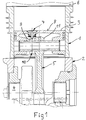
- a piston compressor essentially consists of a cylinder 1, a Crankcase 2, a piston 3, and a crankshaft 4 with a connecting rod 5.
- An uncomfortable The characteristic of the piston compressor is that it has negative torques has, which therefore stir that after exceeding the piston in the OT a Back expansion occurs. This causes gears when the compressor is driven very unpleasant gear noise due to flanking. To do this It is necessary to avoid the compression space between piston 3 and one To connect the cylinder head base 6 to the atmosphere via the crankcase 2.
- valve 7 which is in a piston crown 8 is arranged.
- This valve 7 is actuated by a cam 9, which itself on a cam disk 10, or also directly on a connecting rod eye 11 of the Connecting rod 5 is located.
- the cam disk 10 is connected in a rotationally fixed manner to the connecting rod eye 11.
- the function is to be said that the movement of the valve 7 from the pivoting movement of the connecting rod 5 is derived. This leads to the pivoting movement of the connecting rod 5
- Connecting rod eye 11 makes a rotary movement which is based on the rotation of the cam disk 10 and the cam 9 located thereon to raise the valve 7 in the area the TDC position of the piston 3 leads. Through this opening of the valve 7 in Compression room relaxes compressed air, so that a back expansion with the associated negative consequences are avoided.
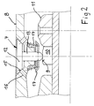
- Fig. 2 shows in detail an embodiment of the valve 7.
- the valve 7 consists of a Valve plate 12 and the associated valve stem 13.
- the valve plate 12 is by a compression spring 14 against a valve seat incorporated in the piston crown 15 pressed with holes 16.
- the compression spring 14 is supported against the piston crown 8 and a spring plate 17, which is connected to the valve stem 13.
- the valve 7 via the connecting rod eye 11 rotatably connected cam 10 with cam 9 raised.
- the in Compression room air is blown off through the holes 16, and thus avoiding re-expansion.
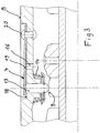
- FIG. 3 Another embodiment of the valve 7 is shown in FIG. 3.
- a membrane 19 is provided, which by means of rivets 20 is anchored to the piston crown 8.
- the membrane 19 closes the bore 16. If air is now to be blown off in the TDC position of the piston 3 (FIG. 1), then the Diaphragm 19 through the valve stem 13 by means of the cam 9 against the restoring force the compression spring 14 is raised and air escapes through the bore 16 in the piston crown 8, so that back expansion is avoided.
- the device according to the invention can be used in series production Piston compressor only by installing valve 7 and attaching one Cam 10 on the connecting rod head 11 converted to a low-noise operation become.
Landscapes
- Engineering & Computer Science (AREA)
- Mechanical Engineering (AREA)
- General Engineering & Computer Science (AREA)
- Compressor (AREA)
- Compressors, Vaccum Pumps And Other Relevant Systems (AREA)
Applications Claiming Priority (2)
| Application Number | Priority Date | Filing Date | Title |
|---|---|---|---|
| DE19743444 | 1997-10-01 | ||
| DE1997143444 DE19743444C2 (de) | 1997-10-01 | 1997-10-01 | Vorrichtung zur Vermeidung von Rückexpansion bei Kolbenverdichtern |
Publications (2)
| Publication Number | Publication Date |
|---|---|
| EP0907022A2 true EP0907022A2 (fr) | 1999-04-07 |
| EP0907022A3 EP0907022A3 (fr) | 2001-06-20 |
Family
ID=7844319
Family Applications (1)
| Application Number | Title | Priority Date | Filing Date |
|---|---|---|---|
| EP98117617A Withdrawn EP0907022A3 (fr) | 1997-10-01 | 1998-09-17 | Dispositif pour éviter des retours de détente gênants dans un compresseur à piston |
Country Status (2)
| Country | Link |
|---|---|
| EP (1) | EP0907022A3 (fr) |
| DE (1) | DE19743444C2 (fr) |
Families Citing this family (1)
| Publication number | Priority date | Publication date | Assignee | Title |
|---|---|---|---|---|
| DE102016114511A1 (de) | 2015-08-31 | 2017-03-02 | Martin Maeser | Hubkolbenmaschine mit Einlassventil im Kolbenboden |
Citations (1)
| Publication number | Priority date | Publication date | Assignee | Title |
|---|---|---|---|---|
| DE3902658A1 (de) | 1989-01-30 | 1990-08-02 | Knorr Bremse Ag | Kolbenmkompressor |
Family Cites Families (6)
| Publication number | Priority date | Publication date | Assignee | Title |
|---|---|---|---|---|
| DE229229C (fr) * | ||||
| GB248595A (en) * | 1925-05-13 | 1926-03-11 | Leon De Vooght | Improved air compressor |
| US1607478A (en) * | 1925-06-18 | 1926-11-16 | Prestage Edwin | Suction valve of air and gas compressors |
| DE3112386A1 (de) * | 1981-03-28 | 1982-12-02 | Fichtel & Sachs Ag, 8720 Schweinfurt | Verdichter |
| DE3514119A1 (de) * | 1985-04-19 | 1986-10-23 | Klöckner-Humboldt-Deutz AG, 5000 Köln | Verfahren zum betrieb eines kompressors mit wenigstens zwei zylindern sowie vorrichtung zur durchfuehrung des verfahrens |
| DE4018055A1 (de) * | 1990-06-06 | 1991-12-12 | Man Nutzfahrzeuge Ag | Verfahren zur verminderung von getriebegeraeuschen bei kolbenverdichtern, sowie vorrichtung zur durchfuehrung dieses verfahrens |
-
1997
- 1997-10-01 DE DE1997143444 patent/DE19743444C2/de not_active Expired - Fee Related
-
1998
- 1998-09-17 EP EP98117617A patent/EP0907022A3/fr not_active Withdrawn
Patent Citations (1)
| Publication number | Priority date | Publication date | Assignee | Title |
|---|---|---|---|---|
| DE3902658A1 (de) | 1989-01-30 | 1990-08-02 | Knorr Bremse Ag | Kolbenmkompressor |
Also Published As
| Publication number | Publication date |
|---|---|
| DE19743444C2 (de) | 1999-12-16 |
| EP0907022A3 (fr) | 2001-06-20 |
| DE19743444A1 (de) | 1999-04-08 |
Similar Documents
| Publication | Publication Date | Title |
|---|---|---|
| DE102010011454A1 (de) | Hubkolbenbrennkraftmaschine mit Dekompressionsmotorbremse | |
| DE102010011455A1 (de) | Hubkolbenbrennkraftmaschine mit einstellbarem Aufpumpelement | |
| DE19681400B4 (de) | Hydraulisches Abstützelement für eine Ventilsteuerung einer Brennkraftmaschine | |
| DE102005002542A1 (de) | Luftkompressor für Reifenfüllkombination | |
| DE102008052279A1 (de) | Schaltbares Bauteil für einen Ventiltrieb einer Brennkraftmaschine | |
| DE102007002787A1 (de) | Schaltbares Abstützelement für einen Ventiltrieb einer Brennkraftmaschine | |
| DE4213798C2 (de) | Radialkolbenpumpe, insbesondere Kraftstoffpumpe für Verbrennungsmotoren | |
| DE102007011892A1 (de) | Schaltbares Abstützelement für einen Ventiltrieb einer Brennkraftmaschine | |
| DE102011004403A1 (de) | Hydraulischer Ventiltrieb einer Brennkraftmaschine | |
| EP2038890A2 (fr) | Moteur à pistons axiaux comportant un disque appendice sur un disque de retenue, disque de retenue correspondant et disque appendice correspondant | |
| DE102004050076B4 (de) | Pneumatisch betriebenes Elektrowerkzeug mit einem Mechanismus zum Ändern des Druckluftdrucks | |
| DE1403954C3 (de) | Kompressor zum Fördern von Gas | |
| DE2245242C3 (de) | Mit Druckmittel betriebenes und durch ein Ventil gesteuertes Werkzeug | |
| DE60309280T2 (de) | Integriertes Ringventil für einen Kompressorkolben | |
| EP0907022A2 (fr) | Dispositif pour éviter des retours de détente gênants dans un compresseur à piston | |
| DE102008006045A1 (de) | Tablettenpresse | |
| EP0731273A2 (fr) | Piston avec tige de piston | |
| DE2745470B2 (de) | Pumpenventilkopf | |
| DE4100763A1 (de) | Vorrichtung zum betaetigen der ventile eines hubkolbenmotors | |
| DE19804084A1 (de) | Taumelscheibenverdichter mit variabler Fördermenge | |
| DE10355502A1 (de) | Vorrichtung zum Verändern der Steuerzeiten von Gaswechselventilen einer Brennkraftmaschine, insbesondere Rotationskolben-Verstelleinrichtung zur Drehwinkelverstellung einer Nockenwelle gegenüber einer Kurbelwelle | |
| DE112006002191B4 (de) | Hubkolbenmaschine mit einer Befestigung der Ventilplatte am Zylinderblock | |
| EP1036942A3 (fr) | Dispositif de commande pour un vérin | |
| DE2223999C2 (de) | Einlaß- und Auslaßventilanordnung für den Arbeitshubraum eines Druckluftnaglers | |
| DE10207038A1 (de) | Ventiltrieb für eine Brennkraftmaschine |
Legal Events
| Date | Code | Title | Description |
|---|---|---|---|
| PUAI | Public reference made under article 153(3) epc to a published international application that has entered the european phase |
Free format text: ORIGINAL CODE: 0009012 |
|
| AK | Designated contracting states |
Kind code of ref document: A2 Designated state(s): DE FR GB IT SE |
|
| AX | Request for extension of the european patent |
Free format text: AL;LT;LV;MK;RO;SI |
|
| PUAL | Search report despatched |
Free format text: ORIGINAL CODE: 0009013 |
|
| AK | Designated contracting states |
Kind code of ref document: A3 Designated state(s): AT BE CH CY DE DK ES FI FR GB GR IE IT LI LU MC NL PT SE |
|
| AX | Request for extension of the european patent |
Free format text: AL;LT;LV;MK;RO;SI |
|
| RIC1 | Information provided on ipc code assigned before grant |
Free format text: 7F 04B 39/00 A, 7F 04B 49/24 B |
|
| AKX | Designation fees paid |
Free format text: DE FR GB IT SE |
|
| STAA | Information on the status of an ep patent application or granted ep patent |
Free format text: STATUS: THE APPLICATION IS DEEMED TO BE WITHDRAWN |
|
| 18D | Application deemed to be withdrawn |
Effective date: 20011221 |