EP0907022A2 - Device for avoiding disturbing back expansion in a piston compressor - Google Patents
Device for avoiding disturbing back expansion in a piston compressor Download PDFInfo
- Publication number
- EP0907022A2 EP0907022A2 EP98117617A EP98117617A EP0907022A2 EP 0907022 A2 EP0907022 A2 EP 0907022A2 EP 98117617 A EP98117617 A EP 98117617A EP 98117617 A EP98117617 A EP 98117617A EP 0907022 A2 EP0907022 A2 EP 0907022A2
- Authority
- EP
- European Patent Office
- Prior art keywords
- valve
- piston
- connecting rod
- cam
- piston crown
- Prior art date
- Legal status (The legal status is an assumption and is not a legal conclusion. Google has not performed a legal analysis and makes no representation as to the accuracy of the status listed.)
- Withdrawn
Links
Images
Classifications
-
- F—MECHANICAL ENGINEERING; LIGHTING; HEATING; WEAPONS; BLASTING
- F04—POSITIVE - DISPLACEMENT MACHINES FOR LIQUIDS; PUMPS FOR LIQUIDS OR ELASTIC FLUIDS
- F04B—POSITIVE-DISPLACEMENT MACHINES FOR LIQUIDS; PUMPS
- F04B39/00—Component parts, details, or accessories, of pumps or pumping systems specially adapted for elastic fluids, not otherwise provided for in, or of interest apart from, groups F04B25/00 - F04B37/00
- F04B39/0005—Component parts, details, or accessories, of pumps or pumping systems specially adapted for elastic fluids, not otherwise provided for in, or of interest apart from, groups F04B25/00 - F04B37/00 adaptations of pistons
- F04B39/0016—Component parts, details, or accessories, of pumps or pumping systems specially adapted for elastic fluids, not otherwise provided for in, or of interest apart from, groups F04B25/00 - F04B37/00 adaptations of pistons with valve arranged in the piston
Definitions
- the invention relates to a device according to the preamble of the claim 1.
- the invention has for its object a device for avoiding To design back expansion so that one with the least possible construction effort gets along.
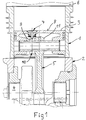
- a piston compressor essentially consists of a cylinder 1, a Crankcase 2, a piston 3, and a crankshaft 4 with a connecting rod 5.
- An uncomfortable The characteristic of the piston compressor is that it has negative torques has, which therefore stir that after exceeding the piston in the OT a Back expansion occurs. This causes gears when the compressor is driven very unpleasant gear noise due to flanking. To do this It is necessary to avoid the compression space between piston 3 and one To connect the cylinder head base 6 to the atmosphere via the crankcase 2.
- valve 7 which is in a piston crown 8 is arranged.
- This valve 7 is actuated by a cam 9, which itself on a cam disk 10, or also directly on a connecting rod eye 11 of the Connecting rod 5 is located.
- the cam disk 10 is connected in a rotationally fixed manner to the connecting rod eye 11.
- the function is to be said that the movement of the valve 7 from the pivoting movement of the connecting rod 5 is derived. This leads to the pivoting movement of the connecting rod 5
- Connecting rod eye 11 makes a rotary movement which is based on the rotation of the cam disk 10 and the cam 9 located thereon to raise the valve 7 in the area the TDC position of the piston 3 leads. Through this opening of the valve 7 in Compression room relaxes compressed air, so that a back expansion with the associated negative consequences are avoided.
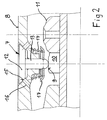
- Fig. 2 shows in detail an embodiment of the valve 7.
- the valve 7 consists of a Valve plate 12 and the associated valve stem 13.
- the valve plate 12 is by a compression spring 14 against a valve seat incorporated in the piston crown 15 pressed with holes 16.
- the compression spring 14 is supported against the piston crown 8 and a spring plate 17, which is connected to the valve stem 13.
- the valve 7 via the connecting rod eye 11 rotatably connected cam 10 with cam 9 raised.
- the in Compression room air is blown off through the holes 16, and thus avoiding re-expansion.
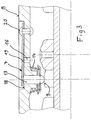
- FIG. 3 Another embodiment of the valve 7 is shown in FIG. 3.
- a membrane 19 is provided, which by means of rivets 20 is anchored to the piston crown 8.
- the membrane 19 closes the bore 16. If air is now to be blown off in the TDC position of the piston 3 (FIG. 1), then the Diaphragm 19 through the valve stem 13 by means of the cam 9 against the restoring force the compression spring 14 is raised and air escapes through the bore 16 in the piston crown 8, so that back expansion is avoided.
- the device according to the invention can be used in series production Piston compressor only by installing valve 7 and attaching one Cam 10 on the connecting rod head 11 converted to a low-noise operation become.
Landscapes
- Engineering & Computer Science (AREA)
- Mechanical Engineering (AREA)
- General Engineering & Computer Science (AREA)
- Compressor (AREA)
- Compressors, Vaccum Pumps And Other Relevant Systems (AREA)
Abstract
Description
Die Erfindung bezieht sich auf eine Vorrichtung gemäß dem Gattungsbegriff des Patentanspruches
1.The invention relates to a device according to the preamble of the
Zur Vermeidung negativer Drehmomente als Folge von Rückexpansion ist es bekannt, bei Kolbenverdichtern die Möglichkeit vorzuseher, daß im Bereich von OT-Stellung des Kolbens der Verdichtungsraum mit der Atmosphare verbunden wird. Zu diesem Zweck werden im Zylinder über den Umfang verteilte Axialnuten vorgesehen, welche in der Nahe des OT den Verdichtungsraum über eine Ringnut im Kolben und einen Hohlraum im Kolben zum Druckausgleich mit der Umgebung verbinden. Eine derartige Vorrichtung zur Vermeidung der Rückexpansion hat den Nachteil, daß an einem bestehenden Verdichter erhebliche bauliche Veränderungen vorgenommen werden müssen. ( DE 39 02 658 A1)To avoid negative torques as a result of back expansion, it is known with piston compressors, the possibility to foresee that in the area of TDC position the piston the compression chamber is connected to the atmosphere. To this Purpose are provided in the cylinder over the circumference distributed axial grooves near the TDC the compression chamber via an annular groove in the piston and one Connect the cavity in the piston to the environment to equalize the pressure. Such Device to avoid back expansion has the disadvantage that at one existing compressor significant structural changes can be made have to. (DE 39 02 658 A1)
Der Erfindung liegt die Aufgabe zugrunde eine Vorrichtung zur Vermeidung von Rückexpansion so zu gestalten, daß man mit möglichst geringem baulichen Aufwand auskommt.The invention has for its object a device for avoiding To design back expansion so that one with the least possible construction effort gets along.
Gelöst wird diese Aufgabe durch die kennzeichnenden Merkmale des Patentanspruches
1.This object is achieved by the characterizing features of the
Durch das im Kolbenboden eingebaute Ventil und dessen Betätigung durch einen mit dem Pleuelauge verbundenen Nocken läßt sich eine Rückexpansion an bestehenden Verdichtern mit geringem baulichen Aufwand verwirklichen.Through the valve built into the piston crown and its actuation by a the cam connected to the connecting rod eye can be re-expanded to existing ones Realize compressors with little construction effort.
Vorteilhafte Weiterbildungen sind den Unteransprüchen 2 bis 5 zu entnehmen. Advantageous further developments can be found in
Ein Ausführungsbeispiel der Erfindung ist an Hand von Zeichnungen dargestellt. Es zeigt:
- Fig. 1
- einen Längsschnitt durch einen Kolbenverdichter
- Fig. 2
- ein Detail eines Ventils mit Ventilteller
- Fig. 3
- ein Detail eines Ventils mit einer Membran
- Fig. 1
- a longitudinal section through a piston compressor
- Fig. 2
- a detail of a valve with valve disk
- Fig. 3
- a detail of a valve with a membrane
Ein Kolbenverdichter besteht nach Fig. 1 im wesentlichen aus einem Zylinder 1, einem
Kurbelgehäuse 2, einem Kolben 3, sowie einer Kurbelwelle 4 mit Pleuel 5. Eine unangenehme
Eigenschaft des Kolbenverdichters ist darin zu sehen, daß er negative Drehmomente
aufweist, die daher rühren, daß nach Überschreiten des Kolbens im OT eine
Rückexpansion auftritt. Diese verursacht bei Antrieb des Verdichters mittels Zahnrädern
durch das Flankenschlagen sehr unangenehme Getriebegeräusche. Um dies zu
vermeiden ist es erforderlich, den Kompressionsraum zwischen Kolben 3 und einem
Zylinderkopfboden 6 über das Kurbelgehäuse 2 mit der Atmosphäre zu verbinden.According to FIG. 1, a piston compressor essentially consists of a
Erfindungsgemäß wird dies mit einem Ventil 7 bewerkstelligt, welches in einem Kolbenboden
8 angeordnet ist. Betätigt wird dieses Ventil 7 durch einen Nocken 9, welcher
sich auf einer Nockenscheibe 10, oder auch direkt auf einem Pleuelauge 11 des
Pleuels 5 befindet. Die Nockenscheibe 10 ist drehfest mit dem Pleuelauge 11 verbunden.According to the invention, this is accomplished with a
Zur Funktion ist zu sagen, daß die Bewegung des Ventils 7 von der Schwenkbewegung
des Pleuel 5 abgeleitet wird. Durch die Schwenkbewegung des Pleuels 5 führt das
Pleuelauge 11 eine Drehbewegung aus, die über die Drehung der Nockenscheibe 10
und des darauf befindlichen Nockens 9 zu einer Anhebung des Ventils 7 im Bereich
der OT-Stellung des Kolbens 3 führt. Durch diese Öffnung des Ventils 7 wird die im
Kompressionsraum verdichtete Luft entspannt, so daß eine Rückexpansion mit den
damit verbundenen negativen Folgen vermieden wird. The function is to be said that the movement of the
Fig. 2 zeigt im Detail eine Ausführung des Ventils 7. Das Ventil 7 besteht aus einem
Ventilteller 12 und dem damit verbundenen Ventilschaft 13. Der Ventilteller 12 wird
durch eine Druckfeder 14 gegen einen in den Kolbenboden eingearbeiteten Ventilsitz
15 mit Bohrungen 16 gepreßt. Die Druckfeder 14 stützt sich gegen Kolbenboden 8 und
einen Federteller 17 ab, welcher mit dem Ventilschaft 13 verbunden ist. Im Bereich
der OT-Stellung des Kolbens 3 ( Fig. 1 ) wird das Ventil 7 über die mit dem Pleuelauge
11 drehfest verbundene Nockenscheibe 10 mit Nocken 9 angehoben. Die im
Kompressionsraum befindliche Luft wird über die Bohrungen 16 abgeblasen, und
damit eine Rückexpansion vermieden.Fig. 2 shows in detail an embodiment of the
Eine weitere Ausführungsform des Ventils 7 ist in Fig. 3 dargestellt. In einer Ausnehmung
18 im Kolbenboden 8 ist eine Membran 19 vorgesehen, welche mittels Niete
20 mit dem Kolbenboden 8 verankert ist. Die Membran 19 verschließt die Bohrung 16.
Soll nun in OT-Stellung des Kolbens 3 ( Fig. 1 ) Luft abgeblasen werden, so wird die
Membran 19 durch den Ventilschaft 13 mittels des Nockens 9 gegen die Rückstellkraft
der Druckfeder 14 angehoben und Luft entweicht über die Bohrung 16 im Kolbenboden
8, so daß wiederum Rückexpansion vermieden wird.Another embodiment of the
Durch die erfindungsgemäße Vorrichtung können in Serienherstellung befindliche
Kolbenverdichter nur durch den Einbau des Ventils 7 und die Anbringung einer
Nockenscheibe 10 am Pleuelkopf 11 auf einen geräuscharmen Betrieb umgerüstet
werden.The device according to the invention can be used in series production
Piston compressor only by installing
Claims (5)
Applications Claiming Priority (2)
| Application Number | Priority Date | Filing Date | Title |
|---|---|---|---|
| DE19743444 | 1997-10-01 | ||
| DE1997143444 DE19743444C2 (en) | 1997-10-01 | 1997-10-01 | Device for avoiding back expansion in piston compressors |
Publications (2)
| Publication Number | Publication Date |
|---|---|
| EP0907022A2 true EP0907022A2 (en) | 1999-04-07 |
| EP0907022A3 EP0907022A3 (en) | 2001-06-20 |
Family
ID=7844319
Family Applications (1)
| Application Number | Title | Priority Date | Filing Date |
|---|---|---|---|
| EP98117617A Withdrawn EP0907022A3 (en) | 1997-10-01 | 1998-09-17 | Device for avoiding disturbing back expansion in a piston compressor |
Country Status (2)
| Country | Link |
|---|---|
| EP (1) | EP0907022A3 (en) |
| DE (1) | DE19743444C2 (en) |
Families Citing this family (1)
| Publication number | Priority date | Publication date | Assignee | Title |
|---|---|---|---|---|
| DE102016114511A1 (en) | 2015-08-31 | 2017-03-02 | Martin Maeser | Reciprocating engine with inlet valve in the piston head |
Citations (1)
| Publication number | Priority date | Publication date | Assignee | Title |
|---|---|---|---|---|
| DE3902658A1 (en) | 1989-01-30 | 1990-08-02 | Knorr Bremse Ag | Piston compressor |
Family Cites Families (6)
| Publication number | Priority date | Publication date | Assignee | Title |
|---|---|---|---|---|
| DE229229C (en) * | ||||
| GB248595A (en) * | 1925-05-13 | 1926-03-11 | Leon De Vooght | Improved air compressor |
| US1607478A (en) * | 1925-06-18 | 1926-11-16 | Prestage Edwin | Suction valve of air and gas compressors |
| DE3112386A1 (en) * | 1981-03-28 | 1982-12-02 | Fichtel & Sachs Ag, 8720 Schweinfurt | Compressor |
| DE3514119A1 (en) * | 1985-04-19 | 1986-10-23 | Klöckner-Humboldt-Deutz AG, 5000 Köln | Method for operating a compressor having at least two cylinders, and device for implementing the method |
| DE4018055A1 (en) * | 1990-06-06 | 1991-12-12 | Man Nutzfahrzeuge Ag | METHOD FOR REDUCING GEARBOX NOISE IN PISTON COMPRESSORS, AND DEVICE FOR CARRYING OUT THIS METHOD |
-
1997
- 1997-10-01 DE DE1997143444 patent/DE19743444C2/en not_active Expired - Fee Related
-
1998
- 1998-09-17 EP EP98117617A patent/EP0907022A3/en not_active Withdrawn
Patent Citations (1)
| Publication number | Priority date | Publication date | Assignee | Title |
|---|---|---|---|---|
| DE3902658A1 (en) | 1989-01-30 | 1990-08-02 | Knorr Bremse Ag | Piston compressor |
Also Published As
| Publication number | Publication date |
|---|---|
| DE19743444C2 (en) | 1999-12-16 |
| DE19743444A1 (en) | 1999-04-08 |
| EP0907022A3 (en) | 2001-06-20 |
Similar Documents
| Publication | Publication Date | Title |
|---|---|---|
| DE102010011454A1 (en) | Reciprocating internal combustion engine with decompression engine brake | |
| DE102010011455A1 (en) | Reciprocating internal combustion engine with adjustable inflating element | |
| DE19681400B4 (en) | Hydraulic support element for a valve control of an internal combustion engine | |
| DE102005002542A1 (en) | Air compressor for tire filling combination | |
| DE102008052279A1 (en) | Switchable component for a valve train of an internal combustion engine | |
| DE102007002787A1 (en) | Switchable support element for a valve train of an internal combustion engine | |
| DE4213798C2 (en) | Radial piston pump, in particular fuel pump for internal combustion engines | |
| DE102007011892A1 (en) | Switchable support element for a valve train of an internal combustion engine | |
| DE102011004403A1 (en) | Hydraulic valve train of an internal combustion engine | |
| EP2038890A2 (en) | Axial piston machine comprising an additional disk on a retaining disk, corresponding retaining disk and corresponding additional disk | |
| DE102013021913B4 (en) | Automatic pressure drain pump | |
| DE102004050076B4 (en) | Pneumatically operated power tool with a mechanism for changing the compressed air pressure | |
| EP1636474A2 (en) | Method for producing a one-piece piston for an internal combustion engine | |
| DE1403954C3 (en) | Compressor for pumping gas | |
| DE2245242C3 (en) | Tool operated with pressure medium and controlled by a valve | |
| DE60309280T2 (en) | Integrated ring valve for a compressor piston | |
| DE102008006045A1 (en) | tablet press | |
| EP0731273A2 (en) | Piston with piston rod | |
| DE19743444A1 (en) | Device for avoiding back expansion in piston compressors | |
| DE2745470B2 (en) | Pump valve head | |
| DE4100763A1 (en) | DEVICE FOR ACTUATING THE VALVES OF A PISTON PISTON ENGINE | |
| DE19804084A1 (en) | Swash plate compressor with variable capacity | |
| DE10355502A1 (en) | System for controlling timing of IC engine especially radial piston type engine has a camshaft mounted wheel with hydraulic ducts inside an outer drive wheel connected to the crankshaft | |
| DE1001593B (en) | Swash plate pump with automatic pressure-dependent feed control | |
| EP1036942A3 (en) | Control device for a cylinder |
Legal Events
| Date | Code | Title | Description |
|---|---|---|---|
| PUAI | Public reference made under article 153(3) epc to a published international application that has entered the european phase |
Free format text: ORIGINAL CODE: 0009012 |
|
| AK | Designated contracting states |
Kind code of ref document: A2 Designated state(s): DE FR GB IT SE |
|
| AX | Request for extension of the european patent |
Free format text: AL;LT;LV;MK;RO;SI |
|
| PUAL | Search report despatched |
Free format text: ORIGINAL CODE: 0009013 |
|
| AK | Designated contracting states |
Kind code of ref document: A3 Designated state(s): AT BE CH CY DE DK ES FI FR GB GR IE IT LI LU MC NL PT SE |
|
| AX | Request for extension of the european patent |
Free format text: AL;LT;LV;MK;RO;SI |
|
| RIC1 | Information provided on ipc code assigned before grant |
Free format text: 7F 04B 39/00 A, 7F 04B 49/24 B |
|
| AKX | Designation fees paid |
Free format text: DE FR GB IT SE |
|
| STAA | Information on the status of an ep patent application or granted ep patent |
Free format text: STATUS: THE APPLICATION IS DEEMED TO BE WITHDRAWN |
|
| 18D | Application deemed to be withdrawn |
Effective date: 20011221 |