EP0906596B1 - Prozessautomatisierungssystem - Google Patents
Prozessautomatisierungssystem Download PDFInfo
- Publication number
- EP0906596B1 EP0906596B1 EP97931629A EP97931629A EP0906596B1 EP 0906596 B1 EP0906596 B1 EP 0906596B1 EP 97931629 A EP97931629 A EP 97931629A EP 97931629 A EP97931629 A EP 97931629A EP 0906596 B1 EP0906596 B1 EP 0906596B1
- Authority
- EP
- European Patent Office
- Prior art keywords
- module
- communication
- process automation
- technology
- specific information
- Prior art date
- Legal status (The legal status is an assumption and is not a legal conclusion. Google has not performed a legal analysis and makes no representation as to the accuracy of the status listed.)
- Revoked
Links
Images
Classifications
-
- G—PHYSICS
- G05—CONTROLLING; REGULATING
- G05B—CONTROL OR REGULATING SYSTEMS IN GENERAL; FUNCTIONAL ELEMENTS OF SUCH SYSTEMS; MONITORING OR TESTING ARRANGEMENTS FOR SUCH SYSTEMS OR ELEMENTS
- G05B19/00—Program-control systems
- G05B19/02—Program-control systems electric
- G05B19/418—Total factory control, i.e. centrally controlling a plurality of machines, e.g. direct or distributed numerical control [DNC], flexible manufacturing systems [FMS], integrated manufacturing systems [IMS] or computer integrated manufacturing [CIM]
- G05B19/41845—Total factory control, i.e. centrally controlling a plurality of machines, e.g. direct or distributed numerical control [DNC], flexible manufacturing systems [FMS], integrated manufacturing systems [IMS] or computer integrated manufacturing [CIM] characterised by system universality, reconfigurability, modularity
-
- G—PHYSICS
- G05—CONTROLLING; REGULATING
- G05B—CONTROL OR REGULATING SYSTEMS IN GENERAL; FUNCTIONAL ELEMENTS OF SUCH SYSTEMS; MONITORING OR TESTING ARRANGEMENTS FOR SUCH SYSTEMS OR ELEMENTS
- G05B2219/00—Program-control systems
- G05B2219/30—Nc systems
- G05B2219/31—From computer integrated manufacturing till monitoring
- G05B2219/31094—Data exchange between modules, cells, devices, processors
-
- G—PHYSICS
- G05—CONTROLLING; REGULATING
- G05B—CONTROL OR REGULATING SYSTEMS IN GENERAL; FUNCTIONAL ELEMENTS OF SUCH SYSTEMS; MONITORING OR TESTING ARRANGEMENTS FOR SUCH SYSTEMS OR ELEMENTS
- G05B2219/00—Program-control systems
- G05B2219/30—Nc systems
- G05B2219/31—From computer integrated manufacturing till monitoring
- G05B2219/31226—Multitasking server connected to general network and to nc machines
-
- G—PHYSICS
- G05—CONTROLLING; REGULATING
- G05B—CONTROL OR REGULATING SYSTEMS IN GENERAL; FUNCTIONAL ELEMENTS OF SUCH SYSTEMS; MONITORING OR TESTING ARRANGEMENTS FOR SUCH SYSTEMS OR ELEMENTS
- G05B2219/00—Program-control systems
- G05B2219/30—Nc systems
- G05B2219/33—Director till display
- G05B2219/33121—Host loads program from attached module to control that module
-
- G—PHYSICS
- G05—CONTROLLING; REGULATING
- G05B—CONTROL OR REGULATING SYSTEMS IN GENERAL; FUNCTIONAL ELEMENTS OF SUCH SYSTEMS; MONITORING OR TESTING ARRANGEMENTS FOR SUCH SYSTEMS OR ELEMENTS
- G05B2219/00—Program-control systems
- G05B2219/30—Nc systems
- G05B2219/33—Director till display
- G05B2219/33273—DCS distributed, decentralised controlsystem, multiprocessor
-
- G—PHYSICS
- G05—CONTROLLING; REGULATING
- G05B—CONTROL OR REGULATING SYSTEMS IN GENERAL; FUNCTIONAL ELEMENTS OF SUCH SYSTEMS; MONITORING OR TESTING ARRANGEMENTS FOR SUCH SYSTEMS OR ELEMENTS
- G05B2219/00—Program-control systems
- G05B2219/30—Nc systems
- G05B2219/33—Director till display
- G05B2219/33282—Node with communication, transducer, common core, application specific modules
-
- G—PHYSICS
- G05—CONTROLLING; REGULATING
- G05B—CONTROL OR REGULATING SYSTEMS IN GENERAL; FUNCTIONAL ELEMENTS OF SUCH SYSTEMS; MONITORING OR TESTING ARRANGEMENTS FOR SUCH SYSTEMS OR ELEMENTS
- G05B2219/00—Program-control systems
- G05B2219/30—Nc systems
- G05B2219/45—Nc applications
- G05B2219/45226—Process control
-
- Y—GENERAL TAGGING OF NEW TECHNOLOGICAL DEVELOPMENTS; GENERAL TAGGING OF CROSS-SECTIONAL TECHNOLOGIES SPANNING OVER SEVERAL SECTIONS OF THE IPC; TECHNICAL SUBJECTS COVERED BY FORMER USPC CROSS-REFERENCE ART COLLECTIONS [XRACs] AND DIGESTS
- Y02—TECHNOLOGIES OR APPLICATIONS FOR MITIGATION OR ADAPTATION AGAINST CLIMATE CHANGE
- Y02P—CLIMATE CHANGE MITIGATION TECHNOLOGIES IN THE PRODUCTION OR PROCESSING OF GOODS
- Y02P90/00—Enabling technologies with a potential contribution to greenhouse gas [GHG] emissions mitigation
- Y02P90/02—Total factory control, e.g. smart factories, flexible manufacturing systems [FMS] or integrated manufacturing systems [IMS]
Definitions
- the invention relates to a process automation system according to the preamble of claim 1.
- Such a process automation system is from the US-A-4 819 149.
- Process automation systems are usually hierarchical from a top operating and monitoring level, including management or management level, via automation levels structured down to the lowest sensor / actuator level.
- the Communication between the automation blocks in the individual automation levels take place via bus systems, whereby but especially in the lowest automation level still a high degree of conventional connection structures is to be found, so that in the construction of plants a high Cabling effort arises.
- bus systems whereby but especially in the lowest automation level still a high degree of conventional connection structures is to be found, so that in the construction of plants a high Cabling effort arises.
- Bus systems whereby but especially in the lowest automation level still a high degree of conventional connection structures is to be found, so that in the construction of plants a high Cabling effort arises.
- Bus systems whereby but especially in the lowest automation level still a high degree of conventional connection structures is to be found, so that in the construction of plants a high Cabling effort arises.
- too Coupling of sensors and actuators bus systems used (Siemens, Engineering & Automation, 1/95, pages 10,
- the programming and commissioning of the automation modules and the facilities in the operating and monitoring level can be done in different ways.
- the automation modules are first individually programmed. Then the Operating and monitoring level and then communication between the automation blocks and the operator control and monitoring level programmed. The programming is however time consuming and error prone.
- the automation modules can be used with one Tool can be programmed and then the programming data into a tool for programming the operating and Observation level. This approach requires a program file of the automation blocks is present.
- the invention has for its object a process automation system to create, that without large programming and commissioning effort and subsequently can change or expand.
- the object is achieved in that in claim 1 called process automation systems solved.
- functions are one Controller, a setpoint generator, a sensor (actual value generator) and an actuator (actuator).
- the module-specific information initially include the respective function of the technology module, so z. B. controller, and its integration into the measurement, Control and regulation system, i.e. the addresses of other technology modules, here the addresses of the setpoint generator and actual value generator, from which the controller receives its input values, and the address of the actuator to be influenced by the controller. It also contains the module-specific information Information about the respective device type, manufacturer etc.
- the saved module-specific information will be from the communication unit of the respective technology module via the data bus to the communication device transferred and there for quick access by the Operating and monitoring device saved.
- the operating and Observation facility can so on the information all technology modules connected to the data bus access and this information automatically its Add user and monitoring interface or with the corresponding one Average the operating and monitoring interface based on the module-specific information.
- this information can be the easiest way to create from the process-related area, change or expand.
- Module-specific information can be advantageous Additional plant-specific via a service interface Information in the communication device enter and save.
- An example of this are at a building automation system Information about the division of space involved in the creation of the operating and monitoring interface incorporated.
- the technology modules can preferably use their communication units and the data bus function-relevant data exchange with each other. So the controller mentioned above in this way the setpoint from the setpoint generator and the Actual value received from the actual value generator and in turn one Issue control command to the actuator.
- the technology modules Have input and / or output connections for direct Transmission of the functionally relevant data and sizes mentioned are interconnected by means of lines.
- the operator control and monitoring device can be operated via a remote bus, this is e.g. B. also a telephone network or a wireless To count data transmission path on the communication device be connected. So it is simple Way possible, the automation system or more similar automation systems on different To operate and monitor locations from a central location. An example of this is building automation with a central operating and monitoring device and different Automation systems for different Building.
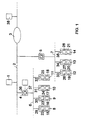
- Figure 1 shows a process automation system with a Operating and monitoring device 1, which in the present case Authorization via a long-distance bus 2, here generally a data transmission system, z. B. with telephone network 3, on each of 2 devices connected to the remote bus 4, 5 (network interface controller) can access.
- a long-distance bus 2 here generally a data transmission system, z. B. with telephone network 3, on each of 2 devices connected to the remote bus 4, 5 (network interface controller) can access.
- 5 network interface controller
- Each of the technology modules 8 to 14 contains means 15 to 21 for the automatic execution of a predetermined Function; in the case of the technology modules 8, 9, 10 shown and 11 these are the functions: controller, setpoint generator, Actuator and actual value transmitter.
- each technology module 8 to 14 contains one Memories 22 to 28, in which module-specific information, like the respective function of the technology module 8 to 14 and its integration into the measurement, control and regulation system, ie its interaction with other technology modules, saved are.
- this is the information "Controller” and the addresses of setpoint generator 9 and actual value transmitter 11, from which the controller receives 8 setpoints and actual values, and the address of the actuator 10, which is from the controller 8th is controlled depending on the control deviation.
- the Actual value transmitter 11 contains the information "actual value transmitter” as well the address of the controller 8 to which it delivers the actual value.
- Further stored module-specific information is the respective device type, manufacturer, version, etc.
- All technology modules 8 to 14 also contain communication units 29 to 35, through which they are assigned to the Data bus 6, 7 are connected.
- the individual technology modules 8 to 11 via their communication units 29 to 32 and the data bus 6 functionally relevant data with each other out.
- the controller 8 thus receives the setpoint from the setpoint generator 9 and from the actual value transmitter 11 the actual value and calculated from this a manipulated variable which he supplies to the actuator 10.
- Forwarding between two communication devices 4, 5 is usually a process function that is permanently in the communication device can be stored.
- the Forwarding to one of the operating and monitoring devices 1, 38 is done by selecting an operator.
- a Temporary storage of current process data in the communication device 4, 5 is in principle possible because of of the required storage space is not provided here.
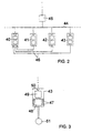
- FIG. 2 shows the connection of technology modules 40 to 43 via a data bus 44 with a communication device 45.
- the functionally relevant data and sizes in the case of the embodiment of Figure 1 between the individual Technology modules 8 to 11 via their communication units 29 to 32 and the data bus 6 are transmitted here via separate line connections 46 between the technology modules 40 to 43 involved.
- this includes, for example, the technology module 43 a predetermined number of input and output connections 47, each separately as a binary or analog Input or output can be used.
- This one and only Output connections 47 are the means 48 for execution assigned to the module-specific function.
- the module-specific Information storage is at 49 and the communication unit designated 50.
- the function of the Technology module 43 shown is that of an actual value transmitter, which is why the technology module 43 is equipped with a sensor 51 and forms a structural unit with it. About that In addition, it is also possible to place the sensor outside to provide the technology module 43 and with a line to connect one of the input terminals 47.
Landscapes
- Engineering & Computer Science (AREA)
- General Engineering & Computer Science (AREA)
- Manufacturing & Machinery (AREA)
- Quality & Reliability (AREA)
- Physics & Mathematics (AREA)
- General Physics & Mathematics (AREA)
- Automation & Control Theory (AREA)
- Testing And Monitoring For Control Systems (AREA)
- Control By Computers (AREA)
- Arrangements For Transmission Of Measured Signals (AREA)
- Computer And Data Communications (AREA)
- Small-Scale Networks (AREA)
- General Factory Administration (AREA)
Description
- Figur 1
- ein Beispiel des erfindungsgemäßen Automatisierungssystems in Form eines Blockschaltbildes,
- Figur 2
- eine alternative Ausbildung des die Technologiemodule betreffenden Teils des Automatisierungssystems und
- Figur 3
- ein Blockschaltbild eines Technologiemoduls.
Claims (7)
- Prozeßautomatisierungssystem zur Realisierung einer Meß-, Steuer- und Regelanlage, mit einer Bedien- und Beobachtungseinrichtung (1), die über eine Kommunikationseinrichtung (4) mit einem Datenbus (6) verbunden ist, an dem prozeßnahe Technologiemodule (8 bis 11) angeschlossen sind, die Mittel (15 bis 18) zur selbständigen Ausführung vorgegebener Funktionen im Rahmen der Prozeßautomatisierung aufweisen, wobei jedes Technologiemodul (8 bis 11) einen Speicher (22 bis 25) aufweist, in dem modulspezifische Informationen über die jeweilige Funktion des Technologiemoduls (8 bis 11) enthalten sind und wobei ferner jedes Technologiemodul (8 bis 11) eine Kommunikationseinheit (29 bis 32) enthält, über die es an den Datenbus (6) angeschlossen ist, dadurch gekennzeichnet, daß in dem Speicher (22 bis 25) außerdem modulspezifische Informationen über die jeweilige Einbindung des Technologiemoduls (8 bis 11) in die Meß-, Steuer- und Regelanlage enthalten sind und daß die Kommunikationseinheit (29 bis 32) dazu ausgebildet ist, während einer Initialisierungsphase die modulspezifischen Informationen an die Kommunikationseinrichtung (4) zu übertragen, in der diese Informationen für einen Zugriff durch die Bedien- und Beobachtungseinrichtung (1) gespeichert werden.
- Prozeßautomatisierungssystem nach Anspruch 1, dadurch gekennzeichnet, daß die Kommunikationseinrichtung (4) eine Service-Schnittstelle (37) zur Eingabe und Abspeicherung zusätzlicher, anlagenspezifischer Informationen aufweist.
- Prozeßautomatisierungssystem nach Anspruch 1 oder 2, dadurch gekennzeichnet, daß die Bedien- und Beobachtungseinrichtung (1) Mittel zur Erstellung einer Bedien- und Beobachtungsoberfläche aus den in der Kommunikationseinrichtung (4) gespeicherten modulspezifischen Informationen aufweist.
- Prozeßautomatisierungssystem nach Anspruch 2, dadurch gekennzeichnet, daß die Bedien- und Beobachtungseinrichtung (1) Mittel zur Erstellung einer Bedien- und Beobachtungsoberfläche aus den in der Kommunikationseinrichtung (4) gespeicherten modulspezifischen Informationen und den anlagenspezifischen Informationen aufweist.
- Prozeßautomatisierungssystem nach einem der vorangehenden Ansprüche, dadurch gekennzeichnet, daß die Kommunikationseinheiten (29 bis 32) zumindest einiger der Technologiemodule (8 bis 11) zum Austausch funktionsrelevanter Daten über den Datenbus (6) ausgebildet sind.
- Prozeßautomatisierungssystem nach einem der vorangehenden Ansprüche, dadurch gekennzeichnet, daß die Mittel zur Funktionsausübung zumindest einiger Technologiemodule (40 bis 43).Ein- und/oder Ausgangsanschlüsse (47) zum Austausch funktionsrelevanter Daten und/oder Größen über Leitungsverbindungen (46) zwischen den Technologiemodulen (40 bis 43) aufweisen.
- Prozeßautomatisierungssystem nach einem der vorangehenden Ansprüche, dadurch gekennzeichnet, daß die Bedien- und Beobachtungseinrichtung über einen Fernbus (2) an der Kommunikationseinrichtung (4) angeschlossen ist.
Applications Claiming Priority (3)
| Application Number | Priority Date | Filing Date | Title |
|---|---|---|---|
| DE19624929 | 1996-06-21 | ||
| DE19624929A DE19624929C2 (de) | 1996-06-21 | 1996-06-21 | Prozeßautomatisierungssystem |
| PCT/DE1997/001282 WO1997050025A1 (de) | 1996-06-21 | 1997-06-20 | Prozessautomatisierungssystem |
Publications (2)
| Publication Number | Publication Date |
|---|---|
| EP0906596A1 EP0906596A1 (de) | 1999-04-07 |
| EP0906596B1 true EP0906596B1 (de) | 2004-05-26 |
Family
ID=7797656
Family Applications (1)
| Application Number | Title | Priority Date | Filing Date |
|---|---|---|---|
| EP97931629A Revoked EP0906596B1 (de) | 1996-06-21 | 1997-06-20 | Prozessautomatisierungssystem |
Country Status (6)
| Country | Link |
|---|---|
| US (1) | US6473656B1 (de) |
| EP (1) | EP0906596B1 (de) |
| AT (1) | ATE268017T1 (de) |
| DE (2) | DE19624929C2 (de) |
| ES (1) | ES2221689T3 (de) |
| WO (1) | WO1997050025A1 (de) |
Families Citing this family (94)
| Publication number | Priority date | Publication date | Assignee | Title |
|---|---|---|---|---|
| US7254518B2 (en) | 1996-03-28 | 2007-08-07 | Rosemount Inc. | Pressure transmitter with diagnostics |
| US7949495B2 (en) | 1996-03-28 | 2011-05-24 | Rosemount, Inc. | Process variable transmitter with diagnostics |
| US7623932B2 (en) | 1996-03-28 | 2009-11-24 | Fisher-Rosemount Systems, Inc. | Rule set for root cause diagnostics |
| US6654697B1 (en) | 1996-03-28 | 2003-11-25 | Rosemount Inc. | Flow measurement with diagnostics |
| US8290721B2 (en) | 1996-03-28 | 2012-10-16 | Rosemount Inc. | Flow measurement diagnostics |
| US7630861B2 (en) | 1996-03-28 | 2009-12-08 | Rosemount Inc. | Dedicated process diagnostic device |
| DE19814611A1 (de) † | 1998-04-01 | 1999-10-07 | Bosch Gmbh Robert | Bussystem, insbesondere für eine Hausautomatisierungseinrichtung |
| DE19818041B4 (de) * | 1998-04-22 | 2008-04-03 | Siemens Ag | Verfahren zur Erzeugung einer Oberfläche zum Bedienen und Beobachten von Leitsystemen |
| SE9801863L (sv) | 1998-05-27 | 1999-11-28 | Abb Ab | Anläggning för styrande av processutrustning |
| DE19857649A1 (de) | 1998-12-14 | 2000-06-15 | Siemens Ag | Verteiltes Steuerungssystem sowie Anlagenkomponente für ein derartiges System |
| DE19910311A1 (de) * | 1999-03-09 | 2000-09-14 | Siemens Ag | Automatisierungssystem mit wiederverwendbaren Automatisierungsobjekten und Verfahren zur Wiederverwendung von Automatisierungslösungen in Engineering-Werkzeugen |
| US7010459B2 (en) | 1999-06-25 | 2006-03-07 | Rosemount Inc. | Process device diagnostics using process variable sensor signal |
| JP2001038663A (ja) * | 1999-07-28 | 2001-02-13 | Yamaha Motor Co Ltd | マシンの制御システム |
| DE29914463U1 (de) * | 1999-08-20 | 2000-09-28 | Siemens AG, 80333 München | Projektierungseinheit für korrespondierende Diagnosedatensätze eines Systems mit Steuerungseinheit und Bedien- und/oder Beobachtungseinheit, und System mit Mitteln zum Versionsvergleich von zugeordneten Diagnosedatensätzen |
| EP1096348B1 (de) * | 1999-11-01 | 2005-01-12 | Abb Research Ltd. | Integration eines Feldleitgerätes in ein Anlagenleitsystem |
| WO2001046764A1 (de) * | 1999-12-21 | 2001-06-28 | Siemens Aktiengesellschaft | Einrichtung zur projektierung von automatisierungssystemen |
| AU4227501A (en) * | 2000-03-01 | 2001-09-12 | Siemens Aktiengesellschaft | Method and device for processing data of an automation system for a building system engineering installation |
| DE10012579B4 (de) * | 2000-03-15 | 2006-04-20 | Teamtechnik Maschinen Und Anlagen Gmbh | Bearbeitungsstation und Verfahren zur Inbetriebnahme einer Bearbeitungsstation |
| JP2001344005A (ja) * | 2000-05-31 | 2001-12-14 | Mitsubishi Electric Corp | 物品管理方法 |
| RU2178578C1 (ru) * | 2000-06-20 | 2002-01-20 | Акционерное общество открытого типа "Всероссийский теплотехнический научно-исследовательский институт" | Способ автоматизированного управления сложным технологическим объектом |
| DE10039415A1 (de) | 2000-08-11 | 2002-03-07 | Siemens Ag | Verfahren sowie Verarbeitungssystem zur Ermittlung der räumlichen Struktur eines Steuerungssystems |
| US6643555B1 (en) * | 2000-10-10 | 2003-11-04 | Schneider Automation Inc. | Method and apparatus for generating an application for an automation control system |
| US6629059B2 (en) | 2001-05-14 | 2003-09-30 | Fisher-Rosemount Systems, Inc. | Hand held diagnostic and communication device with automatic bus detection |
| EP1265118A1 (de) * | 2001-06-05 | 2002-12-11 | Abb Research Ltd. | Verfahren zur Installationsüberwachung eines mobilen Gerätes |
| SE524110C2 (sv) * | 2001-06-06 | 2004-06-29 | Kvaser Consultant Ab | Anordning och förfarande vid system med lokalt utplacerade modulenheter samt kontaktenhet för anslutning av sådan modulenhet |
| RU2224278C2 (ru) * | 2001-06-14 | 2004-02-20 | Завьялов Владимир Андреевич | Способ многоканального координированного управления группой объектов с запаздыванием |
| US7395122B2 (en) * | 2001-07-13 | 2008-07-01 | Siemens Aktiengesellschaft | Data capture for electronically delivered automation services |
| US7292900B2 (en) * | 2001-07-13 | 2007-11-06 | Siemens Aktiengesellschaft | Power distribution expert system |
| US6975913B2 (en) * | 2001-07-13 | 2005-12-13 | Siemens Aktiengesellschaft | Database system and method for industrial automation services |
| US20060085091A9 (en) * | 2001-07-13 | 2006-04-20 | Martin Kiesel | Electronic fingerprints for machine control and production machines |
| DE10152765B4 (de) * | 2001-07-13 | 2015-11-12 | Siemens Aktiengesellschaft | Verfahren zur elektronischen Bereitstellung von Diensten für Maschinen über eine Datenkommunikationsverbindung |
| US7603289B2 (en) | 2001-07-13 | 2009-10-13 | Siemens Aktiengesellschaft | System and method for electronic delivery of content for industrial automation systems |
| DE10137910A1 (de) | 2001-08-02 | 2003-02-27 | Siemens Ag | Antriebseinheit und Verfahren zur Steuerung oder Regelung insbesondere von Werkzeugmaschinen |
| US20030045947A1 (en) * | 2001-08-30 | 2003-03-06 | The Boeing Company | System, method and computer program product for controlling the operation of motion devices by directly implementing electronic simulation information |
| EP1298506A1 (de) * | 2001-09-27 | 2003-04-02 | Siemens Aktiengesellschaft | Dynamischer Zugriff auf Automatisierungsressourcen |
| JP2003108208A (ja) * | 2001-09-28 | 2003-04-11 | Matsushita Electric Ind Co Ltd | ロボット制御装置およびロボットと生産設備 |
| US7016759B2 (en) * | 2002-08-23 | 2006-03-21 | Siemens Aktiengesellschaft | Active resource control system method & apparatus |
| RU2324171C2 (ru) | 2003-07-18 | 2008-05-10 | Роузмаунт Инк. | Диагностика процесса |
| US7018800B2 (en) | 2003-08-07 | 2006-03-28 | Rosemount Inc. | Process device with quiescent current diagnostics |
| DE10345883A1 (de) * | 2003-09-30 | 2005-05-12 | Siemens Ag | Fertigungsvorrichtung mit automatischer Fernüberwachung und entsprechendes Überwachungsverfahren |
| US7627441B2 (en) | 2003-09-30 | 2009-12-01 | Rosemount Inc. | Process device with vibration based diagnostics |
| DE10352307A1 (de) * | 2003-11-06 | 2005-06-09 | Endress + Hauser Flowtec Ag, Reinach | Verfahren zum Übertragen von Messwerten zwischen zwei Messumformen |
| SE527004C2 (sv) * | 2003-11-26 | 2005-12-06 | Kvaser Consultant Ab | Anordning av distribuerat för simulering i distribuerade styrsystem t ex i fordon |
| US7523667B2 (en) | 2003-12-23 | 2009-04-28 | Rosemount Inc. | Diagnostics of impulse piping in an industrial process |
| SE528072C2 (sv) * | 2004-01-16 | 2006-08-29 | Kvaser Consultant Ab | Anordning, enhet och arrangemang vid ett eller flera distribuerade system för insamling av drift eller felinformation |
| US8000816B2 (en) | 2004-02-28 | 2011-08-16 | Abb Research Ltd | Process control system and method for operating a system of this type |
| US6920799B1 (en) | 2004-04-15 | 2005-07-26 | Rosemount Inc. | Magnetic flow meter with reference electrode |
| US7046180B2 (en) | 2004-04-21 | 2006-05-16 | Rosemount Inc. | Analog-to-digital converter with range error detection |
| US7904488B2 (en) | 2004-07-21 | 2011-03-08 | Rockwell Automation Technologies, Inc. | Time stamp methods for unified plant model |
| US8756521B1 (en) | 2004-09-30 | 2014-06-17 | Rockwell Automation Technologies, Inc. | Systems and methods for automatic visualization configuration |
| US7809683B2 (en) | 2005-05-13 | 2010-10-05 | Rockwell Automation Technologies, Inc. | Library that includes modifiable industrial automation objects |
| US7672737B2 (en) | 2005-05-13 | 2010-03-02 | Rockwell Automation Technologies, Inc. | Hierarchically structured data model for utilization in industrial automation environments |
| US7676281B2 (en) | 2005-05-13 | 2010-03-09 | Rockwell Automation Technologies, Inc. | Distributed database in an industrial automation environment |
| US8799800B2 (en) | 2005-05-13 | 2014-08-05 | Rockwell Automation Technologies, Inc. | Automatic user interface generation |
| US7650405B2 (en) | 2005-05-13 | 2010-01-19 | Rockwell Automation Technologies, Inc. | Tracking and tracing across process boundaries in an industrial automation environment |
| US8112565B2 (en) | 2005-06-08 | 2012-02-07 | Fisher-Rosemount Systems, Inc. | Multi-protocol field device interface with automatic bus detection |
| DE102005040434A1 (de) | 2005-08-25 | 2007-03-01 | Phoenix Contact Gmbh & Co. Kg | Verfahren und System zum Abbilden der Struktur einer Automatisierungsanlage auf einem Rechner |
| US7548789B2 (en) | 2005-09-29 | 2009-06-16 | Rockwell Automation Technologies, Inc. | Editing lifecycle and deployment of objects in an industrial automation environment |
| US7881812B2 (en) | 2005-09-29 | 2011-02-01 | Rockwell Automation Technologies, Inc. | Editing and configuring device |
| US20070068225A1 (en) | 2005-09-29 | 2007-03-29 | Brown Gregory C | Leak detector for process valve |
| US7734590B2 (en) | 2005-09-30 | 2010-06-08 | Rockwell Automation Technologies, Inc. | Incremental association of metadata to production data |
| US8484250B2 (en) | 2005-09-30 | 2013-07-09 | Rockwell Automation Technologies, Inc. | Data federation with industrial control systems |
| US8275680B2 (en) | 2005-09-30 | 2012-09-25 | Rockwell Automation Technologies, Inc. | Enabling transactional mechanisms in an automated controller system |
| US7660638B2 (en) | 2005-09-30 | 2010-02-09 | Rockwell Automation Technologies, Inc. | Business process execution engine |
| US7526794B2 (en) | 2005-09-30 | 2009-04-28 | Rockwell Automation Technologies, Inc. | Data perspectives in controller system and production management systems |
| US7801628B2 (en) | 2005-09-30 | 2010-09-21 | Rockwell Automation Technologies, Inc. | Industrial operator interfaces interacting with higher-level business workflow |
| US20070092591A1 (en) * | 2005-10-24 | 2007-04-26 | Cyberonics, Inc. | Vacuum mandrel for use in fabricating an implantable electrode |
| DE102006027012A1 (de) * | 2006-06-08 | 2007-12-13 | Endress + Hauser Process Solutions Ag | Verfahren zum Austausch eines Feldgerätes der Automatisierungstechnik |
| US7953501B2 (en) | 2006-09-25 | 2011-05-31 | Fisher-Rosemount Systems, Inc. | Industrial process control loop monitor |
| US8788070B2 (en) | 2006-09-26 | 2014-07-22 | Rosemount Inc. | Automatic field device service adviser |
| JP2010505121A (ja) | 2006-09-29 | 2010-02-18 | ローズマウント インコーポレイテッド | 検証を備える磁気流量計 |
| US7321846B1 (en) | 2006-10-05 | 2008-01-22 | Rosemount Inc. | Two-wire process control loop diagnostics |
| US20090037024A1 (en) * | 2007-03-29 | 2009-02-05 | Irobot Corporation | Robot Operator Control Unit Configuration System and Method |
| US7818069B2 (en) * | 2007-07-27 | 2010-10-19 | Cyberonics, Inc. | Ribbon electrode |
| US8898036B2 (en) | 2007-08-06 | 2014-11-25 | Rosemount Inc. | Process variable transmitter with acceleration sensor |
| DE102007037355B4 (de) | 2007-08-08 | 2024-06-13 | Seg Automotive Germany Gmbh | Bordnetz für ein Kraftfahrzeug |
| US7590511B2 (en) | 2007-09-25 | 2009-09-15 | Rosemount Inc. | Field device for digital process control loop diagnostics |
| US9141105B2 (en) * | 2008-07-23 | 2015-09-22 | Hurco Companies, Inc. | Method and apparatus for monitoring or controlling a machine tool system |
| EP2192460A1 (de) * | 2008-11-26 | 2010-06-02 | Siemens Aktiengesellschaft | Verfahren zum Betrieb eines Automatisierungsgeräts, nach dem Verfahren arbeitendes Automatisierungsgerät und Computer-programm zur Implementierung des Verfahrens |
| GB0903836D0 (en) | 2009-03-05 | 2009-04-22 | Oxford Instr Plasma Technology | Interface module and controller network |
| DE102009046503A1 (de) * | 2009-11-06 | 2011-05-26 | Endress + Hauser Process Solutions Ag | Verfahren zum Bedienen eines Feldgeräts der Automatisierungstechnik in ein Funknetzwerk |
| US9392072B2 (en) | 2010-04-15 | 2016-07-12 | Rockwell Automation Technologies, Inc. | Systems and methods for conducting communications among components of multidomain industrial automation system |
| US8984533B2 (en) | 2010-04-15 | 2015-03-17 | Rockwell Automation Technologies, Inc. | Systems and methods for conducting communications among components of multidomain industrial automation system |
| US8484401B2 (en) | 2010-04-15 | 2013-07-09 | Rockwell Automation Technologies, Inc. | Systems and methods for conducting communications among components of multidomain industrial automation system |
| DE102010015509A1 (de) * | 2010-04-20 | 2011-11-24 | Gira Giersiepen Gmbh & Co. Kg | System für die Gebäudeautomation |
| US9207670B2 (en) | 2011-03-21 | 2015-12-08 | Rosemount Inc. | Degrading sensor detection implemented within a transmitter |
| ITMI20111099A1 (it) * | 2011-06-17 | 2012-12-18 | Micromeccanica Di Prec E S R L | Sistema di controllo di guide di trasportatori ad aria |
| EP2624084A1 (de) * | 2012-02-03 | 2013-08-07 | Siemens Aktiengesellschaft | Skalierbare Architektur für Mensch-Maschine-Schnittstellenvorrichtung |
| US9052240B2 (en) | 2012-06-29 | 2015-06-09 | Rosemount Inc. | Industrial process temperature transmitter with sensor stress diagnostics |
| US9533387B2 (en) | 2012-07-12 | 2017-01-03 | Specialty Technologies L.L.C. | Apparatus and control for modular manufacturing system |
| US9602122B2 (en) | 2012-09-28 | 2017-03-21 | Rosemount Inc. | Process variable measurement noise diagnostic |
| US9600792B2 (en) * | 2013-04-11 | 2017-03-21 | Siemens Aktiengesellschaft | Method and apparatus for generating an engineering workflow |
| CN105045246B (zh) * | 2015-08-20 | 2017-12-29 | 京东方科技集团股份有限公司 | Cim系统及控制方法、生产信息化系统 |
| DE102022122909B3 (de) | 2022-09-09 | 2023-09-21 | Multivac Sepp Haggenmüller Se & Co. Kg | Lebensmittelverarbeitungsmaschine und Verfahren zum Einschränken von durch einen Bediener an einer Lebensmittelverarbeitungsmaschine aktivierbaren Prozessen |
Family Cites Families (15)
| Publication number | Priority date | Publication date | Assignee | Title |
|---|---|---|---|---|
| EP0201063B1 (de) * | 1985-05-06 | 1993-07-07 | Computer X, Inc. | Methode zur Lokalisierung von Prozessen in einem verteilten Datenverarbeitungssystem |
| US4819149A (en) * | 1986-05-02 | 1989-04-04 | Owens-Corning Fiberglas Corporation | Distributed control system |
| FR2610120B1 (fr) * | 1987-01-26 | 1989-07-13 | Merlin Gerin | Ensemble de commande et de protection connectant un reseau de communication local a un processus industriel |
| US4965880A (en) * | 1987-07-15 | 1990-10-23 | Ciba-Geigy Corporation | Productio installation for the manufacture of a product |
| CA1318406C (en) | 1988-07-25 | 1993-05-25 | Anthony Gerard Gibart | Programmable controller module identification system |
| US5068778A (en) * | 1988-11-28 | 1991-11-26 | Reliance Electric Industrial Company | Industrial control system device |
| ES2063087T3 (es) * | 1989-08-16 | 1995-01-01 | Siemens Ag | Sistema de automatizacion flexible para procesos industriales variables. |
| JP3292300B2 (ja) | 1990-11-22 | 2002-06-17 | 株式会社日立製作所 | フィールドバスシステム |
| DE4235186A1 (de) * | 1992-10-19 | 1994-04-21 | Dicon Dinkel Ind Automation Gm | System und Verfahren zum Anschluß von nicht netzwerkfähigen technischen Maschinen an ein komplexes Netzwerk |
| JP2689836B2 (ja) * | 1992-12-21 | 1997-12-10 | 株式会社日立製作所 | 監視制御方法及び監視制御システム |
| US5452201A (en) * | 1993-08-24 | 1995-09-19 | Allen-Bradley Company, Inc. | Industrial controller with highly distributed processing |
| JP4416838B2 (ja) * | 1994-05-10 | 2010-02-17 | シーメンス アクチエンゲゼルシヤフト | 技術的設備に対する運転システム |
| US5768119A (en) * | 1996-04-12 | 1998-06-16 | Fisher-Rosemount Systems, Inc. | Process control system including alarm priority adjustment |
| US6088665A (en) | 1997-11-03 | 2000-07-11 | Fisher Controls International, Inc. | Schematic generator for use in a process control network having distributed control functions |
| US6332180B1 (en) * | 1998-06-10 | 2001-12-18 | Compaq Information Technologies Group, L.P. | Method and apparatus for communication in a multi-processor computer system |
-
1996
- 1996-06-21 DE DE19624929A patent/DE19624929C2/de not_active Revoked
-
1997
- 1997-06-20 EP EP97931629A patent/EP0906596B1/de not_active Revoked
- 1997-06-20 DE DE59711670T patent/DE59711670D1/de not_active Revoked
- 1997-06-20 US US09/202,576 patent/US6473656B1/en not_active Expired - Lifetime
- 1997-06-20 AT AT97931629T patent/ATE268017T1/de active
- 1997-06-20 WO PCT/DE1997/001282 patent/WO1997050025A1/de not_active Ceased
- 1997-06-20 ES ES97931629T patent/ES2221689T3/es not_active Expired - Lifetime
Also Published As
| Publication number | Publication date |
|---|---|
| DE19624929A1 (de) | 1998-01-02 |
| DE59711670D1 (de) | 2004-07-01 |
| ATE268017T1 (de) | 2004-06-15 |
| US6473656B1 (en) | 2002-10-29 |
| ES2221689T3 (es) | 2005-01-01 |
| DE19624929C2 (de) | 2001-08-02 |
| WO1997050025A1 (de) | 1997-12-31 |
| EP0906596A1 (de) | 1999-04-07 |
Similar Documents
| Publication | Publication Date | Title |
|---|---|---|
| EP0906596B1 (de) | Prozessautomatisierungssystem | |
| EP1088259B1 (de) | Elektronische steuerung für anlagen der druckluft- oder vakuumerzeugung | |
| EP2520991B1 (de) | Verfahren zum steuernden Eingriff in das Verhalten eines Submoduls | |
| DE102008060005A1 (de) | Sicherheitssteuerung und Verfahren zum Steuern einer automatisierten Anlage mit einer Vielzahl von Anlagenhardwarekomponenten | |
| EP0413044B1 (de) | Flexibles Automatisierungssystem für variable industrielle Prozesse | |
| DE102017125103A1 (de) | Einstellvorrichtung und einstellsystem zum konfigurieren von einstellungen für eine mehrzahl von maschinen | |
| EP2997427A1 (de) | Steuerungseinrichtung und verfahren zum umschalten von ein-/ausgabeeinheiten einer steuerungseinrichtung | |
| DE10012579B4 (de) | Bearbeitungsstation und Verfahren zur Inbetriebnahme einer Bearbeitungsstation | |
| EP3420426A1 (de) | Vorrichtung und verfahren zur anpassung einer numerischen steuerung an eine zu steuernde maschine | |
| DE29907909U1 (de) | Einsteckkarte und integriertes Überwachungssystem für Prozesse | |
| EP0705456B1 (de) | Prozessleitverfahren, insbesondere für eine industrielle grossanlage | |
| EP2557464A1 (de) | Verfahren zum Betrieb eines Automatisierungssystems | |
| EP2480940A1 (de) | Verfahren zum bereitstellen von sicherheitsfunktionen | |
| DE10131944A1 (de) | Verfahren zur Verarbeitung von Daten | |
| EP1840684A1 (de) | Automatisierungsgerät sowie-system, enthält Automatisierungskomponenten die per lösbaren Funkmodulen drahtlos kommunizieren können | |
| DE2932394A1 (de) | Intelligente, programmierbare prozessteueranordnung | |
| EP1183577B1 (de) | Verfahren zur erzeugung eines steuerbausteins und steuerbaustein | |
| DE19838469B4 (de) | Prozeßsteuer- und Regelsystem mit verteilter Verarbeitung | |
| DE69028811T2 (de) | Extern erweiterbare speicherprogrammierbare steuerung | |
| DE10132036C2 (de) | Automatisierungssystem und Verfahren mit Funktionen in einer Auszeichnungssprache | |
| EP2495622B1 (de) | Verfahren zum Betrieb eines Automatisierungssystems, Computerprogramm zur Implementierung des Verfahrens und Computersystem mit einem solchen Computerprogramm | |
| EP0770946A1 (de) | Verfahren zur automatisierten optimalen Redundanz-Auslegung von Messungen für die Leittechnik in Kraftwerken | |
| DE102021133935A1 (de) | Technik zur Parametrierung und/oder Konfiguration für eine auf einer speicherprogrammierbaren Steuerung basierenden Vorrichtung | |
| DE19639212A1 (de) | Sensor-Aktuator-Interfacebaustein | |
| EP1431898A2 (de) | Automatisierungssystem und Verfahren zum Betrieb eines Automatisierungssystems |
Legal Events
| Date | Code | Title | Description |
|---|---|---|---|
| PUAI | Public reference made under article 153(3) epc to a published international application that has entered the european phase |
Free format text: ORIGINAL CODE: 0009012 |
|
| 17P | Request for examination filed |
Effective date: 19981217 |
|
| AK | Designated contracting states |
Kind code of ref document: A1 Designated state(s): AT BE CH DE DK ES FI FR GB GR IE IT LI LU MC NL PT SE |
|
| 17Q | First examination report despatched |
Effective date: 20011011 |
|
| GRAP | Despatch of communication of intention to grant a patent |
Free format text: ORIGINAL CODE: EPIDOSNIGR1 |
|
| GRAS | Grant fee paid |
Free format text: ORIGINAL CODE: EPIDOSNIGR3 |
|
| GRAA | (expected) grant |
Free format text: ORIGINAL CODE: 0009210 |
|
| AK | Designated contracting states |
Kind code of ref document: B1 Designated state(s): AT BE CH DE DK ES FI FR GB GR IE IT LI LU MC NL PT SE |
|
| PG25 | Lapsed in a contracting state [announced via postgrant information from national office to epo] |
Ref country code: NL Free format text: LAPSE BECAUSE OF FAILURE TO SUBMIT A TRANSLATION OF THE DESCRIPTION OR TO PAY THE FEE WITHIN THE PRESCRIBED TIME-LIMIT Effective date: 20040526 Ref country code: IE Free format text: LAPSE BECAUSE OF FAILURE TO SUBMIT A TRANSLATION OF THE DESCRIPTION OR TO PAY THE FEE WITHIN THE PRESCRIBED TIME-LIMIT Effective date: 20040526 Ref country code: FI Free format text: LAPSE BECAUSE OF FAILURE TO SUBMIT A TRANSLATION OF THE DESCRIPTION OR TO PAY THE FEE WITHIN THE PRESCRIBED TIME-LIMIT Effective date: 20040526 |
|
| REG | Reference to a national code |
Ref country code: GB Ref legal event code: FG4D Free format text: NOT ENGLISH |
|
| REG | Reference to a national code |
Ref country code: CH Ref legal event code: EP |
|
| PG25 | Lapsed in a contracting state [announced via postgrant information from national office to epo] |
Ref country code: LU Free format text: LAPSE BECAUSE OF NON-PAYMENT OF DUE FEES Effective date: 20040620 |
|
| PG25 | Lapsed in a contracting state [announced via postgrant information from national office to epo] |
Ref country code: MC Free format text: LAPSE BECAUSE OF NON-PAYMENT OF DUE FEES Effective date: 20040630 Ref country code: BE Free format text: LAPSE BECAUSE OF NON-PAYMENT OF DUE FEES Effective date: 20040630 |
|
| REG | Reference to a national code |
Ref country code: CH Ref legal event code: NV Representative=s name: SIEMENS SCHWEIZ AG Ref country code: IE Ref legal event code: FG4D Free format text: GERMAN |
|
| REF | Corresponds to: |
Ref document number: 59711670 Country of ref document: DE Date of ref document: 20040701 Kind code of ref document: P |
|
| GBT | Gb: translation of ep patent filed (gb section 77(6)(a)/1977) |
Effective date: 20040804 |
|
| PG25 | Lapsed in a contracting state [announced via postgrant information from national office to epo] |
Ref country code: SE Free format text: LAPSE BECAUSE OF FAILURE TO SUBMIT A TRANSLATION OF THE DESCRIPTION OR TO PAY THE FEE WITHIN THE PRESCRIBED TIME-LIMIT Effective date: 20040826 Ref country code: GR Free format text: LAPSE BECAUSE OF FAILURE TO SUBMIT A TRANSLATION OF THE DESCRIPTION OR TO PAY THE FEE WITHIN THE PRESCRIBED TIME-LIMIT Effective date: 20040826 Ref country code: DK Free format text: LAPSE BECAUSE OF FAILURE TO SUBMIT A TRANSLATION OF THE DESCRIPTION OR TO PAY THE FEE WITHIN THE PRESCRIBED TIME-LIMIT Effective date: 20040826 |
|
| NLV1 | Nl: lapsed or annulled due to failure to fulfill the requirements of art. 29p and 29m of the patents act | ||
| REG | Reference to a national code |
Ref country code: IE Ref legal event code: FD4D |
|
| BERE | Be: lapsed |
Owner name: SIEMENS A.G. Effective date: 20040630 |
|
| REG | Reference to a national code |
Ref country code: ES Ref legal event code: FG2A Ref document number: 2221689 Country of ref document: ES Kind code of ref document: T3 |
|
| ET | Fr: translation filed | ||
| PLBQ | Unpublished change to opponent data |
Free format text: ORIGINAL CODE: EPIDOS OPPO |
|
| PLBI | Opposition filed |
Free format text: ORIGINAL CODE: 0009260 |
|
| PLAQ | Examination of admissibility of opposition: information related to despatch of communication + time limit deleted |
Free format text: ORIGINAL CODE: EPIDOSDOPE2 |
|
| PLBQ | Unpublished change to opponent data |
Free format text: ORIGINAL CODE: EPIDOS OPPO |
|
| PLAQ | Examination of admissibility of opposition: information related to despatch of communication + time limit deleted |
Free format text: ORIGINAL CODE: EPIDOSDOPE2 |
|
| PLAR | Examination of admissibility of opposition: information related to receipt of reply deleted |
Free format text: ORIGINAL CODE: EPIDOSDOPE4 |
|
| PLBQ | Unpublished change to opponent data |
Free format text: ORIGINAL CODE: EPIDOS OPPO |
|
| PLBI | Opposition filed |
Free format text: ORIGINAL CODE: 0009260 |
|
| 26 | Opposition filed |
Opponent name: ABB PATENT GMBH Effective date: 20050124 |
|
| PLAQ | Examination of admissibility of opposition: information related to despatch of communication + time limit deleted |
Free format text: ORIGINAL CODE: EPIDOSDOPE2 |
|
| PLAR | Examination of admissibility of opposition: information related to receipt of reply deleted |
Free format text: ORIGINAL CODE: EPIDOSDOPE4 |
|
| PLAX | Notice of opposition and request to file observation + time limit sent |
Free format text: ORIGINAL CODE: EPIDOSNOBS2 |
|
| PLBQ | Unpublished change to opponent data |
Free format text: ORIGINAL CODE: EPIDOS OPPO |
|
| PLAB | Opposition data, opponent's data or that of the opponent's representative modified |
Free format text: ORIGINAL CODE: 0009299OPPO |
|
| 26 | Opposition filed |
Opponent name: BERNECKER & RAINER Effective date: 20050228 Opponent name: ABB PATENT GMBH Effective date: 20050124 |
|
| R26 | Opposition filed (corrected) |
Opponent name: BERNECKER & RAINER Effective date: 20050228 Opponent name: ABB PATENT GMBH Effective date: 20050124 |
|
| PLBB | Reply of patent proprietor to notice(s) of opposition received |
Free format text: ORIGINAL CODE: EPIDOSNOBS3 |
|
| PG25 | Lapsed in a contracting state [announced via postgrant information from national office to epo] |
Ref country code: PT Free format text: LAPSE BECAUSE OF NON-PAYMENT OF DUE FEES Effective date: 20041026 |
|
| PGFP | Annual fee paid to national office [announced via postgrant information from national office to epo] |
Ref country code: CH Payment date: 20080909 Year of fee payment: 12 |
|
| PLAB | Opposition data, opponent's data or that of the opponent's representative modified |
Free format text: ORIGINAL CODE: 0009299OPPO |
|
| R26 | Opposition filed (corrected) |
Opponent name: BERNECKER & RAINER Effective date: 20050228 Opponent name: ABB PATENT GMBH Effective date: 20050124 |
|
| REG | Reference to a national code |
Ref country code: CH Ref legal event code: PCAR Free format text: SIEMENS SCHWEIZ AG;INTELLECTUAL PROPERTY FREILAGERSTRASSE 40;8047 ZUERICH (CH) |
|
| PLAB | Opposition data, opponent's data or that of the opponent's representative modified |
Free format text: ORIGINAL CODE: 0009299OPPO |
|
| R26 | Opposition filed (corrected) |
Opponent name: BERNECKER & RAINER Effective date: 20050228 Opponent name: ABB PATENT GMBH Effective date: 20050124 |
|
| RDAF | Communication despatched that patent is revoked |
Free format text: ORIGINAL CODE: EPIDOSNREV1 |
|
| PGFP | Annual fee paid to national office [announced via postgrant information from national office to epo] |
Ref country code: IT Payment date: 20090624 Year of fee payment: 13 Ref country code: FR Payment date: 20090616 Year of fee payment: 13 Ref country code: AT Payment date: 20090513 Year of fee payment: 13 |
|
| RDAG | Patent revoked |
Free format text: ORIGINAL CODE: 0009271 |
|
| STAA | Information on the status of an ep patent application or granted ep patent |
Free format text: STATUS: PATENT REVOKED |
|
| PGFP | Annual fee paid to national office [announced via postgrant information from national office to epo] |
Ref country code: ES Payment date: 20090708 Year of fee payment: 13 |
|
| REG | Reference to a national code |
Ref country code: CH Ref legal event code: PL |
|
| 27W | Patent revoked |
Effective date: 20090527 |
|
| GBPR | Gb: patent revoked under art. 102 of the ep convention designating the uk as contracting state |
Effective date: 20090527 |
|
| PGFP | Annual fee paid to national office [announced via postgrant information from national office to epo] |
Ref country code: GB Payment date: 20090608 Year of fee payment: 13 Ref country code: DE Payment date: 20090821 Year of fee payment: 13 |
|
| PG25 | Lapsed in a contracting state [announced via postgrant information from national office to epo] |
Ref country code: LI Free format text: LAPSE BECAUSE OF THE APPLICANT RENOUNCES Effective date: 20040526 Ref country code: CH Free format text: LAPSE BECAUSE OF THE APPLICANT RENOUNCES Effective date: 20040526 |