EP0906545B1 - Bruleur pour la combustion superficielle de combustibles liquides et procede de combustion - Google Patents
Bruleur pour la combustion superficielle de combustibles liquides et procede de combustion Download PDFInfo
- Publication number
- EP0906545B1 EP0906545B1 EP97929279A EP97929279A EP0906545B1 EP 0906545 B1 EP0906545 B1 EP 0906545B1 EP 97929279 A EP97929279 A EP 97929279A EP 97929279 A EP97929279 A EP 97929279A EP 0906545 B1 EP0906545 B1 EP 0906545B1
- Authority
- EP
- European Patent Office
- Prior art keywords
- fuel
- air
- burner
- porous body
- flame
- Prior art date
- Legal status (The legal status is an assumption and is not a legal conclusion. Google has not performed a legal analysis and makes no representation as to the accuracy of the status listed.)
- Expired - Lifetime
Links
Images
Classifications
-
- F—MECHANICAL ENGINEERING; LIGHTING; HEATING; WEAPONS; BLASTING
- F23—COMBUSTION APPARATUS; COMBUSTION PROCESSES
- F23D—BURNERS
- F23D11/00—Burners using a direct spraying action of liquid droplets or vaporised liquid into the combustion space
- F23D11/36—Details
- F23D11/40—Mixing tubes; Burner heads
-
- F—MECHANICAL ENGINEERING; LIGHTING; HEATING; WEAPONS; BLASTING
- F23—COMBUSTION APPARATUS; COMBUSTION PROCESSES
- F23D—BURNERS
- F23D11/00—Burners using a direct spraying action of liquid droplets or vaporised liquid into the combustion space
- F23D11/36—Details
- F23D11/42—Starting devices
-
- F—MECHANICAL ENGINEERING; LIGHTING; HEATING; WEAPONS; BLASTING
- F23—COMBUSTION APPARATUS; COMBUSTION PROCESSES
- F23D—BURNERS
- F23D14/00—Burners for combustion of a gas, e.g. of a gas stored under pressure as a liquid
- F23D14/12—Radiant burners
- F23D14/16—Radiant burners using permeable blocks
-
- F—MECHANICAL ENGINEERING; LIGHTING; HEATING; WEAPONS; BLASTING
- F23—COMBUSTION APPARATUS; COMBUSTION PROCESSES
- F23C—METHODS OR APPARATUS FOR COMBUSTION USING FLUID FUEL OR SOLID FUEL SUSPENDED IN A CARRIER GAS OR AIR
- F23C2900/00—Special features of, or arrangements for combustion apparatus using fluid fuels or solid fuels suspended in air; Combustion processes therefor
- F23C2900/99006—Arrangements for starting combustion
-
- F—MECHANICAL ENGINEERING; LIGHTING; HEATING; WEAPONS; BLASTING
- F23—COMBUSTION APPARATUS; COMBUSTION PROCESSES
- F23D—BURNERS
- F23D2207/00—Ignition devices associated with burner
Definitions
- the basis of the patent is a burner for liquid fuels (in the following example and called oil for short), with which the combustion with air stabilized on a porous surface the required concept for mixture preparation and the mode of operation of the Burner.
- the advantages of surface burning are based on the stabilization of the flame in close proximity to the surface or in the material used Surface structure.
- the structure of the porous surface offers the possibility of being catalytic bring effective substances into contact with combustion gases and thus direct influence to take on the reduction of pollutants in the reaction zone.
- the mixture In order to burn the surface, the mixture must form before the surface largely completed. While the mixture formation in gases is relatively easy is to be implemented, the premixing of liquid fuels requires a higher technical Expenditure. Aspects of segregation through condensation and agglomeration must be taken into account. The risk of self-ignition of the mixture below the Surface must be excluded.
- Heating phase which is necessary for the evaporation or evaporation of the fuel.
- Heating oil carry concepts for the evaporation or evaporation of liquid films, dic either run down hot surfaces or be sucked in by capillary forces, mostly on the problem of the formation of deposits on the surfaces of the evaporator.
- the deposits are reaction products from cracking reactions in the fuel oil occur at temperatures above 400 ° C.
- Such high temperatures up to above the Boiling end of the heating oil (380 to, 400 ° C) are for a sufficient heat transfer required from the evaporator wall to the liquid medium.
- the deposits lead to a deterioration in the heat transfer and thus the susceptibility to failure of the system.
- a burner for liquid fuels in which in the starting phase the fuel supplied is evaporated in an evaporation tube. This is done by an electric heater. The vaporized fuel is injected through injected into a mixing chamber. Pre-heated air is also introduced into this. The mixture from preheated fuel and preheated air burns during the start phase at the Surface of the porous body. After the start phase has ended, the power supply to the electric heater ended. The fuel is now evaporated by the heat of the combustion taking place on the porous body.
- a water heater is known from JP 56012908.
- the combustion takes place with this burner of liquid fuel by injecting the fuel directly into the air.
- the mixture is heated in an evaporation zone and then on the surface of a porous body burned.
- the application of the Evaporation energy in the evaporation zone through a spark plug a starting flame generated.
- the starting flame is extinguished after a minimum operating temperature has been reached. This is followed by the evaporation of the fuel on the surface of the porous body.
- the object of the invention is to improve such burners.
- the object is achieved by a method for combustion liquid fuels according to claim 1 or by a burner for liquid fuels according to claim 6.
- the mixture is prepared using the concept of Atomization and evaporation of the fuel in an air stream.
- the required system start-up capability (when the burner is cold started, it is available Mixture formation (evaporation) necessary thermal energy not yet available) is solved by the concept of combining a start burner (swirl-assisted flame tube stabilization) with a surface burner, and the Possibility of using the start burner units to process a fuel-air mixture to use for the surface burner.
- the required heat input takes place via various mechanisms, which in their Total ensure complete evaporation and overheating of the Avoid fuel mixture. This eliminates the risk of self-ignition of the mixture in the mixture formation zone avoided.
- the ignition temperature of the fuel for example Heating oil EL (220 ° C) occurs a spontaneous combustion of the fuel-air mixture under the Conditions in this burner concept only at much higher temperatures (> 500 ° C) on. Only then can the homogeneous mixture formation (complete evaporation and over-stoichiometric mixture with atmospheric oxygen) can be achieved.
- the contact of the liquid fuel be avoided with hot walls. This applies both to the mixture formation process as well as for the transport of the mixture to the surface of the burner.
- the glowing Surface for flame stabilization is not a critical zone, as this is due to its high temperature is not wetted. Deposits that may have formed at the start can be are even burned off here without residue.
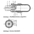
- the invention further relates to a burner for liquid fuels, with a central one Fuel lance, an air supply, which can be provided with a swirl device with an ignition device, with an optional flame tube, with an optional Heat exchanger for air preheating and with a porous body to stabilize one large or large-volume flame.
- the burner works in two operating states. State I, the start mode, serves that Preheat the burner to a minimum operating temperature. With the aim of minimizing the electrical Energy consumption - for example in the case of clocking small combustion systems - allows Construction and mode of operation according to the invention, however, also the heating by a Start burner operation.
- the burner works as a flame tube-stabilized burner inside the surrounding surface. This operating state only serves to heat the System to the minimum operating temperature of state II and is designed to be short in time.
- the construction according to the invention allows this burner to be used with little effort (Minimization of the necessary burner units and the electrical energy for Supply to the units).
- the smoke from the start burner in operating state I can pass directly through the porous one Body. This improves the heat transfer of the gases to the body to be heated, so that in comparison to a gas flow past Shortening the start phase can be achieved. A mechanical blockage of a the second routing of the flue gases from the start mode is also eliminated.
- the surface of the mixture can then be ignited conventionally by ignition electrodes become.
- the developed concept also allows for the outside Ignore ignition device and self-ignition of the mixture on the surface to effect. This works if the temperature of the surface is at least one point is high enough.
- the start burner allows the area around the end of the flame tube heated up sufficiently and made to glow easily. Through the relative large ignition area on the (partially or completely glowing) porous body the starting emissions of operating mode II of the combustion on the porous body in comparison for selective ignition sources (e.g. ignition electrodes) are kept low.
- the flue gases can be fed through openings in the area of the mixture formation.
- the dosage of the flue gases can be changed by changing the area of the opening Example by a slide or a plate also during operation.
- a Temperature control of the change in area can be done efficiently by temperature sensors or Bimetallic or fluidic.
- Flue gases can be drawn in through the impulse of the air in the start burner (short: primary air) become.
- the primary air can also be passed through heat exchangers (8) before entering the combustion chamber be preheated.
- a partial chemical conversion of the oil can be done through the choice of process parameters (Temperature, air volume, flue gas volume) can be reached.
- the space in the flame tube of the Startbrennner then acts as a pre-mixing and pre-reaction room.
- the Secondary air can also be preheated by heat exchangers (8) before mixing become.
- the impulse of the secondary air can overcome the pressure loss of the matrix of the surface burner can be used.
- the surface burner consists of a porous body (e.g. stainless steel, ceramic). This can be at the flue gas outlet behind the start burner or around it be attached around.
- a porous body e.g. stainless steel, ceramic
- the Surface burners can be cooled by the secondary air itself. Preheating the Secondary air then takes place partially or entirely in the surface burner.
- the surface burner can be used to influence the chemical conversion of the oil surface-enlarging substances and / or coated with catalytically active substances.
- the supply of the fuel to evaporate and heat the combustion air necessary energy can be done in different ways. One can be efficient Combination of the ways described.
- the air By heating the air to a temperature corresponding to the boiling point of the used fuel (with heating oil approx. 400 ° C) the back condensation of evaporated fuel avoided. If the air is heated further, the Energy requirements for the evaporation of the fuel from the air flow are met. The The fuel vapor is then expediently generated by direct injection of fuel in the hot air.
- the combustion air can be mixed with the Fuel mist can be heated.
- the heat exchanger can be in the form of tubes made by the air flows through, be arranged outside or inside the burner. By the arrangement within the burner can overheat the area of the fuel-air mixture can be avoided by heat dissipation.
- the heat exchanger is arranged outside the burner, it can also be used Low temperature heat (through flue gas cooling) in high temperature processes (chemistry, Stirling, u. a.) are coupled.
- flue gases are removed from the combustion at a high temperature level, it works above it the supply of part or all of the heat, which evaporates the fuel is required.
- the flue gases also cause an inertization of the Mixture formation zone and additional cooling of the flame zone.
- the heat is emitted by radiation through the very hot porous one in operating state II Body takes place both outside (to the medium to be heated, e.g. boiler water) as well also inside. This effect can be used to heat the premix zone if this lies within an area enclosed by the porous body.
- the Evaporation of the fuel then takes place not only through convective heat transfer hot air to the oil droplets, but also by the direct radiation on the individual Drops. Limiting the temperature in the premix zone can protect against Auto-ignition of the mixture through a layered construction of the porous body respectively.
- the outer layer of the surface is in support of the Combustion optimized (material, materials, structure).
- the inner layer is related to the exact coupling of the necessary heat optimized (heat conduction and Radiative properties).
Landscapes
- Engineering & Computer Science (AREA)
- Chemical & Material Sciences (AREA)
- Combustion & Propulsion (AREA)
- Mechanical Engineering (AREA)
- General Engineering & Computer Science (AREA)
- Spray-Type Burners (AREA)
- Nozzles For Spraying Of Liquid Fuel (AREA)
- Feeding And Controlling Fuel (AREA)
Claims (10)
- Procédé de combustion de combustibles liquides, dans lequel du combustible et de l'air sont mélangés par injection directe du combustible dans l'air, chauffés dans une zone de vaporisation et ensuite brûlés avec formation d'une flamme stable sur la surface d'un élément poreux (7) et dans lequel, dans une phase de démarrage, une flamme de démarrage est produite afin de fournir l'énergie de vaporisation dans la zone de vaporisation, laquelle flamme s'éteint après qu'une température de service minimale a été atteinte, caractérisé en ce qu'une partie au moins de l'apport de chaleur nécessaire à la vaporisation du combustible provient du recyclage du mélange d'air chaud et de vapeur de combustible dans la zone de vaporisation.
- Procédé selon la revendication 1, caractérisé en ce que l'apport de chaleur nécessaire à la vaporisation du combustible est obtenu par une ou plusieurs des mesures supplémentaires suivantes :a) couplage avec la chaleur de combustion par l'intermédiaire d'échangeurs de chaleur (8),b) couplage avec des gaz de combustion chauds, et/ouc) rayonnement thermique de surfaces chaudes.
- Procédé selon la revendication 1 ou la revendication 2, caractérisé en ce que le passage de la phase de démarrage au fonctionnement avec combustion superficielle lorsqu'une température de service minimale est atteinte se fait en interrompant le flux de combustible pendant une courte durée.
- Procédé selon l'une des revendications 1 à 3, caractérisé en ce que des gaz de combustion sont introduits dans la zone de vaporisation.
- Procédé selon l'une des revendications 1 à 4, caractérisé en ce qu'un flux d'air dans lequel l'air à mélanger avec le combustible est apporté est subdivisé enun flux d'air primaire qui est apporté par l'intermédiaire d'une buse d'air d'un brûleur de démarrage afin de produire 1a flamme de démarrage, etun flux d'air secondaire qui est amené au voisinage de l'élément poreux (7) ou dans celui-ci.
- Brûleur pour combustibles liquides, comprenant
une lance à combustible centrale (1),
une arrivée d'air (2),
une chambre de mélange pour mélanger le combustible injecté avec l'air injecté et pour vaporiser le combustible, et
un élément poreux (7) qui entoure une zone de vaporisation, délimite la chambre de mélange et forme un brûleur superficiel, un brûleur de démarrage étant disposé dans la chambre de mélange, lequel brûleur produit une flamme de démarrage dans une phase de démarrage et est ensuite utilisé pour la préparation du mélange de combustible et d'air,
caractérisé en ce qu'un tube à flamme (6) est agencé autour de la zone de vaporisation, l'élément poreux (7) dépassant dudit tube, et en ce qu'il est prévu une section de recyclage du mélange d'air chaud et de vapeur de combustible depuis l'élément poreux (7) jusqu'à la zone de vaporisation. - Brûleur selon la revendication 6, caractérisé en ce qu'il est prévu une section de transfert de chaleur radiante depuis l'élément poreux (7) vers la zone de vaporisation.
- Brûleur selon la revendication 6 ou la revendication 7, caractérisé en ce que le tube à flamme (6) présente des orifices de recyclage.
- Brûleur selon l'une des revendications 6 à 8, caractérisé en ce qu'il est prévu en plus, pour fournir l'énergie nécessaire à la vaporisation du combustible, un échangeur de chaleur (8) qui apporte dans la zone de vaporisation une partie de la chaleur dégagée lors de la combustion au moyen d'air chauffé.
- Brûleur selon l'une des revendications 6 à 9, caractérisé en ce que l'élément poreux (7) se présente sous la forme d'un élément poreux en nid d'abeilles dont les alvéoles sont traversées alternativement par de l'air et par du mélange combustible.
Applications Claiming Priority (5)
| Application Number | Priority Date | Filing Date | Title |
|---|---|---|---|
| DE19625217A DE19625217A1 (de) | 1996-06-25 | 1996-06-25 | Schadstoffarmer Oberflächenbrenner für flüssige Brennstoffe |
| DE19625217 | 1996-06-25 | ||
| DE19650973 | 1996-12-09 | ||
| DE19650973A DE19650973A1 (de) | 1996-12-09 | 1996-12-09 | Start- und Betriebsweise einer schadstoffarmen, an porösen Körpern stabilisierten Verbrennung flüssiger Brennstoffe |
| PCT/EP1997/003311 WO1997049952A1 (fr) | 1996-06-25 | 1997-06-24 | Procede et structure d'un bruleur pour la combustion superficielle pour combustibles liquides |
Publications (2)
| Publication Number | Publication Date |
|---|---|
| EP0906545A1 EP0906545A1 (fr) | 1999-04-07 |
| EP0906545B1 true EP0906545B1 (fr) | 2002-04-03 |
Family
ID=26026864
Family Applications (1)
| Application Number | Title | Priority Date | Filing Date |
|---|---|---|---|
| EP97929279A Expired - Lifetime EP0906545B1 (fr) | 1996-06-25 | 1997-06-24 | Bruleur pour la combustion superficielle de combustibles liquides et procede de combustion |
Country Status (4)
| Country | Link |
|---|---|
| EP (1) | EP0906545B1 (fr) |
| AT (1) | ATE215678T1 (fr) |
| DE (1) | DE59706874D1 (fr) |
| WO (1) | WO1997049952A1 (fr) |
Families Citing this family (5)
| Publication number | Priority date | Publication date | Assignee | Title |
|---|---|---|---|---|
| AT406414B8 (de) * | 1998-02-27 | 2000-07-25 | Windhager Zentralheizung Gmbh | Vorrichtung in mit flüssigen brennstoffen betriebenen heizungsanlagen |
| DE19821672A1 (de) * | 1998-05-14 | 1999-11-18 | Walter Swoboda | Vormischbrenner für flüssige Brennstoffe |
| EP1134496A1 (fr) * | 2000-03-15 | 2001-09-19 | Thermic Investments S.A. | Appareil de chauffage étanche à combustible liquide |
| DE102009043681B4 (de) * | 2009-10-01 | 2014-06-18 | Viessmann Werke Gmbh & Co Kg | Brenner für flüssigen Brennstoff |
| DE102010025107B4 (de) * | 2010-06-25 | 2012-08-09 | Robert Bosch Gmbh | Ölvormischbrenner |
Family Cites Families (8)
| Publication number | Priority date | Publication date | Assignee | Title |
|---|---|---|---|---|
| JPS5612908A (en) * | 1979-07-09 | 1981-02-07 | Kubota Ltd | Water heater |
| JPS5741508A (en) * | 1980-08-22 | 1982-03-08 | Toyo Fuitsuchingu Kk | Liquid fuel gasifying burner |
| US4865543A (en) * | 1984-08-30 | 1989-09-12 | Garbo Paul W | Liquid fuel combustion with porous fiber burner |
| US4643667A (en) * | 1985-11-21 | 1987-02-17 | Institute Of Gas Technology | Non-catalytic porous-phase combustor |
| DE3926699A1 (de) * | 1989-08-12 | 1991-02-14 | Kloeckner Waermetechnik | Gasbrenner |
| DE4317554C2 (de) * | 1993-05-26 | 1997-03-06 | Fraunhofer Ges Forschung | Warmwasserbereiter |
| DE19625217A1 (de) * | 1996-06-25 | 1996-11-28 | Heinrich Dr Ing Koehne | Schadstoffarmer Oberflächenbrenner für flüssige Brennstoffe |
| DE19650973A1 (de) * | 1996-12-09 | 1997-06-19 | Heinrich Dr Ing Koehne | Start- und Betriebsweise einer schadstoffarmen, an porösen Körpern stabilisierten Verbrennung flüssiger Brennstoffe |
-
1997
- 1997-06-24 AT AT97929279T patent/ATE215678T1/de not_active IP Right Cessation
- 1997-06-24 EP EP97929279A patent/EP0906545B1/fr not_active Expired - Lifetime
- 1997-06-24 WO PCT/EP1997/003311 patent/WO1997049952A1/fr not_active Ceased
- 1997-06-24 DE DE59706874T patent/DE59706874D1/de not_active Expired - Fee Related
Also Published As
| Publication number | Publication date |
|---|---|
| WO1997049952A1 (fr) | 1997-12-31 |
| EP0906545A1 (fr) | 1999-04-07 |
| DE59706874D1 (de) | 2002-05-08 |
| ATE215678T1 (de) | 2002-04-15 |
Similar Documents
| Publication | Publication Date | Title |
|---|---|---|
| DE19646957B4 (de) | Verfahren und Vorrichtung zur Verbrennung von Flüssigbrennstoff | |
| AT504398B1 (de) | Porenbrenner, sowie verfahren zum betrieb eines porenbrenners | |
| US20040058290A1 (en) | Self-sustaining premixed pilot burner for liquid fuels | |
| US8899969B2 (en) | Method and system for low-NOx dual-fuel combustion of liquid and/or gaseous fuels | |
| CH615262A5 (fr) | ||
| US4318689A (en) | Burner for liquid fuels | |
| ES2260452T3 (es) | Metodo y dispositivo para la combustion poco contaminante no catalitica de un combustible liquido. | |
| EP0927321B1 (fr) | Bruleur de prevaporisation et de premelange pour combustibles liquides | |
| DE4317554C2 (de) | Warmwasserbereiter | |
| EP1013995A2 (fr) | Procédé pour le traitement thermique de liquides non inflammables | |
| EP0906545B1 (fr) | Bruleur pour la combustion superficielle de combustibles liquides et procede de combustion | |
| DE4430267A1 (de) | Brenner zur flammenlosen Verbrennung eines Brenngas-Luftgemisches | |
| DE2323919C2 (de) | Verfahren zum Verbrennen von kohlenstoffhaltigen Brennstoffen zur Erzeugung von Energie in Form von Wärme | |
| DE10347509B4 (de) | Heizgerät mit einer Zerstäuberdüse | |
| EP0484777B1 (fr) | Procédé pour la stabilisation d'un processus de combustion | |
| DE19650973A1 (de) | Start- und Betriebsweise einer schadstoffarmen, an porösen Körpern stabilisierten Verbrennung flüssiger Brennstoffe | |
| WO1997049952A9 (fr) | Procede et structure d'un bruleur pour la combustion superficielle pour combustibles liquides | |
| RU81786U1 (ru) | Устройство для подачи топлива в топку | |
| DE102006060669B4 (de) | Katalytische Verdampfung von flüssigen Brennstoffen | |
| DE10042479C2 (de) | Vorrichtung und Verfahren zur katalytischen Oxidation von Brennstoffen | |
| WO1999060306A1 (fr) | Bruleur de premelange pour combustibles liquides | |
| EP0789188A2 (fr) | Brûleur catalytique | |
| JPH07158875A (ja) | ガス給湯器 | |
| JP3846998B2 (ja) | 燃料油と水の混合燃焼装置 | |
| DE19518787A1 (de) | Dampfbrenner für flüssige Brennstoffe in Wärmeerzeugern kleiner Leistung bei dem die Öldampferzeugung von der Verbrennung räumlich entkoppelt ist |
Legal Events
| Date | Code | Title | Description |
|---|---|---|---|
| PUAI | Public reference made under article 153(3) epc to a published international application that has entered the european phase |
Free format text: ORIGINAL CODE: 0009012 |
|
| 17P | Request for examination filed |
Effective date: 19990123 |
|
| AK | Designated contracting states |
Kind code of ref document: A1 Designated state(s): AT CH DE FR IT LI |
|
| 17Q | First examination report despatched |
Effective date: 20000404 |
|
| GRAG | Despatch of communication of intention to grant |
Free format text: ORIGINAL CODE: EPIDOS AGRA |
|
| RTI1 | Title (correction) |
Free format text: SURFACE-COMBUSTION LIQUID-FUEL BURNER AND METHOD OF COMBUSTION |
|
| RTI1 | Title (correction) |
Free format text: SURFACE-COMBUSTION LIQUID-FUEL BURNER AND METHOD OF COMBUSTION |
|
| GRAG | Despatch of communication of intention to grant |
Free format text: ORIGINAL CODE: EPIDOS AGRA |
|
| GRAH | Despatch of communication of intention to grant a patent |
Free format text: ORIGINAL CODE: EPIDOS IGRA |
|
| GRAH | Despatch of communication of intention to grant a patent |
Free format text: ORIGINAL CODE: EPIDOS IGRA |
|
| GRAA | (expected) grant |
Free format text: ORIGINAL CODE: 0009210 |
|
| AK | Designated contracting states |
Kind code of ref document: B1 Designated state(s): AT CH DE FR IT LI |
|
| PG25 | Lapsed in a contracting state [announced via postgrant information from national office to epo] |
Ref country code: IT Free format text: LAPSE BECAUSE OF FAILURE TO SUBMIT A TRANSLATION OF THE DESCRIPTION OR TO PAY THE FEE WITHIN THE PRE;WARNING: LAPSES OF ITALIAN PATENTS WITH EFFECTIVE DATE BEFORE 2007 MAY HAVE OCCURRED AT ANY TIME BEFORE 2007. THE CORRECT EFFECTIVE DATE MAY BE DIFFERENT FROM THE ONE RECORDED.SCRIBED TIME-LIMIT Effective date: 20020403 Ref country code: FR Free format text: LAPSE BECAUSE OF FAILURE TO SUBMIT A TRANSLATION OF THE DESCRIPTION OR TO PAY THE FEE WITHIN THE PRESCRIBED TIME-LIMIT Effective date: 20020403 |
|
| REF | Corresponds to: |
Ref document number: 215678 Country of ref document: AT Date of ref document: 20020415 Kind code of ref document: T |
|
| REG | Reference to a national code |
Ref country code: CH Ref legal event code: EP |
|
| REF | Corresponds to: |
Ref document number: 59706874 Country of ref document: DE Date of ref document: 20020508 |
|
| PG25 | Lapsed in a contracting state [announced via postgrant information from national office to epo] |
Ref country code: AT Free format text: LAPSE BECAUSE OF NON-PAYMENT OF DUE FEES Effective date: 20020624 |
|
| PG25 | Lapsed in a contracting state [announced via postgrant information from national office to epo] |
Ref country code: LI Free format text: LAPSE BECAUSE OF NON-PAYMENT OF DUE FEES Effective date: 20020630 Ref country code: CH Free format text: LAPSE BECAUSE OF NON-PAYMENT OF DUE FEES Effective date: 20020630 |
|
| EN | Fr: translation not filed | ||
| PLBE | No opposition filed within time limit |
Free format text: ORIGINAL CODE: 0009261 |
|
| STAA | Information on the status of an ep patent application or granted ep patent |
Free format text: STATUS: NO OPPOSITION FILED WITHIN TIME LIMIT |
|
| REG | Reference to a national code |
Ref country code: CH Ref legal event code: PL |
|
| 26N | No opposition filed |
Effective date: 20030106 |
|
| PGFP | Annual fee paid to national office [announced via postgrant information from national office to epo] |
Ref country code: DE Payment date: 20040802 Year of fee payment: 8 |
|
| PG25 | Lapsed in a contracting state [announced via postgrant information from national office to epo] |
Ref country code: DE Free format text: LAPSE BECAUSE OF NON-PAYMENT OF DUE FEES Effective date: 20060103 |