EP0906545B1 - Surface-combustion liquid-fuel burner and method of combustion - Google Patents
Surface-combustion liquid-fuel burner and method of combustion Download PDFInfo
- Publication number
- EP0906545B1 EP0906545B1 EP97929279A EP97929279A EP0906545B1 EP 0906545 B1 EP0906545 B1 EP 0906545B1 EP 97929279 A EP97929279 A EP 97929279A EP 97929279 A EP97929279 A EP 97929279A EP 0906545 B1 EP0906545 B1 EP 0906545B1
- Authority
- EP
- European Patent Office
- Prior art keywords
- fuel
- air
- burner
- porous body
- flame
- Prior art date
- Legal status (The legal status is an assumption and is not a legal conclusion. Google has not performed a legal analysis and makes no representation as to the accuracy of the status listed.)
- Expired - Lifetime
Links
Images
Classifications
-
- F—MECHANICAL ENGINEERING; LIGHTING; HEATING; WEAPONS; BLASTING
- F23—COMBUSTION APPARATUS; COMBUSTION PROCESSES
- F23D—BURNERS
- F23D11/00—Burners using a direct spraying action of liquid droplets or vaporised liquid into the combustion space
- F23D11/36—Details
- F23D11/40—Mixing tubes; Burner heads
-
- F—MECHANICAL ENGINEERING; LIGHTING; HEATING; WEAPONS; BLASTING
- F23—COMBUSTION APPARATUS; COMBUSTION PROCESSES
- F23D—BURNERS
- F23D11/00—Burners using a direct spraying action of liquid droplets or vaporised liquid into the combustion space
- F23D11/36—Details
- F23D11/42—Starting devices
-
- F—MECHANICAL ENGINEERING; LIGHTING; HEATING; WEAPONS; BLASTING
- F23—COMBUSTION APPARATUS; COMBUSTION PROCESSES
- F23D—BURNERS
- F23D14/00—Burners for combustion of a gas, e.g. of a gas stored under pressure as a liquid
- F23D14/12—Radiant burners
- F23D14/16—Radiant burners using permeable blocks
-
- F—MECHANICAL ENGINEERING; LIGHTING; HEATING; WEAPONS; BLASTING
- F23—COMBUSTION APPARATUS; COMBUSTION PROCESSES
- F23C—METHODS OR APPARATUS FOR COMBUSTION USING FLUID FUEL OR SOLID FUEL SUSPENDED IN A CARRIER GAS OR AIR
- F23C2900/00—Special features of, or arrangements for combustion apparatus using fluid fuels or solid fuels suspended in air; Combustion processes therefor
- F23C2900/99006—Arrangements for starting combustion
-
- F—MECHANICAL ENGINEERING; LIGHTING; HEATING; WEAPONS; BLASTING
- F23—COMBUSTION APPARATUS; COMBUSTION PROCESSES
- F23D—BURNERS
- F23D2207/00—Ignition devices associated with burner
Definitions
- the basis of the patent is a burner for liquid fuels (in the following example and called oil for short), with which the combustion with air stabilized on a porous surface the required concept for mixture preparation and the mode of operation of the Burner.
- the advantages of surface burning are based on the stabilization of the flame in close proximity to the surface or in the material used Surface structure.
- the structure of the porous surface offers the possibility of being catalytic bring effective substances into contact with combustion gases and thus direct influence to take on the reduction of pollutants in the reaction zone.
- the mixture In order to burn the surface, the mixture must form before the surface largely completed. While the mixture formation in gases is relatively easy is to be implemented, the premixing of liquid fuels requires a higher technical Expenditure. Aspects of segregation through condensation and agglomeration must be taken into account. The risk of self-ignition of the mixture below the Surface must be excluded.
- Heating phase which is necessary for the evaporation or evaporation of the fuel.
- Heating oil carry concepts for the evaporation or evaporation of liquid films, dic either run down hot surfaces or be sucked in by capillary forces, mostly on the problem of the formation of deposits on the surfaces of the evaporator.
- the deposits are reaction products from cracking reactions in the fuel oil occur at temperatures above 400 ° C.
- Such high temperatures up to above the Boiling end of the heating oil (380 to, 400 ° C) are for a sufficient heat transfer required from the evaporator wall to the liquid medium.
- the deposits lead to a deterioration in the heat transfer and thus the susceptibility to failure of the system.
- a burner for liquid fuels in which in the starting phase the fuel supplied is evaporated in an evaporation tube. This is done by an electric heater. The vaporized fuel is injected through injected into a mixing chamber. Pre-heated air is also introduced into this. The mixture from preheated fuel and preheated air burns during the start phase at the Surface of the porous body. After the start phase has ended, the power supply to the electric heater ended. The fuel is now evaporated by the heat of the combustion taking place on the porous body.
- a water heater is known from JP 56012908.
- the combustion takes place with this burner of liquid fuel by injecting the fuel directly into the air.
- the mixture is heated in an evaporation zone and then on the surface of a porous body burned.
- the application of the Evaporation energy in the evaporation zone through a spark plug a starting flame generated.
- the starting flame is extinguished after a minimum operating temperature has been reached. This is followed by the evaporation of the fuel on the surface of the porous body.
- the object of the invention is to improve such burners.
- the object is achieved by a method for combustion liquid fuels according to claim 1 or by a burner for liquid fuels according to claim 6.
- the mixture is prepared using the concept of Atomization and evaporation of the fuel in an air stream.
- the required system start-up capability (when the burner is cold started, it is available Mixture formation (evaporation) necessary thermal energy not yet available) is solved by the concept of combining a start burner (swirl-assisted flame tube stabilization) with a surface burner, and the Possibility of using the start burner units to process a fuel-air mixture to use for the surface burner.
- the required heat input takes place via various mechanisms, which in their Total ensure complete evaporation and overheating of the Avoid fuel mixture. This eliminates the risk of self-ignition of the mixture in the mixture formation zone avoided.
- the ignition temperature of the fuel for example Heating oil EL (220 ° C) occurs a spontaneous combustion of the fuel-air mixture under the Conditions in this burner concept only at much higher temperatures (> 500 ° C) on. Only then can the homogeneous mixture formation (complete evaporation and over-stoichiometric mixture with atmospheric oxygen) can be achieved.
- the contact of the liquid fuel be avoided with hot walls. This applies both to the mixture formation process as well as for the transport of the mixture to the surface of the burner.
- the glowing Surface for flame stabilization is not a critical zone, as this is due to its high temperature is not wetted. Deposits that may have formed at the start can be are even burned off here without residue.
- the invention further relates to a burner for liquid fuels, with a central one Fuel lance, an air supply, which can be provided with a swirl device with an ignition device, with an optional flame tube, with an optional Heat exchanger for air preheating and with a porous body to stabilize one large or large-volume flame.
- the burner works in two operating states. State I, the start mode, serves that Preheat the burner to a minimum operating temperature. With the aim of minimizing the electrical Energy consumption - for example in the case of clocking small combustion systems - allows Construction and mode of operation according to the invention, however, also the heating by a Start burner operation.
- the burner works as a flame tube-stabilized burner inside the surrounding surface. This operating state only serves to heat the System to the minimum operating temperature of state II and is designed to be short in time.
- the construction according to the invention allows this burner to be used with little effort (Minimization of the necessary burner units and the electrical energy for Supply to the units).
- the smoke from the start burner in operating state I can pass directly through the porous one Body. This improves the heat transfer of the gases to the body to be heated, so that in comparison to a gas flow past Shortening the start phase can be achieved. A mechanical blockage of a the second routing of the flue gases from the start mode is also eliminated.
- the surface of the mixture can then be ignited conventionally by ignition electrodes become.
- the developed concept also allows for the outside Ignore ignition device and self-ignition of the mixture on the surface to effect. This works if the temperature of the surface is at least one point is high enough.
- the start burner allows the area around the end of the flame tube heated up sufficiently and made to glow easily. Through the relative large ignition area on the (partially or completely glowing) porous body the starting emissions of operating mode II of the combustion on the porous body in comparison for selective ignition sources (e.g. ignition electrodes) are kept low.
- the flue gases can be fed through openings in the area of the mixture formation.
- the dosage of the flue gases can be changed by changing the area of the opening Example by a slide or a plate also during operation.
- a Temperature control of the change in area can be done efficiently by temperature sensors or Bimetallic or fluidic.
- Flue gases can be drawn in through the impulse of the air in the start burner (short: primary air) become.
- the primary air can also be passed through heat exchangers (8) before entering the combustion chamber be preheated.
- a partial chemical conversion of the oil can be done through the choice of process parameters (Temperature, air volume, flue gas volume) can be reached.
- the space in the flame tube of the Startbrennner then acts as a pre-mixing and pre-reaction room.
- the Secondary air can also be preheated by heat exchangers (8) before mixing become.
- the impulse of the secondary air can overcome the pressure loss of the matrix of the surface burner can be used.
- the surface burner consists of a porous body (e.g. stainless steel, ceramic). This can be at the flue gas outlet behind the start burner or around it be attached around.
- a porous body e.g. stainless steel, ceramic
- the Surface burners can be cooled by the secondary air itself. Preheating the Secondary air then takes place partially or entirely in the surface burner.
- the surface burner can be used to influence the chemical conversion of the oil surface-enlarging substances and / or coated with catalytically active substances.
- the supply of the fuel to evaporate and heat the combustion air necessary energy can be done in different ways. One can be efficient Combination of the ways described.
- the air By heating the air to a temperature corresponding to the boiling point of the used fuel (with heating oil approx. 400 ° C) the back condensation of evaporated fuel avoided. If the air is heated further, the Energy requirements for the evaporation of the fuel from the air flow are met. The The fuel vapor is then expediently generated by direct injection of fuel in the hot air.
- the combustion air can be mixed with the Fuel mist can be heated.
- the heat exchanger can be in the form of tubes made by the air flows through, be arranged outside or inside the burner. By the arrangement within the burner can overheat the area of the fuel-air mixture can be avoided by heat dissipation.
- the heat exchanger is arranged outside the burner, it can also be used Low temperature heat (through flue gas cooling) in high temperature processes (chemistry, Stirling, u. a.) are coupled.
- flue gases are removed from the combustion at a high temperature level, it works above it the supply of part or all of the heat, which evaporates the fuel is required.
- the flue gases also cause an inertization of the Mixture formation zone and additional cooling of the flame zone.
- the heat is emitted by radiation through the very hot porous one in operating state II Body takes place both outside (to the medium to be heated, e.g. boiler water) as well also inside. This effect can be used to heat the premix zone if this lies within an area enclosed by the porous body.
- the Evaporation of the fuel then takes place not only through convective heat transfer hot air to the oil droplets, but also by the direct radiation on the individual Drops. Limiting the temperature in the premix zone can protect against Auto-ignition of the mixture through a layered construction of the porous body respectively.
- the outer layer of the surface is in support of the Combustion optimized (material, materials, structure).
- the inner layer is related to the exact coupling of the necessary heat optimized (heat conduction and Radiative properties).
Landscapes
- Engineering & Computer Science (AREA)
- Chemical & Material Sciences (AREA)
- Combustion & Propulsion (AREA)
- Mechanical Engineering (AREA)
- General Engineering & Computer Science (AREA)
- Spray-Type Burners (AREA)
- Nozzles For Spraying Of Liquid Fuel (AREA)
- Feeding And Controlling Fuel (AREA)
Abstract
Description
Grundlage des Patents ist ein Brenner für flüssige Brennstoffe (im folgenden beispielhaft und kurz Öl genannt), mit dem die Verbrennung mit Luft an einer porösen Oberfläche stabilisiert wird, das erforderliche Konzept zur Gemischaufbereitung sowie die Betriebsweise des Brenners.The basis of the patent is a burner for liquid fuels (in the following example and called oil for short), with which the combustion with air stabilized on a porous surface the required concept for mixture preparation and the mode of operation of the Burner.
Die Technik der Oberflächenverbrennung ist aus der Verbrennung von Gasen bekannt und wird dort bereits für Strahlungsbrenner zum Beispiel zur Beheizung von Industriehallen und zur Gebäudebeheizung (Gas-Wandthermen) eingesetzt.The technique of surface combustion is known from the combustion of gases and is already there for radiant burners, for example for heating industrial halls and used for heating buildings (gas wall heaters).
Die Vorteile der Oberflächenverbrennung basieren auf der Stabilisierung der Flamme in direkter Nähe der Oberfläche beziehungsweise im Material der verwendeten Oberflächenstruktur. Der Festkörper heizt sich durch die Nähe der Flamme stark auf und kann einen großen Teil der Reaktionswärme durch Wärmestrahlung an die Umgebung abgeben. Damit wird eine effektive Art der Flammenkühlung und dadurch eine Absenkung der thermischen Stickoxidbildung erreicht. Da die Wärmeübertragung zu einem großen Teil durch Wärmestrahlung erfolgt, kann der Wärmetauscher sehr kompakt ausgeführt werden. Aufgrund der niedrigen Geschwindigkeit der Gase an der Oberfläche und der damit verbundenen geringen Turbulenzen werden Flammengeräusche weitgehend vermieden.The advantages of surface burning are based on the stabilization of the flame in close proximity to the surface or in the material used Surface structure. The solid heats up strongly due to the proximity of the flame and can emit a large part of the heat of reaction to the environment through heat radiation. This will be an effective way of flame cooling and thereby lowering the thermal nitrogen oxide formation reached. Because the heat transfer through to a large extent Heat radiation occurs, the heat exchanger can be made very compact. by virtue of the low velocity of the gases on the surface and the associated low turbulence, flame noises are largely avoided.
Darüber hinaus bietet die Struktur der porösen Oberfläche die Möglichkeit, katalytisch wirksame Stoffe in den Kontakt mit Verbrennungsgasen zu bringen und so direkten Einfluß auf die Reduzierung von Schadstoffen in der Reaktionszone zu nehmen. In addition, the structure of the porous surface offers the possibility of being catalytic bring effective substances into contact with combustion gases and thus direct influence to take on the reduction of pollutants in the reaction zone.
Für die Oberflächenverbrennung muß die Gemischbildung bereits vor der Oberfläche weitgehend abgeschlossen sein. Während die Gemischbildung bei Gasen relativ einfach umzusetzen ist, erfordert die Vormischung flüssiger Brennstoffe einen höheren technischen Aufwand. Aspekte der Entmischung durch Kondensation und Agglomeration müssen berücksichtigt werden. Die Gefahr einer Selbstzündung des Gemisches unterhalb der Oberfläche muß ausgeschlossen werden.In order to burn the surface, the mixture must form before the surface largely completed. While the mixture formation in gases is relatively easy is to be implemented, the premixing of liquid fuels requires a higher technical Expenditure. Aspects of segregation through condensation and agglomeration must be taken into account. The risk of self-ignition of the mixture below the Surface must be excluded.
Das Problem der homogenen Gemischbildung bei flüssigen Brennstoffen besteht in der Aufheizphase, die zur Verdunstung oder Verdampfung des Brennstoffs notwendig ist. Bei Heizöl führen Konzepte zur Verdampfung oder Verdunstung von Flüssigkeitsfilmen, dic entweder an heißen Oberflächen herablaufen oder durch kapillare Kräfte angesaugt werden, meist zu dem Problem der Bildung von Ablagerungen an den Oberflächen des Verdampfers. Die Ablagerungen sind Reaktionsprodukte aus Crackreaktionen im Brennstoff Heizöl die bei Temperaturen oberhalb von 400 °C auftreten. Solch hohe Temperaturen bis oberhalb des Siedeendes des Heizöls (380 bis, 400 °C) sind aber für einen ausreichenden Wärmeübergang von der Verdampferwand an das flüssige Medium erforderlich. Die Ablagerungen führen zu einer Verschlechterung des Wärmeübergangs und damit zur Störanfälligkeit des Systems.The problem of homogeneous mixture formation in liquid fuels is that Heating phase, which is necessary for the evaporation or evaporation of the fuel. at Heating oil carry concepts for the evaporation or evaporation of liquid films, dic either run down hot surfaces or be sucked in by capillary forces, mostly on the problem of the formation of deposits on the surfaces of the evaporator. The deposits are reaction products from cracking reactions in the fuel oil occur at temperatures above 400 ° C. Such high temperatures up to above the Boiling end of the heating oil (380 to, 400 ° C) are for a sufficient heat transfer required from the evaporator wall to the liquid medium. The deposits lead to a deterioration in the heat transfer and thus the susceptibility to failure of the system.
Aus JP 57041508 ist ein Brenner für flüssige Brennstoffe bekannt, bei dem in der Startphase der zugeführte Brennstoff in einem Verdampfungsrohr verdampft wird. Dies erfolgt durch eine elektrische Heizvorrichtung. Der verdampfte Brennstoff wird durch Injektionsdüsen in eine Mischkammer injiziert. In diese wird ferner vorgeheizte Luft eingeführt. Das Gemisch aus vorgeheiztem Brennstoff und vorgeheizter Luft verbrennt während der Startphase an der Oberfläche des porösen Körpers. Nach Beendigen der Startphase wird die Stomzufuhr der elektrischen Heizvorrichtung beendet. Die Verdampfung des Brennstoffs erfolgt nunmehr durch die Wärme der an dem porösen Körper erfolgenden Verbrennung.From JP 57041508 a burner for liquid fuels is known, in which in the starting phase the fuel supplied is evaporated in an evaporation tube. This is done by an electric heater. The vaporized fuel is injected through injected into a mixing chamber. Pre-heated air is also introduced into this. The mixture from preheated fuel and preheated air burns during the start phase at the Surface of the porous body. After the start phase has ended, the power supply to the electric heater ended. The fuel is now evaporated by the heat of the combustion taking place on the porous body.
Aus JP 56012908 ist ein Wassererhitzer bekannt. Bei diesem Brenner erfolgt die Verbrennung von flüssigem Brennstoff durch direktes Eindüsen des Brennstoffs in die Luft. Das Gemisch wird in einer Verdampfungszone aufgeheizt und anschließend an der Oberfläche eines porösen Körpers verbrannt. In einer Startphase wird zum Aufbringen der Verdampfungsenergie in der Verdampfungszone durch eine Zündkerze eine Startflamme erzeugt. Die Startflamme wird nach Erreichen einer Mindestbetriebs-Temperatur gelöscht. Hierauf folgt das Verdampfen des Brennstoffs an der Oberfläche des porösen Körpers.A water heater is known from JP 56012908. The combustion takes place with this burner of liquid fuel by injecting the fuel directly into the air. The mixture is heated in an evaporation zone and then on the surface of a porous body burned. In a starting phase, the application of the Evaporation energy in the evaporation zone through a spark plug a starting flame generated. The starting flame is extinguished after a minimum operating temperature has been reached. This is followed by the evaporation of the fuel on the surface of the porous body.
Aufgabe der Erfindung ist es, derartige Brenner zu verbessern.The object of the invention is to improve such burners.
Die Lösung der Aufgabe erfolgt erfindungsgemäß durch ein Verfahren zur Verbrennung
flüssiger Brennstoffe gemäß Anspruch 1 bzw. durch einen Brenner für flüssige Brennstoffe
gemäß Anspruch 6.According to the invention, the object is achieved by a method for combustion
liquid fuels according to
Die Gemischaufbereitung erfolgt durch das Konzept der Zerstäubung und Verdunstung des Brennstoffs in einen Luftstrom. Die erforderliche Startfähigkeit des Systems (beim Kaltstart des Brenners steht die zur Gemischbildung (Verdunstung) notwendige thermische Energie noch nicht zur Verfügung) wird gelöst durch das Konzept der Kombination eines Startbrenners (drallunterstützte Flammenrohrstabilisierung) mit einem Oberflächenbrenner, und der Möglichkeit, die Aggregate des Startbrenners zur Aufbereitung eines Brennstoff-Luftgemischs für den Oberflächenbrenner zu nutzen.The mixture is prepared using the concept of Atomization and evaporation of the fuel in an air stream. The required system start-up capability (when the burner is cold started, it is available Mixture formation (evaporation) necessary thermal energy not yet available) is solved by the concept of combining a start burner (swirl-assisted flame tube stabilization) with a surface burner, and the Possibility of using the start burner units to process a fuel-air mixture to use for the surface burner.
Die erforderliche Wärmeeinkopplung erfolgt über verschiedene Mechanismen, die in ihrer Summe die vollständige Verdunstung gewährleisten und eine Überhitzung des Brennstoffgemischs vermeiden. Dadurch wird die Gefahr der Selbstzündung des Gemischs in der Gemischbildungszone vermieden. Im Gegensatz zum bisherigen Stand des Wissens der Zündtemperatur zum Beispiel des Brennstoffs Heizöl EL (220 °C) tritt eine Selbstentzündung des Brennstoff-Luft-Gemisches unter den Bedingungen in diesem Brennerkonzept erst bei sehr viel höheren Temperaturen (>500 °C) auf. Erst dadurch kann die homogene Gemischbildung (vollständige Verdampfung und überstöchiometrische Mischung mit Luftsauerstoff) erreicht werden.The required heat input takes place via various mechanisms, which in their Total ensure complete evaporation and overheating of the Avoid fuel mixture. This eliminates the risk of self-ignition of the mixture in the mixture formation zone avoided. In contrast to the previous state of knowledge the ignition temperature of the fuel, for example Heating oil EL (220 ° C) occurs a spontaneous combustion of the fuel-air mixture under the Conditions in this burner concept only at much higher temperatures (> 500 ° C) on. Only then can the homogeneous mixture formation (complete evaporation and over-stoichiometric mixture with atmospheric oxygen) can be achieved.
Zur Vermeidung der Bildung von Ablagerungen muß der Kontakt des flüssigen Brennstoffs mit heißen Wänden vermieden werden. Dies gilt sowohl für den Prozeß der Gemischbildung als auch für den Transport des Gemisches zur Oberfläche des Brenners. Die glühende Oberfläche zur Flammenstabilisierung stellt keine kritische Zone dar, da diese aufgrund ihrer hohen Temperatur nicht benetzt wird. Eventuell beim Start gebildete Ablagerungen können hier sogar rückstandsfrei abgebrannt werden.To avoid the formation of deposits, the contact of the liquid fuel be avoided with hot walls. This applies both to the mixture formation process as well as for the transport of the mixture to the surface of the burner. The glowing Surface for flame stabilization is not a critical zone, as this is due to its high temperature is not wetted. Deposits that may have formed at the start can be are even burned off here without residue.
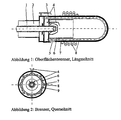
Gegenstand der Erfindung ist ferner ein Brenner für flüssige Brennstoffe, mit einer zentralen Brennstofflanze, einer Luftzuführung, die mit einer Dralleinrichtung versehen sein kann, mit einer Zündvorrichtung, mit einem optionalen Flammenrohr, mit einem optionalen Wärmetauscher zur Luftvorwärmung und mit einem porösen Körper zur Stabilisierung einer großflächigen bzw. großvolumigen Flamme.The invention further relates to a burner for liquid fuels, with a central one Fuel lance, an air supply, which can be provided with a swirl device with an ignition device, with an optional flame tube, with an optional Heat exchanger for air preheating and with a porous body to stabilize one large or large-volume flame.
Der Brenner arbeitet in zwei Betriebszuständen. Der Zustand I, der Startmodus, dient dem Vorheizen des Brenners auf eine Mindestbetriebstemperatur. Mit der Zielsetzung einer möglichst geringen elektrischen Energieaufnahme - zum Beispiel bei taktenden Kleinfeuerungsanlagen - gestattet die erfindungsgemäße Konstruktion und Betriebsweise jedoch auch die Aufheizung durch einen Start-Brennerbetrieb. Der Brenner arbeitet als Flammenrohr-stabilisierter Brenner im Inneren der umschließenden Oberfläche. Dieser Betriebszustand dient nur zur Aufheizung des Systems auf die Mindest-Betriebstemperatur des Zustands II und ist zeitlich kurz ausgelegt. Die erfindungsgemäße Konstruktion gestattet es, diesen Brenner mit geringem Aufwand (Minimierung der notwendigen Brenneraggregate sowie der elektrischen Energie zur Versorgung der Aggregate) zu betreiben.The burner works in two operating states. State I, the start mode, serves that Preheat the burner to a minimum operating temperature. With the aim of minimizing the electrical Energy consumption - for example in the case of clocking small combustion systems - allows Construction and mode of operation according to the invention, however, also the heating by a Start burner operation. The burner works as a flame tube-stabilized burner inside the surrounding surface. This operating state only serves to heat the System to the minimum operating temperature of state II and is designed to be short in time. The construction according to the invention allows this burner to be used with little effort (Minimization of the necessary burner units and the electrical energy for Supply to the units).
Die Rauchgase des Startbrenners im Betriebszustand I können direkt durch den porösen Körper geleitet werden. Dadurch verbessert sich der Wärmeübergang der Gase an den aufzuheizenden Körper, so daß im Vergleich zu einer Vorbeiströmung der Gase eine Verkürzung der Startphase erreicht werden kann. Eine mechanische Versperrung einer zweiten Wegführung der Rauchgase des Startbetriebes entfällt damit ebenfalls.The smoke from the start burner in operating state I can pass directly through the porous one Body. This improves the heat transfer of the gases to the body to be heated, so that in comparison to a gas flow past Shortening the start phase can be achieved. A mechanical blockage of a the second routing of the flue gases from the start mode is also eliminated.
Zum Abbruch des Betriebszustands I (Startbetrieb) genügt es, die stabile Verbrennung des Brennstoffnebel-Luftgemischs kurzfristig zu unterbrechen. Dies geschieht zweckmäßig durch eine sehr kurze Unterbrechung der Ölzufuhr. Nach dem Verlöschen der Flamme kann sich bei erneuter Ölzufuhr keine neue Flammenzone ausbilden, wenn die Zündvorrichtung im Inneren des Brenners nicht aktiviert wird. Im Bereich des Flammenrohres wird dann ein Öldampf-Luftgemisch erzeugt, das dem Bereich des porösen Körpers zugeführt werden kann.To abort operating state I (start operation), it is sufficient to have the combustion of the Interrupt fuel-air mixture for a short time. This is conveniently done through a very short interruption in the oil supply. After the flame has extinguished, the Do not create a new flame zone if the igniter is inside the burner is not activated. An oil vapor-air mixture is then in the area of the flame tube generated that can be supplied to the area of the porous body.
Das Gemisch kann an der Oberfläche dann konventionell durch Zündelektroden entzündet werden. Das entwickelte Konzept gestattet es jedoch auch, auf die außen liegende Zündeinrichtung zu verzichten und eine Selbst-Entzündung des Gemisches an der Oberfläche zu bewirken. Dies gelingt, wenn die Temperatur der Oberfläche an mindestens einer Stelle genügend hoch liegt. Durch den Startbrenner kann der Bereich um das Flammenrohrende genügend stark aufgeheizt und leicht zum Glühen gebracht werden. Durch den relativ großflächigen Zündbereich an dem (teilweise oder ganz glühenden) porösen Körper können die Startemissionen des Betriebsmodus II der Verbrennung am porösen Körper im Vergleich zu punktuellen Zündquellen (z. B. Zündelektroden) niedrig gehalten werden.The surface of the mixture can then be ignited conventionally by ignition electrodes become. However, the developed concept also allows for the outside Ignore ignition device and self-ignition of the mixture on the surface to effect. This works if the temperature of the surface is at least one point is high enough. The start burner allows the area around the end of the flame tube heated up sufficiently and made to glow easily. Through the relative large ignition area on the (partially or completely glowing) porous body the starting emissions of operating mode II of the combustion on the porous body in comparison for selective ignition sources (e.g. ignition electrodes) are kept low.
Durch eine geeignete Strömungsführung (Ziel einer schnellen Homogenisierung des Gemisches) und Begrenzung der Temperatur (insbesondere der Wärmeeinstrahlung durch die glühende Oberfläche) kann die Selbstentzündung des zündfähigen Öldampf-Luft-Gemisches innerhalb des Brenners vermieden werden. Bei Einsatz des Brenners in Prozessen, die eine hohe Luftvorwärmung durch eine notwendige Abgaskühlung beinhalten (chemische Hochtemperaturprozesse, Stirlingmotor, u. a.), oder bei anderen erforderlichen Randbedingungen kann die Selbstzündung auch durch die Einkopplung von Rauchgasen in die Gemischbildungszone und / oder durch die Teilung des Luftstroms in einen Primär- und einen Sekundärluftstrom vermieden werden. Beide Methoden bewirken eine Inertisierung des Gemisches (Reduzierung des Sauerstoffpartialdrucks) und damit eine erhöhte Zündverzögerung. Through a suitable flow control (aim of a quick homogenization of the Mixture) and limitation of the temperature (in particular the heat radiation by the glowing surface) can self-ignite the ignitable oil vapor-air mixture be avoided within the burner. When using the burner in processes that have a include high air preheating due to necessary exhaust gas cooling (chemical High temperature processes, Stirling engine, u. a.), or other required Boundary conditions can also be achieved by coupling flue gases into the mixture formation zone and / or by dividing the air flow into a primary and a secondary air flow can be avoided. Both methods cause the Mixture (reduction of the oxygen partial pressure) and thus an increased Ignition delay.
Die Rauchgase können über Öffnungen im Bereich der Gemischbildung zugeführt werden. Die Dosierung der Rauchgase kann über die Veränderung der Fläche der Öffnung zum Beispiel durch einen Schieber oder eine Platte auch während des Betriebs erfolgen. Eine Temperatursteuerung der Veränderung der Fläche kann effizient durch Temperaturfühler oder Bimetalle oder auch strömungstechnisch erfolgen.The flue gases can be fed through openings in the area of the mixture formation. The dosage of the flue gases can be changed by changing the area of the opening Example by a slide or a plate also during operation. A Temperature control of the change in area can be done efficiently by temperature sensors or Bimetallic or fluidic.
Rauchgase können durch den Impuls der Luft im Startbrenner (kurz: Primärluft) angesaugt werden. Die Primärluft kann auch durch Wärmetauscher (8) vor Eintritt in die Brennkammer vorgeheizt werden. Durch das Einbringen des Öls in das heiße Rauchgas-Primärluft-Gemisch erfolgt eine schnelle Verdunstung des Öls sowie eine homogene Vermischung.Flue gases can be drawn in through the impulse of the air in the start burner (short: primary air) become. The primary air can also be passed through heat exchangers (8) before entering the combustion chamber be preheated. By introducing the oil into the hot flue gas / primary air mixture the oil evaporates quickly and mixes homogeneously.
Eine partielle chemische Umsetzung des Öls kann durch die Wahl der Prozeßparameter (Temperatur, Luftmenge, Rauchgasmenge) erreicht werden. Der Raum im Flammenrohr des Startbrennners fungiert dann als Vormisch- sowie Vorreaktionsraum.A partial chemical conversion of the oil can be done through the choice of process parameters (Temperature, air volume, flue gas volume) can be reached. The space in the flame tube of the Startbrennner then acts as a pre-mixing and pre-reaction room.
Bei einer Teilung des Luftstroms (zwecks Inertisierung der Gemischbildungszone) erfolgt die Zumischung weiterer Luft (kurz: Sekundärluft) stromabwärts des Flammenrohrs. Die Sekundärluft kann ebenfalls durch Wärmetauscher (8) vor der Zumischung vorgeheizt werden. Der Impuls der Sekundärluft kann zur Überwindung des Druckverlustes der Matrix des Oberflächenbrenners genutzt werden.If the air flow is divided (for the purpose of inerting the mixture formation zone), this takes place Addition of additional air (short: secondary air) downstream of the flame tube. The Secondary air can also be preheated by heat exchangers (8) before mixing become. The impulse of the secondary air can overcome the pressure loss of the matrix of the surface burner can be used.
Der Oberflächenbrenner besteht aus einem porösen Körper (z. B. Edelstahl, Keramik). Dieser kann an der Rauchgasaustrittsöffnung hinter dem Startbrenner oder zylindrisch um diesen herum angebracht sein.The surface burner consists of a porous body (e.g. stainless steel, ceramic). This can be at the flue gas outlet behind the start burner or around it be attached around.
Um eine Rückzündung des Brennstoffgemischs in den Bereich der Sekundärluftzumischung (vor den Oberflächenbrenner) durch die heiße Oberfläche zu vermeiden, kann der Oberflächenbrenner durch die Sekundärluft selbst gekühlt werden. Die Vorwärmung der Sekundärluft erfolgt dann teilweise oder ganz im Oberflächenbrenner.To re-ignite the fuel mixture in the area of the secondary air admixture (in front of the surface burner) through the hot surface, the Surface burners can be cooled by the secondary air itself. Preheating the Secondary air then takes place partially or entirely in the surface burner.
Eine besonders gleichmäßige Zumischung der Sekundärluft ohne Gefahr einer vorzeitigen Zündung des Gemisches ist durch die Mischung in der Oberflächenmatrix selbst möglich. A particularly even addition of secondary air without the risk of premature Ignition of the mixture is possible through the mixture in the surface matrix itself.
Der Oberflächenbrenner kann zur Beeinflussung der chemischen Umsetzung des Öls mit oberflächenvergrößemden Stoffen und/oder mit katalytisch aktiven Stoffen beschichtet sein.The surface burner can be used to influence the chemical conversion of the oil surface-enlarging substances and / or coated with catalytically active substances.
Die Zufuhr der zur Verdunstung des Brennstoffs und zur Aufheizung der Verbrennungsluft notwendigen Energie kann auf verschiedenen Wegen erfolgen. Effizient kann eine Kombination der beschriebenen Wege sein.The supply of the fuel to evaporate and heat the combustion air necessary energy can be done in different ways. One can be efficient Combination of the ways described.
Durch die Aufheizung der Luft auf eine Temperatur entsprechend dem Siedeende des verwendeten Brennstoffs (bei Heizöl ca. 400°C) wird die Rückkondensation von verdunstetem Brennstoff vermieden. Bei einer weiteren Aufheizung der Luft kann der Energiebedarf zur Verdunstung des Brennstoffs aus dem Luftstrom gedeckt werden. Die Erzeugung des Brennstoffdampfes erfolgt dann zweckmäßig durch die direkte Einspritzung des Brennstoffs in die heiße Luft.By heating the air to a temperature corresponding to the boiling point of the used fuel (with heating oil approx. 400 ° C) the back condensation of evaporated fuel avoided. If the air is heated further, the Energy requirements for the evaporation of the fuel from the air flow are met. The The fuel vapor is then expediently generated by direct injection of fuel in the hot air.
Durch einen Wärmetauscher kann die Verbrennungsluft vor der Mischung mit dem Brennstoffnebel aufgeheizt werden. Der Wärmetauscher kann in Form von Rohren, die von der Luft durchströmt werden, außerhalb oder innerhalb des Brenners angeordnet sein. Durch die Anordnung innerhalb des Brenners kann eine Überhitzung des Bereichs der Brennstoff-Luft-Mischung durch Wärmeabfuhr vermieden werden.By means of a heat exchanger, the combustion air can be mixed with the Fuel mist can be heated. The heat exchanger can be in the form of tubes made by the air flows through, be arranged outside or inside the burner. By the arrangement within the burner can overheat the area of the fuel-air mixture can be avoided by heat dissipation.
Wird der Wärmetauscher außerhalb des Brenners angeordnet, kann damit auch Niedertemperaturwärme (durch Rauchgaskühlung) in Hochtemperaturprozesse (Chemie, Stirling, u. a.) eingekoppelt werden. If the heat exchanger is arranged outside the burner, it can also be used Low temperature heat (through flue gas cooling) in high temperature processes (chemistry, Stirling, u. a.) are coupled.
Wenn Rauchgase der Verbrennung auf hohem Temperaturniveau entnommen werden, gelingt darüber die Zufuhr eines Teil oder der gesamten Wärme, die zur Verdunstung des Brennstoffs erforderlich ist. Die Rauchgase bewirken darüber hinaus eine Inertisierung der Gemischbildungszone sowie eine zusätzliche Kühlung der Flammenzone.If flue gases are removed from the combustion at a high temperature level, it works above it the supply of part or all of the heat, which evaporates the fuel is required. The flue gases also cause an inertization of the Mixture formation zone and additional cooling of the flame zone.
Die Abgabe der Wärme durch Strahlung durch den im Betriebszustand II sehr heißen porösen Körper erfolgt sowohl nach außen (an das zu beheizende Medium, z.B. Kesselwasser) als auch nach innen. Dieser Effekt kann zur Beheizung der Vormischzone genutzt werden, wenn diese innerhalb eines von dem porösen Körper umschlossenen Bereichs liegt. Die Verdunstung des Brennstoffs erfolgt dann nicht nur durch konvektiven Wärmetransport der heißen Luft an die Öltröpfchen, sondern auch durch die direkte Einstrahlung auf die einzelnen Tropfen. Die Begrenzung der Temperatur in der Vormischzone kann zum Schutz vor Selbstentzündung des Gemisches durch eine geschichtete Bauweise des porösen Körpers erfolgen. Die äußere Schicht der Oberfläche wird in Bezug auf die Unterstützung der Verbrennung optimiert (Material, Werkstoffe, Struktur). Die innere Schicht wird in Bezug auf die genaue Einkopplung der notwendigen Wärme optimiert (Wärmeleitungs- und Strahlungseigenschaften).The heat is emitted by radiation through the very hot porous one in operating state II Body takes place both outside (to the medium to be heated, e.g. boiler water) as well also inside. This effect can be used to heat the premix zone if this lies within an area enclosed by the porous body. The Evaporation of the fuel then takes place not only through convective heat transfer hot air to the oil droplets, but also by the direct radiation on the individual Drops. Limiting the temperature in the premix zone can protect against Auto-ignition of the mixture through a layered construction of the porous body respectively. The outer layer of the surface is in support of the Combustion optimized (material, materials, structure). The inner layer is related to the exact coupling of the necessary heat optimized (heat conduction and Radiative properties).
Durch die Einsaugung von überhitztem Öldampf-Luft-Gemisch in den Bereich der Brennstoff- und Luftzufuhr kann Wärme zur Verdunstung in die Vormischzone eingetragen werden. Bei der Beaufschlagung des porösen Körpers mit dem Öldampf kommt es durch die Strahlung des Körpers nach innen zu einer weiteren Erwärmung des Gemisches. Ein Teil des Gemischstromes kann durch den Unterdruck der Luftzuführung in den Bereich der Vormischkammer zurückgesaugt werden. Dies erfolgt nach dem gleichen Prinzip wie die Einsaugung von Rauchgasen zur Flammenkühlung bei herkömmlichen Brennern. Wird das Flammenrohr für den Brenner im Betriebszustand I mit Rezirkulationsöffnungen betrieben, so erfolgt die Rücksaugung von überhitztem Öldampf automatisch durch diese Öffnungen.By sucking in superheated oil vapor-air mixture in the area of Fuel and air supply can enter heat for evaporation in the premix zone become. When the oil vapor is applied to the porous body, it comes through Radiation of the body inwards to further warm the mixture. Part of the Mixture flow can be caused by the negative pressure of the air supply in the area Premixing chamber are sucked back. This is done on the same principle as that Intake of smoke gases for flame cooling in conventional burners. Will that Flame tube for the burner in operating state I operated with recirculation openings, see above Superheated oil vapor is automatically sucked back through these openings.
Claims (10)
- Method for combusting liquid fuels, wherein fuel and air are mixed by direct injection of the fuel into the air, heated up in an evaporation zone and subsequently combusted, with a stable flame forming at the surface of a porous body (7), and
wherein in a start-up phase a start-up flame is produced for applying evaporation energy in the evaporation zone, the start-up flame being extinguished when the minimum operating temperature has been reached,
characterized in that
at least a portion of the heat required for evaporating the fuel is supplied by returning the mixture of hot air and fuel vapour into the evaporation zone. - Method according to claim 1, characterized in that the heat required for evaporating the fuel is additionally supplied by taking one or a plurality of the following measures:a) coupling-in of the combustion heat via heat exchangers (8),b) coupling-in of hot flue gases, and/orc) heat radiation from hot surfaces.
- Method according to claim 1 or 2, characterized in that the transition from the start-up phase to operation with superficial combustion is effected by temporarily stopping the fuel flow when a minimum operation temperature has been reached.
- Method according to one of claims 1-3, characterized by the supply of flue gases into the evaporation zone.
- Method according to one of claims 1-4, characterized by splitting an air flow, by means of which the air to be mixed with the fuel in supplied, ina primary air flow supplied via an air nozzle of the start-up burner for producing the start-up flame, anda secondary air flow supplied near the porous body (7) or in this porous body (7).
- Burner for liquid fuels, comprising
a central fuel gun (1),
an air supply device (2),
a mixing chamber for mixing the supplied fuel with the supplied air and for evaporating the fuel, and
a porous body (7) surrounding an evaporation zone, the porous body (7) defining the mixing chamber and forming a surface burner, wherein in the mixing chamber a start-up burner is arranged which produces a start-up flame in a start-up phase and is subsequently used for preparation of the fuel-air mixture,
characterized in that
around the evaporation zone a flame tube (6) is arranged above which arises the porous body (7), and
a recirculation distance for the mixture of hot air and fuel vapour is provided from the porous body (7) and the flame tube (6) to the evaporation zone. - Burner according to claim 6, characterized in that a radiation transmission distance from the porous body (7) to the evaporation zone is provided.
- Burner according to claim 6 or 7, characterized in that the flame tube (6) comprises recirculation openings.
- Burner according to one of claims 6-8, characterized in that for supply of the energy required for evaporating the fuel a heat exchanger (8) is additionally provided which supplies a portion of the het released during combustion via heated-up air into the evaporation zone.
- Burner according to one of claims 6-9, characterized in that the porous body (7) is configured as porous honeycomb body through whose honeycombs air and fuel mixture alternately flow.
Applications Claiming Priority (5)
| Application Number | Priority Date | Filing Date | Title |
|---|---|---|---|
| DE19625217A DE19625217A1 (en) | 1996-06-25 | 1996-06-25 | Liquid fuel burner with central fuel lance |
| DE19625217 | 1996-06-25 | ||
| DE19650973A DE19650973A1 (en) | 1996-12-09 | 1996-12-09 | Burner for liquid fuel |
| DE19650973 | 1996-12-09 | ||
| PCT/EP1997/003311 WO1997049952A1 (en) | 1996-06-25 | 1997-06-24 | Surface-combustion liquid-fuel burner and method of operating it |
Publications (2)
| Publication Number | Publication Date |
|---|---|
| EP0906545A1 EP0906545A1 (en) | 1999-04-07 |
| EP0906545B1 true EP0906545B1 (en) | 2002-04-03 |
Family
ID=26026864
Family Applications (1)
| Application Number | Title | Priority Date | Filing Date |
|---|---|---|---|
| EP97929279A Expired - Lifetime EP0906545B1 (en) | 1996-06-25 | 1997-06-24 | Surface-combustion liquid-fuel burner and method of combustion |
Country Status (4)
| Country | Link |
|---|---|
| EP (1) | EP0906545B1 (en) |
| AT (1) | ATE215678T1 (en) |
| DE (1) | DE59706874D1 (en) |
| WO (1) | WO1997049952A1 (en) |
Families Citing this family (5)
| Publication number | Priority date | Publication date | Assignee | Title |
|---|---|---|---|---|
| AT406414B8 (en) * | 1998-02-27 | 2000-07-25 | Windhager Zentralheizung Gmbh | DEVICE IN HEATING SYSTEMS USED WITH LIQUID FUELS |
| DE19821672A1 (en) * | 1998-05-14 | 1999-11-18 | Walter Swoboda | Pre-mix burner for liquid fuel |
| EP1134496A1 (en) * | 2000-03-15 | 2001-09-19 | Thermic Investments S.A. | Liquid fuel gas-tight heating apparatus |
| DE102009043681B4 (en) * | 2009-10-01 | 2014-06-18 | Viessmann Werke Gmbh & Co Kg | Burner for liquid fuel |
| DE102010025107B4 (en) * | 2010-06-25 | 2012-08-09 | Robert Bosch Gmbh | Ölvormischbrenner |
Family Cites Families (8)
| Publication number | Priority date | Publication date | Assignee | Title |
|---|---|---|---|---|
| JPS5612908A (en) * | 1979-07-09 | 1981-02-07 | Kubota Ltd | Water heater |
| JPS5741508A (en) * | 1980-08-22 | 1982-03-08 | Toyo Fuitsuchingu Kk | Liquid fuel gasifying burner |
| US4865543A (en) * | 1984-08-30 | 1989-09-12 | Garbo Paul W | Liquid fuel combustion with porous fiber burner |
| US4643667A (en) * | 1985-11-21 | 1987-02-17 | Institute Of Gas Technology | Non-catalytic porous-phase combustor |
| DE3926699A1 (en) * | 1989-08-12 | 1991-02-14 | Kloeckner Waermetechnik | GAS BURNER |
| DE4317554C2 (en) * | 1993-05-26 | 1997-03-06 | Fraunhofer Ges Forschung | Water heater |
| DE19650973A1 (en) * | 1996-12-09 | 1997-06-19 | Heinrich Dr Ing Koehne | Burner for liquid fuel |
| DE19625217A1 (en) * | 1996-06-25 | 1996-11-28 | Heinrich Dr Ing Koehne | Liquid fuel burner with central fuel lance |
-
1997
- 1997-06-24 AT AT97929279T patent/ATE215678T1/en not_active IP Right Cessation
- 1997-06-24 EP EP97929279A patent/EP0906545B1/en not_active Expired - Lifetime
- 1997-06-24 WO PCT/EP1997/003311 patent/WO1997049952A1/en not_active Ceased
- 1997-06-24 DE DE59706874T patent/DE59706874D1/en not_active Expired - Fee Related
Also Published As
| Publication number | Publication date |
|---|---|
| WO1997049952A1 (en) | 1997-12-31 |
| EP0906545A1 (en) | 1999-04-07 |
| ATE215678T1 (en) | 2002-04-15 |
| DE59706874D1 (en) | 2002-05-08 |
Similar Documents
| Publication | Publication Date | Title |
|---|---|---|
| DE19646957B4 (en) | Method and apparatus for burning liquid fuel | |
| AT504398B1 (en) | PORENBURNER, AND METHOD FOR OPERATING A PORN BURNER | |
| US20040058290A1 (en) | Self-sustaining premixed pilot burner for liquid fuels | |
| US8899969B2 (en) | Method and system for low-NOx dual-fuel combustion of liquid and/or gaseous fuels | |
| CH615262A5 (en) | ||
| US4318689A (en) | Burner for liquid fuels | |
| ES2260452T3 (en) | METHOD AND DEVICE FOR LITTLE NON-CATALYTIC CONTAMINANT COMBUSTION OF A LIQUID FUEL. | |
| EP0927321B1 (en) | Pre-vaporizing and pre-mixing burner for liquid fuels | |
| DE4317554C2 (en) | Water heater | |
| EP1013995A2 (en) | Method for thermally treating non-burnable liquids | |
| EP0906545B1 (en) | Surface-combustion liquid-fuel burner and method of combustion | |
| EP0698764A2 (en) | Burner for the flameless combustion of a fuelgas-air mixture | |
| DE2323919C2 (en) | Process for burning carbonaceous fuels to produce energy in the form of heat | |
| DE10347509B4 (en) | Heater with a spray nozzle | |
| EP0484777B1 (en) | Method of stabilizing a combustion process | |
| DE19650973A1 (en) | Burner for liquid fuel | |
| WO1997049952A9 (en) | METHOD AND STRUCTURE OF A BURNER FOR SUPERFICIAL COMBUSTION FOR LIQUID FUELS | |
| RU81786U1 (en) | DEVICE FOR FUEL SUPPLY | |
| DE102006060669B4 (en) | Catalytic evaporation of liquid fuels | |
| DE10042479C2 (en) | Device and method for the catalytic oxidation of fuels | |
| WO1999060306A1 (en) | Premix burner for liquid fuels | |
| JPH07158875A (en) | Gas hot-water supplier | |
| EP0789188A2 (en) | Catalytic burner | |
| JP3846998B2 (en) | Fuel oil and water mixed combustion equipment | |
| DE19518787A1 (en) | Vapour burner for liquid fuel in domestic and small heaters |
Legal Events
| Date | Code | Title | Description |
|---|---|---|---|
| PUAI | Public reference made under article 153(3) epc to a published international application that has entered the european phase |
Free format text: ORIGINAL CODE: 0009012 |
|
| 17P | Request for examination filed |
Effective date: 19990123 |
|
| AK | Designated contracting states |
Kind code of ref document: A1 Designated state(s): AT CH DE FR IT LI |
|
| 17Q | First examination report despatched |
Effective date: 20000404 |
|
| GRAG | Despatch of communication of intention to grant |
Free format text: ORIGINAL CODE: EPIDOS AGRA |
|
| RTI1 | Title (correction) |
Free format text: SURFACE-COMBUSTION LIQUID-FUEL BURNER AND METHOD OF COMBUSTION |
|
| RTI1 | Title (correction) |
Free format text: SURFACE-COMBUSTION LIQUID-FUEL BURNER AND METHOD OF COMBUSTION |
|
| GRAG | Despatch of communication of intention to grant |
Free format text: ORIGINAL CODE: EPIDOS AGRA |
|
| GRAH | Despatch of communication of intention to grant a patent |
Free format text: ORIGINAL CODE: EPIDOS IGRA |
|
| GRAH | Despatch of communication of intention to grant a patent |
Free format text: ORIGINAL CODE: EPIDOS IGRA |
|
| GRAA | (expected) grant |
Free format text: ORIGINAL CODE: 0009210 |
|
| AK | Designated contracting states |
Kind code of ref document: B1 Designated state(s): AT CH DE FR IT LI |
|
| PG25 | Lapsed in a contracting state [announced via postgrant information from national office to epo] |
Ref country code: IT Free format text: LAPSE BECAUSE OF FAILURE TO SUBMIT A TRANSLATION OF THE DESCRIPTION OR TO PAY THE FEE WITHIN THE PRE;WARNING: LAPSES OF ITALIAN PATENTS WITH EFFECTIVE DATE BEFORE 2007 MAY HAVE OCCURRED AT ANY TIME BEFORE 2007. THE CORRECT EFFECTIVE DATE MAY BE DIFFERENT FROM THE ONE RECORDED.SCRIBED TIME-LIMIT Effective date: 20020403 Ref country code: FR Free format text: LAPSE BECAUSE OF FAILURE TO SUBMIT A TRANSLATION OF THE DESCRIPTION OR TO PAY THE FEE WITHIN THE PRESCRIBED TIME-LIMIT Effective date: 20020403 |
|
| REF | Corresponds to: |
Ref document number: 215678 Country of ref document: AT Date of ref document: 20020415 Kind code of ref document: T |
|
| REG | Reference to a national code |
Ref country code: CH Ref legal event code: EP |
|
| REF | Corresponds to: |
Ref document number: 59706874 Country of ref document: DE Date of ref document: 20020508 |
|
| PG25 | Lapsed in a contracting state [announced via postgrant information from national office to epo] |
Ref country code: AT Free format text: LAPSE BECAUSE OF NON-PAYMENT OF DUE FEES Effective date: 20020624 |
|
| PG25 | Lapsed in a contracting state [announced via postgrant information from national office to epo] |
Ref country code: LI Free format text: LAPSE BECAUSE OF NON-PAYMENT OF DUE FEES Effective date: 20020630 Ref country code: CH Free format text: LAPSE BECAUSE OF NON-PAYMENT OF DUE FEES Effective date: 20020630 |
|
| EN | Fr: translation not filed | ||
| PLBE | No opposition filed within time limit |
Free format text: ORIGINAL CODE: 0009261 |
|
| STAA | Information on the status of an ep patent application or granted ep patent |
Free format text: STATUS: NO OPPOSITION FILED WITHIN TIME LIMIT |
|
| REG | Reference to a national code |
Ref country code: CH Ref legal event code: PL |
|
| 26N | No opposition filed |
Effective date: 20030106 |
|
| PGFP | Annual fee paid to national office [announced via postgrant information from national office to epo] |
Ref country code: DE Payment date: 20040802 Year of fee payment: 8 |
|
| PG25 | Lapsed in a contracting state [announced via postgrant information from national office to epo] |
Ref country code: DE Free format text: LAPSE BECAUSE OF NON-PAYMENT OF DUE FEES Effective date: 20060103 |