EP0906166B1 - Werkzeugeinspannvorrichtung für ein angetriebenes werkzeug - Google Patents
Werkzeugeinspannvorrichtung für ein angetriebenes werkzeug Download PDFInfo
- Publication number
- EP0906166B1 EP0906166B1 EP98906919A EP98906919A EP0906166B1 EP 0906166 B1 EP0906166 B1 EP 0906166B1 EP 98906919 A EP98906919 A EP 98906919A EP 98906919 A EP98906919 A EP 98906919A EP 0906166 B1 EP0906166 B1 EP 0906166B1
- Authority
- EP
- European Patent Office
- Prior art keywords
- operating member
- power tool
- latching
- locking member
- plunger
- Prior art date
- Legal status (The legal status is an assumption and is not a legal conclusion. Google has not performed a legal analysis and makes no representation as to the accuracy of the status listed.)
- Expired - Lifetime
Links
- 230000007246 mechanism Effects 0.000 title claims description 45
- 238000003780 insertion Methods 0.000 claims description 21
- 230000037431 insertion Effects 0.000 claims description 21
- 210000005069 ears Anatomy 0.000 description 6
- 230000006835 compression Effects 0.000 description 5
- 238000007906 compression Methods 0.000 description 5
- 238000002788 crimping Methods 0.000 description 1
- 230000000694 effects Effects 0.000 description 1
- 238000003466 welding Methods 0.000 description 1
Images


Classifications
-
- B—PERFORMING OPERATIONS; TRANSPORTING
- B23—MACHINE TOOLS; METAL-WORKING NOT OTHERWISE PROVIDED FOR
- B23D—PLANING; SLOTTING; SHEARING; BROACHING; SAWING; FILING; SCRAPING; LIKE OPERATIONS FOR WORKING METAL BY REMOVING MATERIAL, NOT OTHERWISE PROVIDED FOR
- B23D51/00—Sawing machines or sawing devices working with straight blades, characterised only by constructional features of particular parts; Carrying or attaching means for tools, covered by this subclass, which are connected to a carrier at both ends
- B23D51/08—Sawing machines or sawing devices working with straight blades, characterised only by constructional features of particular parts; Carrying or attaching means for tools, covered by this subclass, which are connected to a carrier at both ends of devices for mounting straight saw blades or other tools
- B23D51/10—Sawing machines or sawing devices working with straight blades, characterised only by constructional features of particular parts; Carrying or attaching means for tools, covered by this subclass, which are connected to a carrier at both ends of devices for mounting straight saw blades or other tools for hand-held or hand-operated devices
-
- Y—GENERAL TAGGING OF NEW TECHNOLOGICAL DEVELOPMENTS; GENERAL TAGGING OF CROSS-SECTIONAL TECHNOLOGIES SPANNING OVER SEVERAL SECTIONS OF THE IPC; TECHNICAL SUBJECTS COVERED BY FORMER USPC CROSS-REFERENCE ART COLLECTIONS [XRACs] AND DIGESTS
- Y10—TECHNICAL SUBJECTS COVERED BY FORMER USPC
- Y10T—TECHNICAL SUBJECTS COVERED BY FORMER US CLASSIFICATION
- Y10T83/00—Cutting
- Y10T83/929—Tool or tool with support
- Y10T83/9457—Joint or connection
- Y10T83/9473—For rectilinearly reciprocating tool
- Y10T83/9481—Tool is single element reciprocable along elongate cutting edge [e.g., saw blade, etc.]
Definitions
- the present invention relates to a power tool assembly having a clamping mechanism for power tools according to the precharacterizing portion of claim 1.
- EP 0623413 A1 discloses a blade clamping mechanism for a power tool in which a rotating collar forces two balls inwards to hold ears formed on the saw blade, but this has the disadvantage that the blade is not automatically centralised.
- EP 0544129 B1 a blade clamping mechanism in which a rotating collar engages with a screw thread on the outside of a plunger, pulling ears formed on the saw blade up to vee notches cut into the bottom of the plunger. This mechanism automatically centralises the blade, but has the disadvantage that it does not latch in the open position when no blade is present.
- FIG. 1 Another blade clamping mechanism is disclosed in DE-A-19509539 representing the closest prior art which includes a system for automatically latching the mechanism in the open position when no tool is inserted
- the locking collar is rotatably mounted on the end of a plunger by means of a screw thread.
- the locking collar includes a bayonet type insertion opening in its tool receiving end, is rotatable between a first open position in which a tool blade maybe inserted into the assembly and a second closed position in which a inserted blade is locked against removal from the collar, and is biased by a torsion spring into said closed position.
- a latching collar Slidably mounted within the locking collar for longitudinal movement parallel to the direction of the insertion of a tool piece is a latching collar, which is biased by a compression spring towards the insertion opening of the locking collar, and, in the open position thereof, engages with the locking collar to latch it in the open position against the locking of the torsion spring.
- the latching collar Upon insertion of a tool into the assembly, the latching collar is engaged by lateral wings formed on the tool shank and moved longitudinally, against the loading of the compression spring, away from the locking collar, thereby releasing the locking collar to rotate towards its closed position and hence lock the blade in the assembly.
- a power tool having a clamping mechanism for a removable operating member, comprising; a plunger; a locking member mounted on the operating member receiving end of the plunger for rotation between an open position in which the operating member may be inserted into the assembly and a closed position in which removal of the operating member from the assembly is prevented, the locking member having an operating member insertion opening formed in an end thereof; a latching member which is slidably mounted for movement parallel to the direction of insertion of the operating member, said latching member being rotationally fast with the plunger and being engagable with the locking member so as to latch it in the open position; and biasing means which biases the latching member towards the insertion opening of the locking member and thereby biases the latching member into latching engagement with the locking member when no operating member is present; characterised in that: the latching member is slidably mounted in the plunger and has a centring groove in which, upon insertion of the operating member through the insertion opening, the inserted end of
- a power tool assembly in accordance with the invention has the advantage that the clamping mechanism remains in the open configuration when no operating member is present ready to receive a new operating member which can be simply pushed in. The user does not, therefore, need to hold a button or switch whilst inserting the operating member as is necessary with presently known mechanisms. As will become clear from the following, the operating member may be removed from the mechanism by the user rotating the locking member to its open rotations position, whereupon the operating member simply drops out of the mechanism. This has the advantage that the user has only to make a small movement to release the operating member from the clamping mechanism.
- the latching member includes at least one projection which engages one or more recesses in the locking member.
- the or each projection may be in the form at least one leg extending from the bottom of the latching member towards the locking member.
- the locking member advantageously comprises a washer through which the operating member may be inserted, preferably having at least one slot for receiving a projection on the operating member whereby the operating member is captured on rotation of the washer.
- at least one, and preferably two cam surfaces or ramps are formed on the washer for driving the operating member into the tool on rotation of the washer by engagement with the or each projection on the operating member.
- each cam surface it is advantageous for each cam surface to engage its associated projection at a different angular position of the washer, so that the force necessary to rotate the washer is reduced.
- the locking member is additionally biased towards its closed position, for example by the action of a torsion spring.
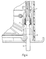
- the drawings show a jigsaw power tool 40 having a clamping mechanism for securely holding saw blades in a central position whatever their thickness (designed for range 0.8mm to 2.0mm thick).
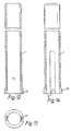
- the clamping mechanism comprises a cup 16 which is fixed to a bayonet washer 6 (shown in more detail in Figures 17 and 18) by welding or crimping to form a combined cup/bayonet washer assembly 17.
- the cup/bayonet washer assembly 17 is rotatably mounted on a larger diameter part 20 of a plunger 1, which prevents the bayonet washer 6 moving up or down the axis of the plunger 1, and a collar 7 is positioned around the cup/bayonet washer assembly 17.
- the collar 7 is located axially by a flange and engages with a locating feature, such as flats, formed on the cup/bayonet washer assembly 17 so as to be rotationally fast therewith.
- a torsion spring 4 is located at one end in a hole 18 in the plunger 1, and at the other end 19 within an actuating wing 14 formed on the collar 7, so that torque is transferred from plunger 1 via the spring 4 and collar 7 to the bayonet washer 6.
- a keeper part 3 mounted within the plunger 1 engages with vertical grooves in the plunger 1 which allow movement of the keeper 3 along the axis of the plunger 1 but prevent rotational movement of the keeper 3 within the plunger.
- the keeper 3 has formed on its lower end a pair of legs 9 which line up with cut-outs 23 in the bayonet washer 6 when the bayonet washer is in its open position.
- the bayonet washer 6 has a slot 22 extending across its diameter, substantially perpendicular to the position of the cut outs 23.
- the upper surface of the bayonet washer 6 has a pair of ramps or cam surfaces 10 which end at the slots 22.
- the clamping mechanism operates thus:
- the torsion spring 4 rotates the bayonet washer 6 anti-clockwise (viewed from below).
- the ramps 10 of the bayonet washer 6 capture ears 11 formed on the sides of the saw blade 13, and urge them upwards until they jam in vee notches 12 in the base of the plunger 1.
- the bayonet washer 6 is jammed and the saw blade 13 is centred.
- the clamping mechanism is now "closed”.
- the user To release the saw blade 13, the user simply pushes on the "wing" 14 of the collar 7, rotating it clockwise (viewed from below). During this movement, the ramps 10 of the bayonet washer 6 release the "ears" 11 of the saw blade 13, so that the saw blade 13 is free to be ejected by the keeper 3 which is pushed down by the compression spring 2 towards the bayonet washer 6.
- the collar 7 will simply spring back (anti-clockwise) until it is stopped by a finger guard 15.
- the keeper is prevented from falling out by its legs 9 being stopped by the top face of the bayonet washer 6.
- the clamping mechanism can then be reset simply by pushing the collar 7 (clockwise) until it latches in the open position.
- the clamping mechanism is ready to receive another saw blade.
Landscapes
- Engineering & Computer Science (AREA)
- Mechanical Engineering (AREA)
- Sawing (AREA)
Claims (13)
- Ein angetriebenes Werkzeug mit einem Einspannmechanismus für ein entfernbares Betriebselement (13), bestehend aus:das Feststellelement (3) verschiebbar im Kolben (1) angebracht ist und eine Zentrierrille (8) aufweist, in die nach Einsetzen des Betriebselements (13) durch die Einsetzöffnung (22) das eingesetzte Ende des Betriebselements (13) eingreift, um das Feststellelement (3) von der Einsetzöffnung (22) wegzudrängen, wodurch es das Feststellelement (3) aus dem Verriegelungselemeht (7) ausrückt und dadurch das Verriegelungselement (7) für Drehung zu seiner geschlossenen Stellung löst.einem Kolben (1);einem Verriegelungselement (7), angebracht im Betriebselement-Empfangsende des Kolbens (1) für Drehung zwischen einer geöffneten Stellung, in der das Betriebselement (13) in die Baugruppe eingesetzt werden kann, und einer geschlossenen Stellung, in der das Entfernen des Betriebselements (13) aus der Baugruppe verhindert wird, wobei das Verriegelungselement (7) eine in einem Ende ausgebildete Betriebselement-Einsetzöffnung (22) aufweist;einem Feststellelement (3), das verschiebbar für Bewegung parallel zur Einsetzrichtung des Betriebselements (13) angebracht ist, wobei das Feststellelement (3) fest mit dem Kolben (1) drehbar ist und mit dem Verriegelungselement (7) eingreifbar ist, um es in der geöffneten Stellung fest zu stellen; undVorbelastungsmitteln (2), das das Feststellelement (3) zur Einsetzöffnung (22) des Verriegelungselements, (7) vorbelastet und dadurch das Feststellelement (3) in einen Feststelleingriff mit dem Verriegelungselement (7) bringt, wenn kein Betriebselement vorhanden ist; dadurch gekennzeichnet, dass
- Ein angetriebenes Werkzeug nach Anspruch 1, in dem das Verriegeluhgselement (7) drehbar um eine Achse parallel zur Einsetzrichtung des Betriebselements (13) ist.
- Ein angetriebenes Werkzeug nach Anspruch 2, weiter umfassend ein erstes Feststellmittel (9), ausgebildet am Feststellelement (3), das mit einem zweiten Feststellmittel (23), ausgebildet am Verriegelungselement (7), in Eingriff kommt, um das Verriegelungselement (7) in der geöffneten Stellung fest zu stellen.
- Ein angetriebenes Werkzeug nach einem der vorstehenden Ansprüche, in dem das erste Feststellmittel (9) aus einer oder mehreren Erhebungen besteht und das Feststellmittel (23) aus einem oder mehreren kooperierenden Vertiefungen im Verriegelungselement (7) besteht.
- Ein angetriebenes Werkzeug nach Anspruch 4, in dem die oder jede Erhebung sich vom Feststellelement (3) zum Verriegelungselement (7) hin in einer Richtung parallel zur Einsetzrichtung des Betriebselements (13) erstreckt.
- Ein angetriebenes Werkzeug nach einem der vorstehenden Ansprüche, in dem der Kolben (1) eine oder mehrere keilförmige (12) Rillen zum Empfang einer korrespondierenden schräg verlaufenden Erhebung (11), die am Betriebselement (13) ausgebildet ist, aufweist.
- Ein angetriebenes Werkzeug nach einem der vorstehenden Ansprüche, in dem das Verriegelungselement (7) so am Kolben (1) angebracht ist, dass es im Wesentlichen gegen Bewegung parallel zur Einsetzrichtung des Betriebselements (13) gehindert ist.
- Ein angetriebenes Werkzeug nach einem der vorstehenden Ansprüche, in dem das Verriegelungselement (7) in seiner Endfläche eine Scheibe (6) enthält, durch die das Betriebselement eingesetzt werden kann.
- Ein angetriebenes Werkzeug nach Anspruch 8, in dem die Einsetzöffnung (22) aus mindestens einem Schlitz (22) besteht, der in der Scheibe (6) zum Empfang einer Erhebung (11) am Betriebselement (13) ausgebildet ist, wodurch das Betriebselement (13) bei der Drehung des Verriegelungselements (7) zu seiner geschlossenen Stellung erfasst wird.
- Ein angetriebenes Werkzeug nach Anspruch 9, in dem die Scheibe (6) weiterhin mindestens eine Nockenoberfläche (10) zum Treiben des Betriebselements (13) in das Werkzeug bei der Drehung des Verriegelungselements (7) zu seiner geschlossenen Stellung aufweist.
- Ein angetriebenes Werkzeug nach Anspruch 10, in dem die Scheibe (6) zwei Nockenoberflächen (10) aufweist, die jeweils mit einer verschiedenen Erhebung (11) des Betriebselements in Eingriff kommen.
- Ein angetriebenes Werkzeug nach Anspruch 11, in dem die zwei Nockenoberflächen (10) jeweils mit ihren zugehörigen Erhebungen bei einer unterschiedlichen Winkelausrichtung der Scheibe (6) in Eingriff kommen.
- Ein angetriebenes Werkzeug nach einem der vorstehenden Ansprüche, das weiterhin ein zweites Vorbelastungsmittel (4) umfasst, das das Verriegelungselement (7) drehend zur geschlossenen Stellung hin drängt.
Applications Claiming Priority (3)
| Application Number | Priority Date | Filing Date | Title |
|---|---|---|---|
| GB9704255 | 1997-02-28 | ||
| GB9704255A GB2322593B (en) | 1997-02-28 | 1997-02-28 | Clamping mechanism for a power tool |
| PCT/EP1998/000624 WO1998038000A1 (en) | 1997-02-28 | 1998-02-05 | Tool clamping mechanism for a power tool |
Publications (2)
| Publication Number | Publication Date |
|---|---|
| EP0906166A1 EP0906166A1 (de) | 1999-04-07 |
| EP0906166B1 true EP0906166B1 (de) | 2003-05-07 |
Family
ID=10808525
Family Applications (1)
| Application Number | Title | Priority Date | Filing Date |
|---|---|---|---|
| EP98906919A Expired - Lifetime EP0906166B1 (de) | 1997-02-28 | 1998-02-05 | Werkzeugeinspannvorrichtung für ein angetriebenes werkzeug |
Country Status (7)
| Country | Link |
|---|---|
| US (1) | US6308425B1 (de) |
| EP (1) | EP0906166B1 (de) |
| JP (1) | JP4020974B2 (de) |
| CN (1) | CN1095710C (de) |
| DE (1) | DE69814280D1 (de) |
| GB (1) | GB2322593B (de) |
| WO (1) | WO1998038000A1 (de) |
Families Citing this family (20)
| Publication number | Priority date | Publication date | Assignee | Title |
|---|---|---|---|---|
| US7325315B2 (en) | 1995-06-09 | 2008-02-05 | Black & Decker Inc. | Clamping arrangement for receiving a saw blade in multiple orientations |
| DE19819530A1 (de) * | 1998-04-30 | 1999-11-04 | Scintilla Ag | Handwerkzeugmaschine |
| DE19819528A1 (de) * | 1998-04-30 | 1999-11-04 | Scintilla Ag | Handwerkzeugmaschine |
| DE29819601U1 (de) * | 1998-11-03 | 2000-03-09 | Scintilla Ag, Solothurn | Handwerkzeugmaschine |
| JP3995895B2 (ja) * | 2000-05-16 | 2007-10-24 | 株式会社マキタ | 往復動切断工具のブレード取り付け装置 |
| CN1278809C (zh) * | 2003-01-13 | 2006-10-11 | 苏州宝时得电动工具有限公司 | 锯条的快换夹紧机构 |
| BR8301911Y1 (pt) * | 2003-03-24 | 2014-03-04 | Starrett Ind E Com Ltda | Disposição construtiva em serra |
| CN2617509Y (zh) * | 2003-04-14 | 2004-05-26 | 苏州宝时得电动工具有限公司 | 工作元件的快换夹紧机构 |
| GB2407532A (en) * | 2003-10-28 | 2005-05-04 | Black & Decker Inc | Clamp assembly for removably mounting a working member |
| US7871080B2 (en) * | 2004-01-16 | 2011-01-18 | Robert Bosch Gmbh | Tool-less blade clamping apparatus for a reciprocating tool |
| US7753246B2 (en) * | 2007-01-31 | 2010-07-13 | Tyco Healthcare Group Lp | Surgical instrument with replaceable loading unit |
| CN101402148B (zh) * | 2007-10-01 | 2011-08-03 | 苏州宝时得电动工具有限公司 | 锯条夹紧装置 |
| US8230607B2 (en) | 2008-05-09 | 2012-07-31 | Milwaukee Electric Tool Corporation | Keyless blade clamp for a power tool |
| IL196764A (en) * | 2009-01-28 | 2013-02-28 | Iscar Ltd | Clamping mechanism |
| JP5558214B2 (ja) | 2010-06-08 | 2014-07-23 | 株式会社マキタ | 往復動切断工具のブレード取り付け装置 |
| US10835972B2 (en) | 2018-03-16 | 2020-11-17 | Milwaukee Electric Tool Corporation | Blade clamp for power tool |
| CN213646136U (zh) | 2018-04-03 | 2021-07-09 | 米沃奇电动工具公司 | 电动工具 |
| USD887806S1 (en) | 2018-04-03 | 2020-06-23 | Milwaukee Electric Tool Corporation | Jigsaw |
| CN114273621A (zh) * | 2021-12-27 | 2022-04-05 | 徐永上 | 一种消失模铸造砂箱 |
| US12420345B2 (en) | 2022-02-22 | 2025-09-23 | Techtronic Cordless Gp | Blade clamp for reciprocating saw |
Family Cites Families (10)
| Publication number | Priority date | Publication date | Assignee | Title |
|---|---|---|---|---|
| BE503358A (de) * | 1950-06-17 | |||
| US3583716A (en) * | 1969-02-06 | 1971-06-08 | Singer Co | Chuck assembly for power tools |
| US4299402A (en) * | 1978-05-02 | 1981-11-10 | Hoffman Simon J | Blade holder for saber saw |
| DE3245359A1 (de) * | 1982-12-08 | 1984-06-14 | Robert Bosch Gmbh, 7000 Stuttgart | Saege, insbesondere motorisch angetriebene handstichsaege |
| DE4138986A1 (de) | 1991-11-27 | 1993-06-03 | Atlas Copco Elektrowerkzeuge | Spanneinrichtung fuer eine stichsaegemaschine |
| US5340129A (en) * | 1993-01-21 | 1994-08-23 | Minnesota Mining And Manufacturing Company | Saw blade retention system |
| DE4311161A1 (de) * | 1993-04-05 | 1994-10-06 | Kress Elektrik Gmbh & Co | Schnellspannvorrichtung für Stichsägeblätter |
| JP2710565B2 (ja) * | 1994-09-29 | 1998-02-10 | リョービ株式会社 | 切断工具 |
| DE19509539A1 (de) * | 1995-03-16 | 1996-09-19 | Bosch Gmbh Robert | Stichsägemaschine |
| DE19521246B4 (de) * | 1995-06-10 | 2006-02-09 | Scintilla Ag | Stichsäge |
-
1997
- 1997-02-28 GB GB9704255A patent/GB2322593B/en not_active Expired - Lifetime
-
1998
- 1998-02-05 CN CN98800213A patent/CN1095710C/zh not_active Expired - Lifetime
- 1998-02-05 DE DE69814280T patent/DE69814280D1/de not_active Expired - Lifetime
- 1998-02-05 WO PCT/EP1998/000624 patent/WO1998038000A1/en not_active Ceased
- 1998-02-05 EP EP98906919A patent/EP0906166B1/de not_active Expired - Lifetime
- 1998-02-05 JP JP53722098A patent/JP4020974B2/ja not_active Expired - Lifetime
- 1998-02-05 US US09/101,647 patent/US6308425B1/en not_active Expired - Lifetime
Also Published As
| Publication number | Publication date |
|---|---|
| US6308425B1 (en) | 2001-10-30 |
| EP0906166A1 (de) | 1999-04-07 |
| DE69814280D1 (de) | 2003-06-12 |
| GB2322593A (en) | 1998-09-02 |
| GB9704255D0 (en) | 1997-04-16 |
| WO1998038000A1 (en) | 1998-09-03 |
| CN1217675A (zh) | 1999-05-26 |
| CN1095710C (zh) | 2002-12-11 |
| JP2000509665A (ja) | 2000-08-02 |
| JP4020974B2 (ja) | 2007-12-12 |
| GB2322593B (en) | 1999-05-05 |
Similar Documents
| Publication | Publication Date | Title |
|---|---|---|
| EP0906166B1 (de) | Werkzeugeinspannvorrichtung für ein angetriebenes werkzeug | |
| US6209208B1 (en) | Keyless blade clamp mechanism | |
| US6735876B2 (en) | Blade clamps suitable for reciprocating power tools | |
| US6161290A (en) | Utility knife | |
| US5601483A (en) | Power tool | |
| US6725548B1 (en) | Keyless blade clamp mechanism | |
| KR960005340B1 (ko) | 인출회전형 문용 록핸들장치 | |
| KR960003351Y1 (ko) | 인출회전형 문짝용 로크핸들장치 | |
| EP0633106B1 (de) | Kappsäge | |
| EP1220727B1 (de) | Angetriebenes futter | |
| EP2394768B1 (de) | Schneidwerkzeugaufspannvorrichtung | |
| EP0634251B1 (de) | Vorrichtung zum leichten Entfernen von verklemmten Heftklammern | |
| JPH06240932A (ja) | 引出し回転型扉用ロックハンドル装置 | |
| WO1997031745A2 (en) | Keyless blade clamp mechanism | |
| US5448027A (en) | Safety switched outlet with dead front | |
| GB2336805A (en) | A hand machine tool chuck | |
| WO2006031655A3 (en) | Push button lock mechanism for a handle set | |
| JPH08109762A (ja) | 引出し回転型扉用ロックハンドル装置 | |
| KR100454857B1 (ko) | 카드조작식쇄정장치 | |
| EP0940210A1 (de) | Sägeblattspannvorrichtung und Säge versehen mit dieser Vorrichtung | |
| GB2344563A (en) | Ejector mechanism for hand tool | |
| EP0473288B1 (de) | Zylinderschloss | |
| JPH1193468A (ja) | 施錠装置 | |
| JPH0636200Y2 (ja) | 引出し回転型扉用ロックハンドル装置 | |
| JPH07305543A (ja) | ハンドルロック |
Legal Events
| Date | Code | Title | Description |
|---|---|---|---|
| PUAI | Public reference made under article 153(3) epc to a published international application that has entered the european phase |
Free format text: ORIGINAL CODE: 0009012 |
|
| AK | Designated contracting states |
Kind code of ref document: A1 Designated state(s): DE GB IT |
|
| 17P | Request for examination filed |
Effective date: 19990303 |
|
| 17Q | First examination report despatched |
Effective date: 20011108 |
|
| GRAH | Despatch of communication of intention to grant a patent |
Free format text: ORIGINAL CODE: EPIDOS IGRA |
|
| GRAH | Despatch of communication of intention to grant a patent |
Free format text: ORIGINAL CODE: EPIDOS IGRA |
|
| GRAA | (expected) grant |
Free format text: ORIGINAL CODE: 0009210 |
|
| AK | Designated contracting states |
Designated state(s): DE GB IT |
|
| REG | Reference to a national code |
Ref country code: GB Ref legal event code: FG4D |
|
| REF | Corresponds to: |
Ref document number: 69814280 Country of ref document: DE Date of ref document: 20030612 Kind code of ref document: P |
|
| PG25 | Lapsed in a contracting state [announced via postgrant information from national office to epo] |
Ref country code: DE Free format text: LAPSE BECAUSE OF FAILURE TO SUBMIT A TRANSLATION OF THE DESCRIPTION OR TO PAY THE FEE WITHIN THE PRESCRIBED TIME-LIMIT Effective date: 20030808 |
|
| PLBE | No opposition filed within time limit |
Free format text: ORIGINAL CODE: 0009261 |
|
| STAA | Information on the status of an ep patent application or granted ep patent |
Free format text: STATUS: NO OPPOSITION FILED WITHIN TIME LIMIT |
|
| 26N | No opposition filed |
Effective date: 20040210 |
|
| PG25 | Lapsed in a contracting state [announced via postgrant information from national office to epo] |
Ref country code: IT Free format text: LAPSE BECAUSE OF NON-PAYMENT OF DUE FEES Effective date: 20050205 |
|
| PGFP | Annual fee paid to national office [announced via postgrant information from national office to epo] |
Ref country code: GB Payment date: 20170221 Year of fee payment: 20 |
|
| REG | Reference to a national code |
Ref country code: GB Ref legal event code: PE20 Expiry date: 20180204 |
|
| PG25 | Lapsed in a contracting state [announced via postgrant information from national office to epo] |
Ref country code: GB Free format text: LAPSE BECAUSE OF EXPIRATION OF PROTECTION Effective date: 20180204 |