EP1220727B1 - Angetriebenes futter - Google Patents
Angetriebenes futter Download PDFInfo
- Publication number
- EP1220727B1 EP1220727B1 EP00948871A EP00948871A EP1220727B1 EP 1220727 B1 EP1220727 B1 EP 1220727B1 EP 00948871 A EP00948871 A EP 00948871A EP 00948871 A EP00948871 A EP 00948871A EP 1220727 B1 EP1220727 B1 EP 1220727B1
- Authority
- EP
- European Patent Office
- Prior art keywords
- shank
- locking element
- opening
- slot
- locking
- Prior art date
- Legal status (The legal status is an assumption and is not a legal conclusion. Google has not performed a legal analysis and makes no representation as to the accuracy of the status listed.)
- Expired - Lifetime
Links
Images


Classifications
-
- B—PERFORMING OPERATIONS; TRANSPORTING
- B23—MACHINE TOOLS; METAL-WORKING NOT OTHERWISE PROVIDED FOR
- B23B—TURNING; BORING
- B23B31/00—Chucks; Expansion mandrels; Adaptations thereof for remote control
- B23B31/02—Chucks
- B23B31/10—Chucks characterised by the retaining or gripping devices or their immediate operating means
- B23B31/113—Retention by bayonet connection
-
- B—PERFORMING OPERATIONS; TRANSPORTING
- B23—MACHINE TOOLS; METAL-WORKING NOT OTHERWISE PROVIDED FOR
- B23B—TURNING; BORING
- B23B2260/00—Details of constructional elements
- B23B2260/136—Springs
-
- Y—GENERAL TAGGING OF NEW TECHNOLOGICAL DEVELOPMENTS; GENERAL TAGGING OF CROSS-SECTIONAL TECHNOLOGIES SPANNING OVER SEVERAL SECTIONS OF THE IPC; TECHNICAL SUBJECTS COVERED BY FORMER USPC CROSS-REFERENCE ART COLLECTIONS [XRACs] AND DIGESTS
- Y10—TECHNICAL SUBJECTS COVERED BY FORMER USPC
- Y10S—TECHNICAL SUBJECTS COVERED BY FORMER USPC CROSS-REFERENCE ART COLLECTIONS [XRACs] AND DIGESTS
- Y10S279/00—Chucks or sockets
- Y10S279/904—Quick change socket
-
- Y—GENERAL TAGGING OF NEW TECHNOLOGICAL DEVELOPMENTS; GENERAL TAGGING OF CROSS-SECTIONAL TECHNOLOGIES SPANNING OVER SEVERAL SECTIONS OF THE IPC; TECHNICAL SUBJECTS COVERED BY FORMER USPC CROSS-REFERENCE ART COLLECTIONS [XRACs] AND DIGESTS
- Y10—TECHNICAL SUBJECTS COVERED BY FORMER USPC
- Y10T—TECHNICAL SUBJECTS COVERED BY FORMER US CLASSIFICATION
- Y10T279/00—Chucks or sockets
- Y10T279/17—Socket type
- Y10T279/17128—Self-grasping
- Y10T279/17162—Yielding detent
-
- Y—GENERAL TAGGING OF NEW TECHNOLOGICAL DEVELOPMENTS; GENERAL TAGGING OF CROSS-SECTIONAL TECHNOLOGIES SPANNING OVER SEVERAL SECTIONS OF THE IPC; TECHNICAL SUBJECTS COVERED BY FORMER USPC CROSS-REFERENCE ART COLLECTIONS [XRACs] AND DIGESTS
- Y10—TECHNICAL SUBJECTS COVERED BY FORMER USPC
- Y10T—TECHNICAL SUBJECTS COVERED BY FORMER US CLASSIFICATION
- Y10T279/00—Chucks or sockets
- Y10T279/17—Socket type
- Y10T279/17761—Side detent
- Y10T279/17769—Pivoted or rotary
- Y10T279/17777—Sleeved
-
- Y—GENERAL TAGGING OF NEW TECHNOLOGICAL DEVELOPMENTS; GENERAL TAGGING OF CROSS-SECTIONAL TECHNOLOGIES SPANNING OVER SEVERAL SECTIONS OF THE IPC; TECHNICAL SUBJECTS COVERED BY FORMER USPC CROSS-REFERENCE ART COLLECTIONS [XRACs] AND DIGESTS
- Y10—TECHNICAL SUBJECTS COVERED BY FORMER USPC
- Y10T—TECHNICAL SUBJECTS COVERED BY FORMER US CLASSIFICATION
- Y10T279/00—Chucks or sockets
- Y10T279/17—Socket type
- Y10T279/17863—Shouldered-tang holding
-
- Y—GENERAL TAGGING OF NEW TECHNOLOGICAL DEVELOPMENTS; GENERAL TAGGING OF CROSS-SECTIONAL TECHNOLOGIES SPANNING OVER SEVERAL SECTIONS OF THE IPC; TECHNICAL SUBJECTS COVERED BY FORMER USPC CROSS-REFERENCE ART COLLECTIONS [XRACs] AND DIGESTS
- Y10—TECHNICAL SUBJECTS COVERED BY FORMER USPC
- Y10T—TECHNICAL SUBJECTS COVERED BY FORMER US CLASSIFICATION
- Y10T408/00—Cutting by use of rotating axially moving tool
- Y10T408/89—Tool or Tool with support
- Y10T408/907—Tool or Tool with support including detailed shank
-
- Y—GENERAL TAGGING OF NEW TECHNOLOGICAL DEVELOPMENTS; GENERAL TAGGING OF CROSS-SECTIONAL TECHNOLOGIES SPANNING OVER SEVERAL SECTIONS OF THE IPC; TECHNICAL SUBJECTS COVERED BY FORMER USPC CROSS-REFERENCE ART COLLECTIONS [XRACs] AND DIGESTS
- Y10—TECHNICAL SUBJECTS COVERED BY FORMER USPC
- Y10T—TECHNICAL SUBJECTS COVERED BY FORMER US CLASSIFICATION
- Y10T408/00—Cutting by use of rotating axially moving tool
- Y10T408/94—Tool-support
- Y10T408/95—Tool-support with tool-retaining means
Definitions
- This invention relates to a power drivable chuck, and particularly relates to a power drivable chuck having a shankresponsive locking element, and to an accessory having a shank configuration which facilitates assembly of the shank with the chuck.
- chucks are designed with an opening for receiving a shank of an accessory, such as a bit, and locking the shank with the chuck.
- the shank is inserted into an opening of a body of the chuck and a key is used to advance jaws within the body, in axial and radially inward directions to clamp about the inserted shank.
- a mechanism is contained within the opening of the body, which is responsive to the insertion of the shank therein, for operating a locking mechanism also contained within the body.
- the locking mechanism includes a rolling element, such as a ball or a roll, which is moved aside from a biased locking position by the incoming shank, and returns to the locking position when an accommodating portion of the shank is aligned with the rolling element.
- a rolling element such as a ball or a roll
- an accessory such as a bit, formed with a shank which facilitates the operation of the shank-locking features of a chuck.
- EP1128923 describes a chuck including a body in which a passage is formed.
- a locking element is moveable within the passage for locking one of a set of bits in the chuck. When a bit is inserted into the opening of the chuck, a portion of the locking element is pushed by the end of the bit rearwardly into passage to allow the bit to be inserted.
- EP1128923 falls under the provisions of Article 54(3)EPC.
- a power drivable chuck comprising the features of claim 1.
- an accessory comprising the features of claim 14.
- this invention contemplates a power drivable chuck for receiving and clamping a shank having at least one axial groove formed in the periphery thereof extending to a free end of the shank, and having a transaxial groove formed in a side wall, along an intermediate portion, of the axial groove.
- the chuck includes a body having an opening therein for receipt of the shank.
- the opening of the body is formed with a wall, and at least one axial rib formed on and extending inward from the wall of the opening of the body for receipt of the axial groove of the shank.
- a locking element is located within the opening of the body.
- Means responsive to the insertion of the free end of the shank into the opening of the body, are provided for facilitating the directing of the locking element into the axial groove of the body to allow the shank to be moved further into the opening.
- Other means responsive to an alignment of the locking element with the transaxial groove, are provided for directing the locking element into the transaxial groove to lock the shank with the chuck.
- This invention further contemplates a power drivable chuck for receiving and clamping a shank having at least one axial groove formed in the periphery thereof extending to a free end of the shank, and having a transaxial groove formed in a side wall, along an intermediate portion, of the axial groove.
- the chuck includes a body having an axis and an axial opening formed therein for receipt of the shank.
- the opening of the body is formed with a wall, with at least one axial rib formed on and extending inward from the wall of the opening of the body for receipt of the axial groove of the shank.
- a slot is formed in the body and has a first end surface at first end thereof and a second end surface at a second end thereof spaced from the first end.
- a locking element is located within the opening of the body and has a portion thereof located within the slot for movement relative thereto within a plane between the first end surface and the second surface of the slot.
- a biasing element is provided for normally urging the locking element into engagement with the first end surface and allowing movement of the locking element toward the second end surface upon the application of a force sufficient to overcome an urging force as applied by the biasing element.
- this invention contemplates an accessory with a shank having an axis and a free end.
- An axial groove is formed in the shank through the free end thereof, and the axial groove is formed with a wall.
- a transaxial groove is formed in the wall of the axial groove at a location spaced inboard from the free end of the shank.
- a chuck 30 can be coupled to a power driver such as, for example, a drill 32, shown in phantom, for rotating the chuck.
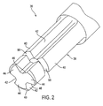
- the chuck 30 is designed with a shank-receiving opening 34 for receiving and locking a bit 36, as shown in Fig. 2 , having a shank 38 with a plurality of spaced, axially-aligned ribs 40, separated by a plurality of axially-aligned grooves 42.
- a free, or rear, end of each of the ribs 40 is formed with a slanting surface 44 ( Fig. 6 ), which slants forwardly from a first side edge 46 to a second edge 48 of the rear end of the rib.
- Each of the ribs 40 is formed with a transaxial groove 50, where all of the grooves are located in a common plane perpendicular to the axis of the bit 36.
- a plurality of bits, having ribs and grooves formed in the shanks, are disclosed in EP1128923 .
- the ribs of the bits disclosed in the above-noted pending patent application may be modified by the formation of a groove, such as the groove 50, to facilitate insertion and locking of the modified bits in the chuck 30.
- the chuck 30 includes a chuck body 52 formed with a plurality of spaced ribs 54, which extend radially inward from an inner wall of the shank-receiving opening 34, with grooves 56 between the ribs.
- the chuck disclosed in the above-identified pending patent application is formed with ribs and grooves in a similar arrangement.
- the chuck body 52 includes three slots 58, each of which is formed.radially through a cylindrical wall 60 of the body adjacent an inboard end of the respective ribs 54 of the body and in a common plane 61 perpendicular to the axis of the body.
- a small hole 62 is formed through the wall 60 of the body at a location to the rear of the plane 61 of the slots 58.
- a latching unit 64 is formed with a movable external element, such as a circular band 66, which is located about the chuck body 52 radially outward of the slots 58, and is further formed with a plurality of locking elements, such as three spaced locking fingers 68, extending radially inward from an inside wall of the band.
- Each of the locking fingers 68 is located within a respective one of the slots 58, as shown in Figs. 3, 4 and 5 , and is movable angularly in the plane 61 between opposite ends of the respective slot.
- a coil spring 70 is located within the opening 34 of the chuck body 52, just rearward of the plane 61.
- the spring 70 is formed with a straight forward end 72, which is located in a small hole in an intermediate portion of one of the locking fingers 68, and a straight rearward end 74, which is located in the opening 62 of the chuck body 52.
- each of the locking fingers 68 is at one end of the respective one of the slots 58, which precludes movement of the band 66 and the fingers in a counterclockwise direction. Also, each of the locking fingers 68 is aligned with, and to the rear of, the slanted surface 44 of a respective one of the ribs 40 of the shank 38.
- each rib 40 engages the respective finger 68 and moves the finger, and the band 66 , in a rotary direction within the plane 61, whereby the spring 70 is being wound in a tensioning direction.
- the fingers 68 are moved angularly in the plane 61 to a position of alignment with a respective one of the grooves 42 of the shank 38, as shown in Fig. 5 .
- the grooves 42 of the shank 38 allow the continued rearward movement of the shank by providing a clear path for the shank past the respective locking fingers 68, which remain in the plane 61.
- the side walls of the grooves 42 restrain the fingers from moving angularly within the plane 61, whereby the spring 70 remains in the tensioned condition.
- the relative axial movement of the grooves 42 of the shank 38 and the fingers 68 is represented in Fig. 6 by the dashed line finger 68a, it being understood that the finger 68a has remained in the plane 61.
- the transaxial groove 50 of the shank is eventually aligned with the plane 61, where the locking fingers 68 are now free of the restraints of the grooves 42 thereon.
- the tensioned spring 70 relaxes to move the locking fingers 68 in a clockwise direction to the limit of the opposite ends of the respective slots 58.
- the fingers 68 are moved into respective ones of the transaxial grooves 50 of the shank 38.
- this movement of the fingers 68 is represented by the dashed line finger 68b in Fig. 6 , it being understood that the finger 68b has remained in the plane 61.
- the bit 3 6 is now locked with the chuck 30, whereby axial movement of the bit relative to the chuck body 52 is precluded as long as the locking fingers 68 remain in the transaxial groove 50.
- the operator When the operator desires to remove the bit 3 6 from the chuck 30, the operator turns the band 66 by hand to move the locking fingers 68 out of the transaxial groove 50 and into alignment with the grooves 42 of the shank 38. The bit 36 can now be withdrawn from the chuck 30.
- the axial width of the transaxial groove 5 0 of the shank 38 can be slightly wider than the width of the locking fingers 68 to provide a firm lock for use of the bit 36, for example, in a rotary drilling operation.
- the transaxial groove 50 of the shank 38 can be somewhat wider than the width of the locking fingers 68 to allow some axial movement of the bit 36, for example, in a hammering or hammer drilling operation.
Claims (14)
- Angetriebenes Futter (30) zur Aufnahme und zum Klemmen eines Schafts (38) mit wenigstens einer axialen Nut (42), die in dessen Umfang ausgebildet ist und sich zu einem freien Ende (40) des Schafts erstreckt, und mit einer quer verlaufenden Nut (50), die in einer Seitenwand entlang eines Zwischenabschnitts der axialen Nut ausgebildet ist, umfassend:einen Körper (52) mit einer Öffnung (34) darin zur Aufnahme des Schafts,wobei die Öffnung des Körpers mit einer Wand ausgebildet ist,
wenigstens eine axiale Rippe (54), die an der Wand der öffnung des Körpers zur Aufnahme der axialen Nut (42) des Schafts ausgebildet ist und sich davon nach innen erstreckt,
ein Verriegelungselement (68), das in der Öffnung des Körpers angeordnet ist,
wobei das Verriegelungselement (68) angepasst ist, sich in Reaktion auf das Einsetzen des freien Endes des Schafts in die Öffnung des Körpers zu drehen, um das Führen des Verriegelungselements in die axiale Nut des Schafts zu erleichtern, um dem Schaft zu ermöglichen, weiter in die Öffnung bewegt zu werden, und
Mittel (70) zum Führen des Verriegelungselements in die quer verlaufende Nut zum Verriegeln des Schafts mit dem Futter in Reaktion auf eine Ausrichtung des Verriegelungselements mit der quer verlaufenden Nut. - Angetriebenes Futter nach Anspruch 1, wobei
die Öffnung und die Rippe jeweils eine vorgeschriebene Größe und einen vorgeschriebenen Aufbau haben zum Aufnehmen und Halten von jedem in einem Futter anbringbaren Schaft aus einer Vielzahl von Schäften mit unterschiedlichen äußeren Abmessungen in Querrichtung. - Angetriebenes Futter nach Anspruch 1 oder 2, wobei
das Verriegelungselement normalerweise in Umfangsrichtung gegenüber der axialen Rippe des Körpers versetzt ist. - Angetriebenes Futter nach einem der vorhergehenden Ansprüche, wobei
das Verriegelungselement auf eine Drehbewegung nur in einer Ebene (61) senkrecht zu einer Achse der Öffnung des Körpers beschränkt ist. - Angetriebenes Futter nach einem der vorhergehenden Ansprüche, ferner aufweisend:eine Anschlagfläche, die an dem Körper ausgebildet ist,wobei das Verriegelungselement in vorgespannter Weise und normalerweise in Eingriff mit der Anschlagfläche gedrückt wird, um das Verriegelungselement zum Auslösen einer Bewegung des Verriegelungselements nach einem Einsetzen des Schafts in die Öffnung des Körpers anzuordnen.
- Angetriebenes Futter nach einem der vorhergehenden Ansprüche, wobei die Mittel zum Erleichtern aufweisen:das Verriegelungselement ist mit einer Fläche ausgebildet, die zum Eingriff mit dem freien Ende des Schafts nach dessen Einsetzen in die Öffnung des Körpers angeordnet wobei das Verriegelungselement in dem Körper für eine Drehbewegung angebracht ist, undein Vorspannelement (70), das in Eingriff mit dem Verriegelungselement für ein ständiges Drücken des Verriegelungselements in eine vorgeschriebene Richtung ist.
- Angetriebenes Futter nach einem der vorhergehenden Ansprüche, wobei die Mittel zum Führen aufweisen:das Verriegelungselement ist in dem Körper für eine Drehbewegung angebracht, undein Vorspannelement (70), das in Eingriff mit dem Verriegelungselement ist, um das Verriegelungselement normalerweise in eine vorgeschriebene Richtung zu drücken.
- Angetriebenes Futter nach Anspruch 1, das ferner aufweist:einen Schlitz (58), der durch den Körper ausgebildet ist, ein bewegliches äußeres Element (66), das außerhalb des Körpers benachbart zu dem dadurch ausgebildeten Schlitz angeordnet ist,wobei das Verriegelungselement an dem beweglichen äußeren Element ausgebildet ist und sich davon nach innen und durch den in dem Körper ausgebildeten Schlitz erstreckt.
- Angetriebenes Futter nach einem der vorhergehenden Ansprüche, das ferner aufweist:einen Schlitz (58), der durch den Körper ausgebildet ist,wobei das Verriegelungselement für eine Bewegung relativ dazu in dem Schlitz angeordnet ist,
wobei der Schlitz eine Länge in radialer Richtung hat, die ausreichend ist, um dem Verriegelungselement zu erlauben, zwischen einer verriegelten Stellung und einer unverriegelten Stellung bewegt zu werden. - Angetriebenes Futter nach Anspruch 8 oder 9, wobei der Schlitz eine erste Endfläche an einem ersten Ende davon und eine zweite Endfläche an einem zweiten Ende davon hat, das beabstandet von dem ersten Ende ist,
wobei das Verriegelungselement in der Öffnung des Körpers angeordnet ist und einen Abschnitt davon hat, der in dem Schlitz und zur Bewegung relativ dazu in einer Ebene (61) zwischen der ersten Endfläche und der zweiten Endfläche des Schlitzes angeordnet ist, und
wobei das Vorspannelement normalerweise das Verriegelungselement in einen Eingriff mit der ersten Endfläche drückt und eine Bewegung des Verriegelungselements zu der zweiten Endfläche bei der Anwendung einer Kraft ermöglicht, die ausreichend ist, um die Druckkraft zu überwinden, die durch das Vorspannelement ausgeübt wird. - Angetriebenes Futter nach Anspruch 10, das ferner aufweist:das Verriegelungselement ist mit einer Fläche ausgebildet, die normalerweise angeordnet ist, um mit dem freien Ende des Schafts einzugreifen und auf dieses zu reagieren, wenn der Schaft in die Öffnung des Körpers eingesetzt wird, um das Verriegelungselement von einer ersten Stellung in eine zweite Stellung zu drücken.
- Angetriebenes Futter nach Anspruch 10 oder 11, das ferner aufweist:der Schlitz ist ein erster Schlitz, der durch den Körper in der Ebene, die die quer verlaufende Ebene (61) ist, ausgebildet ist,wenigstens einen zweiten Schlitz, der in dem Körper in der in Querrichtung verlaufenden Ebene und beabstandet von dem ersten Schlitz ausgebildet ist,wobei das Verriegelungselement ein erstes Verriegelungselement ist,
wenigstens ein zweites Verriegelungselement, das in der Öffnung des Körpers angeordnet ist und einen Abschnitt daran hat, der in dem wenigstens einen zweiten Schlitz zur Bewegung relativ dazu in der in Querrichtung verlaufenden Ebene zwischen der ersten Endfläche und der zweiten Endfläche des Schlitzes angeordnet ist,
wobei das Vorspannelement normalerweise das erste Verriegelungselement und das wenigstens eine zweite Verriegelungselement in Eingriff mit den entsprechenden ersten Endflächen drückt und eine Bewegung der Endflächen drückt und eine Bewegung der Verriegelungselemente zu den entsprechenden zweiten Endflächen ermöglicht, wenn eine Kraft ausreichend zum Überwinden einer Druckkraft, wie sie von dem Vorspannelement ausgeübt wird, ausgeübt wird. - Angetriebenes Futter nach Anspruch 12 ferner aufweisend:einen ringförmigen Bund (66), der außerhalb des Körpers in der in Querrichtung verlaufenden Ebene angeordnet ist und relativ zu dem Körper beweglich ist,wobei die Verriegelungselemente (68) an dem ringförmigen Bund an beabstandeten Positionen davon ausgebildet sind und sich davon nach innen und durch die entsprechenden Schlitze erstrecken, wobei die Verriegelungselemente in den entsprechenden Schlitzen beweglich sind, wenn sich der ringförmige Bund bewegt.
- Zusatzelement (36) mit:einem Schaft (38) mit wenigstens einer axialen Nut (42), die in dem Umfang davon ausgebildet ist und sich zu einem freien Ende (40) des Schafts erstreckt, und mit einer in Querrichtung verlaufenden Nut (50), die in einer Seitenwand entlang eines mittleren Abschnitts der axialen Nut ausgebildet ist, undwobei das freie Ende des Schafts mit wenigstens einer abgeschrägten Fläche (44) ausgebildet ist, die sich von einer ersten Kante (46) an einer ersten Seite des Schafts zu einer zweiten Kante (48) an einer zweiten Seite des Schafts neigt, die im Allgemeinen gegenüber der ersten Seite des Schafts angeordnet ist.
Applications Claiming Priority (3)
| Application Number | Priority Date | Filing Date | Title |
|---|---|---|---|
| US14482799P | 1999-07-21 | 1999-07-21 | |
| US144827P | 1999-07-21 | ||
| PCT/US2000/019945 WO2001007186A1 (en) | 1999-07-21 | 2000-07-21 | Power drivable chuck |
Publications (3)
| Publication Number | Publication Date |
|---|---|
| EP1220727A1 EP1220727A1 (de) | 2002-07-10 |
| EP1220727A4 EP1220727A4 (de) | 2004-12-15 |
| EP1220727B1 true EP1220727B1 (de) | 2008-12-24 |
Family
ID=22510324
Family Applications (1)
| Application Number | Title | Priority Date | Filing Date |
|---|---|---|---|
| EP00948871A Expired - Lifetime EP1220727B1 (de) | 1999-07-21 | 2000-07-21 | Angetriebenes futter |
Country Status (7)
| Country | Link |
|---|---|
| US (1) | US6390739B1 (de) |
| EP (1) | EP1220727B1 (de) |
| CN (2) | CN1597202A (de) |
| AT (1) | ATE418410T1 (de) |
| AU (1) | AU6230600A (de) |
| DE (1) | DE60041200D1 (de) |
| WO (1) | WO2001007186A1 (de) |
Families Citing this family (25)
| Publication number | Priority date | Publication date | Assignee | Title |
|---|---|---|---|---|
| CN1331628C (zh) * | 1999-07-21 | 2007-08-15 | 布莱克-德克尔公司 | 动力驱动夹头 |
| DE10058587A1 (de) * | 2000-11-25 | 2002-05-29 | Hilti Ag | Vorrichtung zur Drehmomentübertragung |
| US20030078311A1 (en) | 2001-10-19 | 2003-04-24 | Ulrich Muller | Process for the alkoxylation of organic compounds in the presence of novel framework materials |
| DE20203129U1 (de) * | 2002-02-27 | 2002-05-08 | Quanz Reiner | Rotierendes Werkzeug mit einem Einspannschaft |
| EP1535704B1 (de) * | 2003-11-26 | 2010-03-10 | HILTI Aktiengesellschaft | Werkzeugaufnahme für ein drehendes und schlagendes Werkzeug |
| US8132990B2 (en) * | 2003-12-23 | 2012-03-13 | Lynn Everett Bauman | Bit holding apparatus for use with a power tool |
| US7354230B2 (en) | 2003-12-23 | 2008-04-08 | Lynn Bauman | Bit holding apparatus for use with a power tool |
| US7752946B2 (en) * | 2006-04-04 | 2010-07-13 | Shyh-Ming Wang | Socket for wrenches |
| US20070227311A1 (en) * | 2006-04-04 | 2007-10-04 | Shyh-Ming Wang | Socket for a wrench |
| EP2214856B1 (de) | 2007-11-29 | 2016-04-13 | Airbus Operations GmbH | Verfahren zur kodierung einer bohrvorrichtung |
| US8800999B2 (en) * | 2009-02-27 | 2014-08-12 | Black & Decker Inc. | Bit retention device |
| US8622401B2 (en) * | 2009-02-27 | 2014-01-07 | Black & Decker Inc. | Bit retention device |
| US8381830B2 (en) | 2009-05-05 | 2013-02-26 | Black & Decker Inc. | Power tool with integrated bit retention device |
| CN201446519U (zh) * | 2009-06-05 | 2010-05-05 | 南京德朔实业有限公司 | 电动工具 |
| CN102059569A (zh) * | 2010-10-29 | 2011-05-18 | 无锡迪奥机械有限公司 | 自动车床的夹紧夹头 |
| US9254525B2 (en) * | 2011-08-22 | 2016-02-09 | Mst Corporation | Shrink fit tool holder |
| US9227309B2 (en) | 2012-02-15 | 2016-01-05 | Black & Decker Inc. | Quick change bit holder with ring magnet |
| US9156147B2 (en) | 2012-02-15 | 2015-10-13 | Black & Decker Inc. | Quick change bit holder with ring magnet |
| US10150205B2 (en) | 2012-02-15 | 2018-12-11 | Black & Decker Inc. | Fastening tools with floating magnet sleeves |
| US9505108B2 (en) | 2012-02-15 | 2016-11-29 | Black & Decker Inc. | Bit holder with floating magnet sleeve |
| US9943946B2 (en) | 2012-02-15 | 2018-04-17 | Black & Decker Inc. | Tool bits with floating magnet sleeves |
| USD789761S1 (en) | 2015-11-02 | 2017-06-20 | Black & Decker Inc. | Torsion bit |
| AT15846U1 (de) * | 2017-03-14 | 2018-07-15 | Ceratizit Austria Gmbh | Schneidwerkzeug für die rotatorische Bearbeitung eines Werkstücks |
| EP3424645B1 (de) * | 2017-07-07 | 2021-05-05 | Von Arx AG | Kupplung zur verbindung eines werkzeugwechselkopfes mit einem maschinenteil eines pressgeräts |
| CN110449605B (zh) * | 2019-07-03 | 2021-02-12 | 广州通发智能装备股份有限公司 | 一种高稳固加工的数控车床 |
Family Cites Families (13)
| Publication number | Priority date | Publication date | Assignee | Title |
|---|---|---|---|---|
| US1034723A (en) * | 1911-04-01 | 1912-08-06 | Mueller Mfg Co H | Tool-retaining device for boring-bars. |
| US1138465A (en) | 1914-11-19 | 1915-05-04 | North Bros Mfg Co | Chuck. |
| US1311961A (en) * | 1918-05-31 | 1919-08-05 | Gairing Needham Tool Co Inc | Gage for floating-tool holders. |
| US1413101A (en) * | 1920-08-27 | 1922-04-18 | Samuel J Cushing | Tool holder |
| US2387339A (en) * | 1943-08-21 | 1945-10-23 | George J Meyer | Chuck |
| US2393424A (en) * | 1945-01-11 | 1946-01-22 | Howard I Selch | Boring or like tool |
| BR9107043A (pt) | 1990-10-16 | 1993-09-14 | Bosch Gmbh Robert | Dispositivo em maquinas-ferramenta portateis |
| US5316323A (en) * | 1993-01-08 | 1994-05-31 | Victor Jovanovic | Two-part tool holding fixture |
| US5398946A (en) | 1993-12-29 | 1995-03-21 | Poly-Tech Industries | Chuck having one-step lock and release |
| FR2748304B1 (fr) * | 1996-05-02 | 1998-06-26 | Lemforder Nacam Sa | Dispositif d'accouplement de deux arbres |
| US6053675A (en) * | 1998-06-26 | 2000-04-25 | Black & Decker Inc. | Quick-acting tool bit holder |
| US6053765A (en) * | 1998-10-16 | 2000-04-25 | Lear Automotive Dearborn, Inc. | Electrical connector incorporating a light |
| WO2000027574A1 (en) * | 1998-11-12 | 2000-05-18 | Black & Decker Inc. | Chuck, bit, assembly thereof and methods of mounting |
-
2000
- 2000-07-21 WO PCT/US2000/019945 patent/WO2001007186A1/en active Application Filing
- 2000-07-21 CN CN200410085623.XA patent/CN1597202A/zh active Pending
- 2000-07-21 EP EP00948871A patent/EP1220727B1/de not_active Expired - Lifetime
- 2000-07-21 US US09/621,083 patent/US6390739B1/en not_active Expired - Fee Related
- 2000-07-21 AU AU62306/00A patent/AU6230600A/en not_active Abandoned
- 2000-07-21 CN CN00813137.6A patent/CN1250365C/zh not_active Expired - Fee Related
- 2000-07-21 DE DE60041200T patent/DE60041200D1/de not_active Expired - Fee Related
- 2000-07-21 AT AT00948871T patent/ATE418410T1/de not_active IP Right Cessation
Also Published As
| Publication number | Publication date |
|---|---|
| AU6230600A (en) | 2001-02-13 |
| CN1374896A (zh) | 2002-10-16 |
| CN1597202A (zh) | 2005-03-23 |
| ATE418410T1 (de) | 2009-01-15 |
| CN1250365C (zh) | 2006-04-12 |
| EP1220727A1 (de) | 2002-07-10 |
| DE60041200D1 (de) | 2009-02-05 |
| EP1220727A4 (de) | 2004-12-15 |
| WO2001007186A1 (en) | 2001-02-01 |
| US6390739B1 (en) | 2002-05-21 |
Similar Documents
| Publication | Publication Date | Title |
|---|---|---|
| EP1220727B1 (de) | Angetriebenes futter | |
| US6533291B2 (en) | Chuck having quick change mechanism | |
| US4184692A (en) | Motor quick-change chuck system for tool having cylindrically shaped adapter portion | |
| US6517088B1 (en) | Lockable drill chuck | |
| US4188041A (en) | Motor quick-change chuck system for tool having cylindrically shaped adapter portion | |
| US4395170A (en) | Drill, drill chuck, and methods of chucking and unchucking | |
| US7654779B2 (en) | Power tool | |
| US6902358B2 (en) | Power drivable chuck | |
| US6092814A (en) | Tool holder for inserted tools in drilling and/or hammering machines | |
| US4234277A (en) | Motor quick-change chuck system for tool having cylindrically shaped adapter portion | |
| EP1857209B1 (de) | Werkzeuglose Blattspannvorrichtung für hin- und hergehendes Werkzeug | |
| US7469909B2 (en) | Chuck for receiving tools operated by rotating around the axis thereof | |
| US7431308B2 (en) | Tool-holding chuck for equipping a rotating machine, provided with sequenced radial and axial locking means | |
| US5988957A (en) | Quick clamp | |
| US6488451B1 (en) | Drive shaft lock | |
| KR101786137B1 (ko) | 다중-비트 공구 | |
| US20040146367A1 (en) | Guide mechanism for power drill | |
| EP1534453B1 (de) | Schnellspannendes spannfutter | |
| JP2002011677A (ja) | 工具収容装置 | |
| US4273344A (en) | Motor quick-change chuck system for tool having cylindrically shaped adapter portion | |
| US5129662A (en) | Chuck | |
| US5526721A (en) | Tool having switchable pin-shaped tool elements | |
| GB2423948A (en) | Tool holder for a hand held power tool | |
| US5464231A (en) | Chuck with jaws having curved engagement surfaces | |
| JPH07266181A (ja) | 手持式工作機械の工具ホルダ用のロック装置 |
Legal Events
| Date | Code | Title | Description |
|---|---|---|---|
| PUAI | Public reference made under article 153(3) epc to a published international application that has entered the european phase |
Free format text: ORIGINAL CODE: 0009012 |
|
| 17P | Request for examination filed |
Effective date: 20020220 |
|
| AK | Designated contracting states |
Kind code of ref document: A1 Designated state(s): AT BE CH CY DE DK ES FI FR GB GR IE IT LI LU MC NL PT SE |
|
| AX | Request for extension of the european patent |
Free format text: AL;LT;LV;MK;RO;SI |
|
| A4 | Supplementary search report drawn up and despatched |
Effective date: 20041028 |
|
| RIC1 | Information provided on ipc code assigned before grant |
Ipc: 7B 23B 31/113 B Ipc: 7B 23B 31/103 A |
|
| 17Q | First examination report despatched |
Effective date: 20060316 |
|
| GRAP | Despatch of communication of intention to grant a patent |
Free format text: ORIGINAL CODE: EPIDOSNIGR1 |
|
| GRAS | Grant fee paid |
Free format text: ORIGINAL CODE: EPIDOSNIGR3 |
|
| GRAA | (expected) grant |
Free format text: ORIGINAL CODE: 0009210 |
|
| AK | Designated contracting states |
Kind code of ref document: B1 Designated state(s): AT BE CH CY DE DK ES FI FR GB GR IE IT LI LU MC NL PT SE |
|
| REG | Reference to a national code |
Ref country code: GB Ref legal event code: FG4D |
|
| REG | Reference to a national code |
Ref country code: CH Ref legal event code: EP |
|
| REG | Reference to a national code |
Ref country code: IE Ref legal event code: FG4D |
|
| REF | Corresponds to: |
Ref document number: 60041200 Country of ref document: DE Date of ref document: 20090205 Kind code of ref document: P |
|
| PG25 | Lapsed in a contracting state [announced via postgrant information from national office to epo] |
Ref country code: FI Free format text: LAPSE BECAUSE OF FAILURE TO SUBMIT A TRANSLATION OF THE DESCRIPTION OR TO PAY THE FEE WITHIN THE PRESCRIBED TIME-LIMIT Effective date: 20081224 Ref country code: NL Free format text: LAPSE BECAUSE OF FAILURE TO SUBMIT A TRANSLATION OF THE DESCRIPTION OR TO PAY THE FEE WITHIN THE PRESCRIBED TIME-LIMIT Effective date: 20081224 |
|
| NLV1 | Nl: lapsed or annulled due to failure to fulfill the requirements of art. 29p and 29m of the patents act | ||
| PG25 | Lapsed in a contracting state [announced via postgrant information from national office to epo] |
Ref country code: BE Free format text: LAPSE BECAUSE OF FAILURE TO SUBMIT A TRANSLATION OF THE DESCRIPTION OR TO PAY THE FEE WITHIN THE PRESCRIBED TIME-LIMIT Effective date: 20081224 Ref country code: ES Free format text: LAPSE BECAUSE OF FAILURE TO SUBMIT A TRANSLATION OF THE DESCRIPTION OR TO PAY THE FEE WITHIN THE PRESCRIBED TIME-LIMIT Effective date: 20090404 |
|
| PG25 | Lapsed in a contracting state [announced via postgrant information from national office to epo] |
Ref country code: SE Free format text: LAPSE BECAUSE OF FAILURE TO SUBMIT A TRANSLATION OF THE DESCRIPTION OR TO PAY THE FEE WITHIN THE PRESCRIBED TIME-LIMIT Effective date: 20090324 Ref country code: PT Free format text: LAPSE BECAUSE OF FAILURE TO SUBMIT A TRANSLATION OF THE DESCRIPTION OR TO PAY THE FEE WITHIN THE PRESCRIBED TIME-LIMIT Effective date: 20090525 Ref country code: AT Free format text: LAPSE BECAUSE OF FAILURE TO SUBMIT A TRANSLATION OF THE DESCRIPTION OR TO PAY THE FEE WITHIN THE PRESCRIBED TIME-LIMIT Effective date: 20081224 |
|
| PG25 | Lapsed in a contracting state [announced via postgrant information from national office to epo] |
Ref country code: DK Free format text: LAPSE BECAUSE OF FAILURE TO SUBMIT A TRANSLATION OF THE DESCRIPTION OR TO PAY THE FEE WITHIN THE PRESCRIBED TIME-LIMIT Effective date: 20081224 |
|
| PLBE | No opposition filed within time limit |
Free format text: ORIGINAL CODE: 0009261 |
|
| STAA | Information on the status of an ep patent application or granted ep patent |
Free format text: STATUS: NO OPPOSITION FILED WITHIN TIME LIMIT |
|
| PGFP | Annual fee paid to national office [announced via postgrant information from national office to epo] |
Ref country code: GB Payment date: 20090727 Year of fee payment: 10 Ref country code: DE Payment date: 20090729 Year of fee payment: 10 |
|
| 26N | No opposition filed |
Effective date: 20090925 |
|
| PG25 | Lapsed in a contracting state [announced via postgrant information from national office to epo] |
Ref country code: MC Free format text: LAPSE BECAUSE OF NON-PAYMENT OF DUE FEES Effective date: 20090731 |
|
| REG | Reference to a national code |
Ref country code: CH Ref legal event code: PL |
|
| REG | Reference to a national code |
Ref country code: FR Ref legal event code: ST Effective date: 20100331 |
|
| REG | Reference to a national code |
Ref country code: IE Ref legal event code: MM4A |
|
| PG25 | Lapsed in a contracting state [announced via postgrant information from national office to epo] |
Ref country code: FR Free format text: LAPSE BECAUSE OF NON-PAYMENT OF DUE FEES Effective date: 20090731 Ref country code: CH Free format text: LAPSE BECAUSE OF NON-PAYMENT OF DUE FEES Effective date: 20090731 Ref country code: LI Free format text: LAPSE BECAUSE OF NON-PAYMENT OF DUE FEES Effective date: 20090731 |
|
| PGFP | Annual fee paid to national office [announced via postgrant information from national office to epo] |
Ref country code: IT Payment date: 20090728 Year of fee payment: 10 |
|
| PG25 | Lapsed in a contracting state [announced via postgrant information from national office to epo] |
Ref country code: IE Free format text: LAPSE BECAUSE OF NON-PAYMENT OF DUE FEES Effective date: 20090721 |
|
| PG25 | Lapsed in a contracting state [announced via postgrant information from national office to epo] |
Ref country code: GR Free format text: LAPSE BECAUSE OF FAILURE TO SUBMIT A TRANSLATION OF THE DESCRIPTION OR TO PAY THE FEE WITHIN THE PRESCRIBED TIME-LIMIT Effective date: 20090325 |
|
| GBPC | Gb: european patent ceased through non-payment of renewal fee |
Effective date: 20100721 |
|
| PG25 | Lapsed in a contracting state [announced via postgrant information from national office to epo] |
Ref country code: DE Free format text: LAPSE BECAUSE OF NON-PAYMENT OF DUE FEES Effective date: 20110201 Ref country code: LU Free format text: LAPSE BECAUSE OF NON-PAYMENT OF DUE FEES Effective date: 20090721 |
|
| REG | Reference to a national code |
Ref country code: DE Ref legal event code: R119 Ref document number: 60041200 Country of ref document: DE Effective date: 20110201 |
|
| PG25 | Lapsed in a contracting state [announced via postgrant information from national office to epo] |
Ref country code: IT Free format text: LAPSE BECAUSE OF NON-PAYMENT OF DUE FEES Effective date: 20100721 |
|
| PG25 | Lapsed in a contracting state [announced via postgrant information from national office to epo] |
Ref country code: GB Free format text: LAPSE BECAUSE OF NON-PAYMENT OF DUE FEES Effective date: 20100721 |
|
| PG25 | Lapsed in a contracting state [announced via postgrant information from national office to epo] |
Ref country code: CY Free format text: LAPSE BECAUSE OF FAILURE TO SUBMIT A TRANSLATION OF THE DESCRIPTION OR TO PAY THE FEE WITHIN THE PRESCRIBED TIME-LIMIT Effective date: 20081224 |