EP0904940B1 - Tintenversorgungsvorrichtung - Google Patents
Tintenversorgungsvorrichtung Download PDFInfo
- Publication number
- EP0904940B1 EP0904940B1 EP98307391A EP98307391A EP0904940B1 EP 0904940 B1 EP0904940 B1 EP 0904940B1 EP 98307391 A EP98307391 A EP 98307391A EP 98307391 A EP98307391 A EP 98307391A EP 0904940 B1 EP0904940 B1 EP 0904940B1
- Authority
- EP
- European Patent Office
- Prior art keywords
- ink
- package
- film material
- shape
- print head
- Prior art date
- Legal status (The legal status is an assumption and is not a legal conclusion. Google has not performed a legal analysis and makes no representation as to the accuracy of the status listed.)
- Expired - Lifetime
Links
- 238000007789 sealing Methods 0.000 claims description 91
- 239000000463 material Substances 0.000 claims description 79
- 238000007639 printing Methods 0.000 claims description 33
- 230000000149 penetrating effect Effects 0.000 claims description 13
- 230000000452 restraining effect Effects 0.000 claims description 12
- 229920013716 polyethylene resin Polymers 0.000 claims description 4
- 239000000976 ink Substances 0.000 description 483
- 239000004743 Polypropylene Substances 0.000 description 13
- 238000005304 joining Methods 0.000 description 13
- 238000007641 inkjet printing Methods 0.000 description 10
- 230000005499 meniscus Effects 0.000 description 9
- 238000000034 method Methods 0.000 description 9
- 230000007423 decrease Effects 0.000 description 6
- 239000007788 liquid Substances 0.000 description 6
- 238000003825 pressing Methods 0.000 description 6
- 239000003086 colorant Substances 0.000 description 4
- 230000009545 invasion Effects 0.000 description 4
- 238000005086 pumping Methods 0.000 description 4
- 230000015572 biosynthetic process Effects 0.000 description 3
- 238000004090 dissolution Methods 0.000 description 3
- 238000010438 heat treatment Methods 0.000 description 3
- 238000004519 manufacturing process Methods 0.000 description 3
- 238000005728 strengthening Methods 0.000 description 3
- 239000004677 Nylon Substances 0.000 description 2
- 229930040373 Paraformaldehyde Natural products 0.000 description 2
- 230000003247 decreasing effect Effects 0.000 description 2
- 238000001035 drying Methods 0.000 description 2
- 229920001778 nylon Polymers 0.000 description 2
- 239000005020 polyethylene terephthalate Substances 0.000 description 2
- 229920000139 polyethylene terephthalate Polymers 0.000 description 2
- 229920006324 polyoxymethylene Polymers 0.000 description 2
- -1 polypropylene Polymers 0.000 description 2
- 238000010926 purge Methods 0.000 description 2
- 239000000758 substrate Substances 0.000 description 2
- XLYOFNOQVPJJNP-UHFFFAOYSA-N water Substances O XLYOFNOQVPJJNP-UHFFFAOYSA-N 0.000 description 2
- 239000004952 Polyamide Substances 0.000 description 1
- 239000005062 Polybutadiene Substances 0.000 description 1
- 239000004642 Polyimide Substances 0.000 description 1
- 229910000639 Spring steel Inorganic materials 0.000 description 1
- 239000000853 adhesive Substances 0.000 description 1
- 239000012790 adhesive layer Substances 0.000 description 1
- NTXGQCSETZTARF-UHFFFAOYSA-N buta-1,3-diene;prop-2-enenitrile Chemical compound C=CC=C.C=CC#N NTXGQCSETZTARF-UHFFFAOYSA-N 0.000 description 1
- 239000000919 ceramic Substances 0.000 description 1
- 230000008602 contraction Effects 0.000 description 1
- 230000000694 effects Effects 0.000 description 1
- 239000013013 elastic material Substances 0.000 description 1
- 239000000284 extract Substances 0.000 description 1
- 229920001684 low density polyethylene Polymers 0.000 description 1
- 239000004702 low-density polyethylene Substances 0.000 description 1
- 238000002844 melting Methods 0.000 description 1
- 230000008018 melting Effects 0.000 description 1
- 239000002184 metal Substances 0.000 description 1
- 238000002156 mixing Methods 0.000 description 1
- 229920002647 polyamide Polymers 0.000 description 1
- 229920002857 polybutadiene Polymers 0.000 description 1
- 229920001721 polyimide Polymers 0.000 description 1
- 229920000098 polyolefin Polymers 0.000 description 1
- 229920001155 polypropylene Polymers 0.000 description 1
- 229920000915 polyvinyl chloride Polymers 0.000 description 1
- 239000004800 polyvinyl chloride Substances 0.000 description 1
- 229920005989 resin Polymers 0.000 description 1
- 239000011347 resin Substances 0.000 description 1
- 229910001220 stainless steel Inorganic materials 0.000 description 1
- 239000010935 stainless steel Substances 0.000 description 1
- 229920003002 synthetic resin Polymers 0.000 description 1
- 239000000057 synthetic resin Substances 0.000 description 1
Images


Classifications
-
- B—PERFORMING OPERATIONS; TRANSPORTING
- B41—PRINTING; LINING MACHINES; TYPEWRITERS; STAMPS
- B41J—TYPEWRITERS; SELECTIVE PRINTING MECHANISMS, i.e. MECHANISMS PRINTING OTHERWISE THAN FROM A FORME; CORRECTION OF TYPOGRAPHICAL ERRORS
- B41J2/00—Typewriters or selective printing mechanisms characterised by the printing or marking process for which they are designed
- B41J2/005—Typewriters or selective printing mechanisms characterised by the printing or marking process for which they are designed characterised by bringing liquid or particles selectively into contact with a printing material
- B41J2/01—Ink jet
- B41J2/17—Ink jet characterised by ink handling
- B41J2/175—Ink supply systems ; Circuit parts therefor
- B41J2/17503—Ink cartridges
- B41J2/17506—Refilling of the cartridge
- B41J2/17509—Whilst mounted in the printer
-
- B—PERFORMING OPERATIONS; TRANSPORTING
- B41—PRINTING; LINING MACHINES; TYPEWRITERS; STAMPS
- B41J—TYPEWRITERS; SELECTIVE PRINTING MECHANISMS, i.e. MECHANISMS PRINTING OTHERWISE THAN FROM A FORME; CORRECTION OF TYPOGRAPHICAL ERRORS
- B41J2/00—Typewriters or selective printing mechanisms characterised by the printing or marking process for which they are designed
- B41J2/005—Typewriters or selective printing mechanisms characterised by the printing or marking process for which they are designed characterised by bringing liquid or particles selectively into contact with a printing material
- B41J2/01—Ink jet
- B41J2/17—Ink jet characterised by ink handling
- B41J2/175—Ink supply systems ; Circuit parts therefor
Definitions
- the invention relates to an ink supplying device which makes it possible to apply negative pressure to ink to be supplied into a print head, without use of a device for adjusting ink supplying pressure.
- ink supplied to a print head is jetted out from multiple nozzles to perform printing.
- ink jetting ability is kept by making the liquid surface of the ink supplied into the nozzle in the print head into a meniscus (curved surface) in a concave form.
- the ink liquid surface in a meniscus form is formed by adjusting the ink supplying pressure for the ink supplied into the nozzle of the print head into a negative pressure.
- the ink supplying pressure is adjusted by a difference in level between the ink print head and the ink package.
- the difference in level between the ink package and the print head occurs so as to cause a difference in the head of negative pressures.
- the ink supplying pressure is adjusted into a negative pressure.
- a feeding mechanism for feeding printing paper and other devices are disposed below the ink head, and consequently the position and the space for disposing an ink package are limited. Accordingly, in order to dispose an ink package at the limited position or space, it is necessary to make the capacity of the ink package small and frequently exchange the ink package.
- a method is proposed that a small-sized sub-tank is arranged near and below an ink head and an ink package having a large volume is separately arranged as a main tank at a desired position.
- the ink inside the ink package is supplied to the sub-tank arranged near and below the print head by pumping it up, and the ink supplied into the sub-tank is supplied into a print head under the condition that its ink supplying pressure is adjusted into a negative pressure. Since such a small-sized tank has a small capacity, it can be easily arranged near and below the print head. Furthermore, the volume of the ink package does not have to be downsized, since it is separately arranged at a desired position.
- inks of four colors including black, yellow, cyan, and magenta are jetted out from multiple nozzles to perform color printing.
- the ink jetting ability is maintained uniform by forming the liquid surface of the ink supplied into the nozzle of the printer head into a concave meniscus (curved surface).
- the ink surface is formed into a meniscus form, for example, by adjusting the ink supplying pressure for the ink to be supplied into the nozzle of the printer into a negative pressure within a specific range. Therefore, it is possible to keep the ink jetting ability for the respective inks uniform by maintaining the ink supplying pressures substantially equal for the respective inks.
- the ink supplying pressure is adjusted by a difference in level between the ink head and ink packages in which the inks of the respective colors are disposed.
- the respective ink packages are adjacently arranged near and below the printer head and at substantially the same levels so as to make level-differences of the printer head from the respective ink packages substantially equal.
- the printer in order to provide a space where the respective ink packages are adjacently arranged in the horizontal (lateral) direction, it is necessary that the length in the lateral direction of the printer is long.
- the printer that has a long length in the lateral direction is set on a desk or other piece of furniture, the majority of the surface of the desk is occupied by the printer. This is not preferable.
- the multiple ink packages are not arranged in the horizontal direction, but are stacked in the vertical direction. This makes it possible to make the length in the lateral direction of the printer short, and consequently the printer-setting area is reduced.
- a working space on the desk or other piece of furniture can be effectively used.
- US 5448818A discloses a collapsible ink reservoir structure with a conventional arrangement for generating negative pressure.
- Another object of the invention is to provide an ink cartridge for use with such an ink supplying device.
- Another object of the invention is to provide an ink package for use with such an ink supplying device.
- a further object of the invention is to provide an ink package that makes it possible to maintain the ink jetting ability uniform for multiple types of inks to be supplied to printer heads.
- an ink supplying device for supplying ink used for printing to a print head according to claim 1 is provided, which includes an ink package for sealing the ink, having a laminated structure in which multiple film sheets formed of polyethylene resin or other similar material are laminated, and made of a film material having a shape restoring property, and an ink extracting member having a needle-like tip portion which is stuck into the ink package, for extracting the ink from the ink package by sticking the needle-like tip portion into the ink package, and supplying the extracted ink into the print head.
- the needle-like tip portion of the ink extracting member is stuck into the ink package so that the ink extracting member penetrates into the ink package.
- the ink sealed inside the ink package is extracted with the ink extracting member and supplied into the print head to be used with the print head for printing.
- the ink package is made of a film material having a laminated structure in which a plurality of film sheets formed of polyethylene resin or other similar material are laminated.
- the film material intimately contacts the outer surface of the ink extracting member stuck into the ink package. Therefore, when the ink extracting member is stuck into the ink package, it is possible to prevent leakage of ink from the ink package and invasion of air and the like into the ink package.
- the film material forming the ink package has a shape restoring ability and consequently it is possible to restrain a change in the shape of the ink package caused by a difference between the inner and outer pressures of the ink package.
- the ink package may have an ink sealing portion for sealing the ink, and a part of the outer surface of the ink sealing portion is formed into a substantial plane or concave form.
- the needle tip portion of the ink extracting member is stuck into the outer surface in a substantial plane or concave form of the ink sealing portion, so that the ink extracting member penetrates into the ink sealing member.
- the ink extracting member can be easily stuck into the ink sealing portion of the ink package so as to penetrate into the portion, since a part of the outer surface of the ink sealing portion of the ink package is formed into a substantial plane or concave form.
- both sides of the film material may be melt-joined, whereby the outer surface of the ink sealing portion formed into a substantial plane or concave form is made on a face crossing both of the sides that are melt-joined.
- the ink package is separately equipped with any member for making the outer surface of the ink package into a substantial plane or concave form, thereby simplifying the steps of making the ink package and reducing the cost of manufacture.
- the film material forming the ink sealing portion may have a thickness of approximately 30 ⁇ m to 300 ⁇ m.
- the shape restoring ability of the film material can be improved, since the film material is formed to have a thickness of approximately 30 ⁇ m to approximately 300 ⁇ m.
- the negative pressure applied to ink supplied into the print head can also be maintained within the range that the print head can be operated, since the formation of the film material having a thickness of approximately 300 ⁇ m or less restrains an excessive increase in the negative pressure applied into the ink package.
- the ink extracting member can also be easily stuck and inserted into the ink package, since the film material is formed to have a thickness of approximately 300 ⁇ m or less.
- the ink package may have an ink sealing portion for sealing the ink, and the longitudinal length of the ink sealing portion is approximately ten times or less as long as the lateral length thereof.
- the shape restoring ability of the film material forming the ink package can be improved, since the length in the longitudinal direction is approximately ten times or less as long as the length in the lateral direction, about the ink sealing portion of the ink package.
- the ink package may have an ink sealing portion for sealing up the ink, and one of the longitudinal length and the lateral length of the ink sealing portion is approximately 200 mm or less.
- the shape restoring ability of the film material forming the ink package can be improved, since either one of the length in the longitudinal direction or the length in the lateral direction is approximately 200 mm or less, about the ink sealing portion of the ink package.
- an ink package is for supplying ink for using printing to a printer head and includes an upper package for sealing the ink and a lower package for sealing the ink which is disposed below the upper package, wherein the upper package has a shape-restoring ability that restrains the ink package from changing shape as the ink is withdrawn from the ink package so as to apply a negative pressure to the ink to be supplied to the the print head.
- ink is extracted by, for example, a needle or other similar device for extracting ink.
- a needle or other similar device for extracting ink the tip portions of the needles or other similar devices for extracting ink are stuck into the upper and lower packages, respectively, to penetrate into them.
- the ink sealed inside each of the respective packages are extracted with the needles or other similar devices for extracting ink and then supplied to printer heads for use in printing.
- the upper package is arranged over the lower package but has a shape-restoring ability. Thus, even if ink is extracted from the upper package and then its inner pressure is lowered, the change in shape of the upper package is restrained and the inner pressure is kept within a negative pressure.
- the upper and lower packages may be made of a film material having a shape-restoring ability, and the shape-restoring ability of the film material for forming the upper package is larger than that of the film material for forming lower package.
- the upper and lower packages are made of a film material having a shape-restoring ability, and consequently even if the inner pressure inside the packages is reduced by extracting ink from the packages with the needles or other similar devices for extracting ink, the change in shape of the packages can be restrained so that the inner pressure inside the respective packages can be kept within a negative pressure.
- the inner pressure inside each of the upper packages is kept lower than that inside the lower package since the film material for forming the upper package has a greater shape-restoring ability than the film material for forming the lower package.
- the balance of the pressure applied to the ink to be supplied from each of the respective packages to the printer heads is maintained even if a larger positive pressure is applied to the upper package than to the lower package by the potential head difference between the upper and lower packages.
- the ink package may have a deformation restraining member fitted to either one of the upper or lower package to restrain the deformation thereof.
- the other of the upper or lower package is made of the film material having a shape-restoring ability.
- the film material for forming the upper package or the deformation restraining member fitted to the upper package is more rigid than the deformation restraining member fitted to the lower package or the film material for forming the lower package.
- the deformation restraining member is fitted to one of the upper or lower package, and the other thereof is made of the film material having shape-restoring ability.
- the deformation of the packages is restrained to keep the pressure inside the respective packages within a negative pressure even if ink is extracted from each of the respective packages with needles or other similar devices for extracting ink so that the inner pressure inside the respective packages is lowered.
- the film material for forming the upper package is more rigid than the film material for forming the lower package.
- the inner pressure inside the upper package is kept at a lower negative pressure than that inside the lower package.
- the inner pressure inside the upper packages can be kept lower than that inside the lower package since the film material for forming the upper package has a greater shape-restoring ability than the film material for forming the lower package.
- Figure 1 is a perspective, disassembled view illustrating a desktop printer 1 on which an ink supplying device, in accordance with an embodiment of the invention, is mounted.
- Figure 2 is a partial sectional, schematic view of a nozzle portion 21A of a print head 21.
- the desktop printer 1 has a printer body 2 formed into a box-like shape, a printer cartridge 3 which is removeably fitted onto the upper portion of the body 2 and has the mounted print head 21, and an ink cartridge 40 inside which an ink package 30 is received.
- a body frame 12 of the printer body 2 a sheet feeding-out opening 13, a head moving groove 14 and a cartridge frame 26 of the printer cartridge 3 are represented by a line having an alternating long and two short dashes.
- An arrow X in Fig. 1 represents the direction for fitting the ink cartridge 40.
- a platen roller 4 which is a feeding roller for feeding a print paper PP (see Fig. 2) is axially supported and a guide rod 17 in parallel to the platen roller 4 is fixed.
- the left end portion of the platen roller 4 is furnished with a trailing gear 4A.
- the trailing gear 4A is meshed with a driving gear 5A which is rotated with an LF motor 5.
- the guide rod 17 is slidably stuck and fitted into a carriage 6 to support the carriage 6 under the condition that the carriage 6 can be moved along the direction perpendicular to the feeding direction of the print paper PP.
- a part of the guide rod 17 is omitted.
- the carriage 6 is a member on which the print head 21 of the printer cartridge 3 is mounted, and can travel and return along a direction parallel to the guide rod 17 and the platen roller 4, that is, the longitudinal direction of the printer body 2, through a belt 7C which is stretched tight between a driving pulley 7A which can be rotated with a carriage motor 7 mounted on the right end portion of the body frame 12 and a trailing pulley 7B disposed at the left end portion of the body frame 12.
- the print head 21 mounted on the carriage 6 is advanced and returned along the longitudinal direction of the printer body 2, so that printing on the print paper PP can be carried out.
- a part of the belt 7C is omitted in Fig. 1 for easily understanding the platen roller 4 and the guide rod 17.
- the carriage 6 on which the print head 21 is mounted is moved to the left side of the desktop printer 1 with the carriage motor 7, and then the respective nozzle openings 21B of the nozzle portion 21A in the print head 21 are sealed with the suction cap 8.
- the left side of the suction cap 8 is equipped with a protecting cap 10 with which the nozzle portion 21A of the print head 21 is covered.
- a protecting cap 10 with which the nozzle portion 21A of the print head 21 is covered.
- the lower portion of the printer body 2 is equipped with a controlling circuit substrate 11 on which, for example, a CPU 11A is mounted for controlling the desktop printer 1 in accordance with a controlling program regarding the operation of the desktop printer 1.
- a PC card 15 is connected to the controlling circuit substrate 11 through a connecting cord 16.
- the PC card 15 is stuck into a PC card slot of a personal computer (not shown), and makes it possible to input printing data or other similar data outputted from the personal computer into the desktop printer 1.
- electric power is supplied from the personal computer through the PC card 15 stuck into the PC card slot and the connecting cord 16.
- the front wall of the body frame 12 of the printer body 2 has a sheet feeding-out opening 13 for feeding out the print paper PP on which printing has been performed from the printer body 2.
- the rear wall of the body frame 12, that is, the wall opposite to the wall having the sheet feeding-out opening 13 has, at the position facing the sheet feeding-out opening 13, a paper inserting opening (not illustrated) for inserting the print paper PP, which has not yet been used, into the printer body 2.
- the upper surface of the body frame 12 has a head moving groove 14 having a rectangular shape. Therefore, when the printer cartridge 3 is fitted to the printer body 2, the print head 21 can be mounted on the carriage 6 through the head moving groove 14.
- the printer cartridge 3 can be freely installed or removed from the printer body 2, and the print head 21, an ink extracting member 22, an ink supplying tube 23, joining members 24 and 25, and a cartridge frame 26 formed into a box shape for receiving the print head 21 and other similar devices.
- the print head 21 has the nozzle portion 21A formed of a piezoelectric element. As shown in Fig. 2, the nozzle portion 21A is furnished with multiple nozzle openings (ink jetting openings) 21B. The respective nozzle openings 21B are filled with ink supplied from the ink package 30.
- strain is generated in proportion with the voltage at the nozzle portion 21A, so that the respective nozzle openings 21B are contracted. This contraction causes the ink with which the respective nozzle openings 21B are filled to be jetted onto the print paper PP, thereby performing printing.
- the respective nozzle openings 21B are arranged at intervals of approximately 180 dpi.
- the carriage 6 is advanced and returned in the longitudinal direction of the printer body 2 (see Fig. 1), so that printing can be performed at a dissolution of 180 dpi.
- the meniscus M in a concave form is produced by keeping the ink supplying pressure for the ink disposed in the respective nozzle openings 21B within a negative pressure.
- the ink supplying pressure is approximately 0 mmAq (water column) to 100 mmAq (water column) against the atmospheric pressure (within the range of print head workable pressure).
- the joining member 24 for joining the print head 21 and one end of the ink supplying tube 23 is arranged at the upper portion of the print head 21.
- the other end of the ink supplying tube 23 is joined to the ink extracting member 22 through the joining member 25.
- the ink extracting member 22 extracts ink from the ink package 30 received inside the ink cartridge 40.
- the ink extracted with the ink extracting member 22 is supplied through the ink supplying tube 23 and the joining members 24 and 25 to the print head 21.
- the ink supplying tube 23 is integrated with a harness (not illustrated) and other similar devices, for supplying electric power for driving the print head 21.
- the ink extracting member 22 is made of metal or ceramics having corrosion-resistance such as a stainless steel, and is stuck into the ink sealing portion 31 of the ink package 30 to extract ink sealed inside it.
- the ink extracting member 22 is made into a hollow needle form (see Fig. 3). Its tip has an ink extracting opening 22A for extracting ink inside the ink sealing portion 31.
- the ink extracting member 22 is stuck through a penetrating hole 42 (see Fig. 3) of the ink cartridge 40 into the ink sealing portion 31 so that the ink inside the ink package 30 flows from the ink extracting opening 22A into the ink extracting member 22.
- the ink which has flowed into the ink extracting member 22 in the above-mentioned manner flows through the joining member 25 to the ink supplying tube 23, and further is supplied through the joining member 24 to the print head 21.
- the outer diameter d (see Fig. 3) of the ink extracting member 22, as well as the ink package 30, will be described later.
- Figure 3 is a perspective view of the disassembled ink cartridge 40.
- the ink cartridge 40 is made in a substantially box-like and hollow body to be installed and removed from the printer cartridge 3 (see Fig. 1).
- the cartridge body 41 of the ink cartridge 40 is open at its upper portion to receive the ink package 30.
- the ink package 30 is received inside it, and then is covered with an upper cover 43. After the package 30 is covered with the upper cover 43, the upper cover 43 is melted and joined to the cartridge body 41 to be fitted thereto.
- engaging members or other similar devices are disposed at the cartridge body 41 and the upper cover 43 so that the upper cover 43 is fitted to the cartridge body 41, without melting both of these elements.
- the left side face of the cartridge 41 has a penetrating hole 42.
- the penetrating hole 42 is a hole through which the ink extracting member 22 is stuck into the ink cartridge 40.
- the ink extracting member 22 is stuck into the penetrating hole 42, so that the ink extracting member 22 can be inserted into a recess 32 of the ink package 30 received inside the ink cartridge 40.
- a sealing member such as a packen made of, for example, NBR (acrylonitril butadiene rubber) to this penetrating hole 42.
- melt-joined portions 33, 34 and 35 may be bent for the reception. Alternately, the melt-joined portions 33, 34 and 35 may be cut and then the ink package 30 may be received inside the cartridge body 41.
- the ink package 30 is made into a substantially rectangular, bag-like form, and is formed of a laminated-structure film material in which multiple film sheets, for example, approximately ten sheets, of polyethylene resin or other similar material are laminated.
- the laminated-structure film material is approximately 180 ⁇ m in thickness.
- the laminated-structure film material 300 includes an outer rigid film 301 and an inner ductile film 303. The films 301 and 303 are bonded to each other with an adhesive layer 302 interposed between them.
- the outer rigid film 301 is a synthetic resin film which has a low elongation percentage, and which is high in mechanical strength, such as tensile strength and rigidity.
- the outer rigid film 301 may be a film not oriented of polyamide nylon or other nylon, polyethylene terephthalate(PET), or polyimide.
- the outer rigid film 301 is approximately 20 ⁇ m in thickness.
- the inner ductile film 303 is a synthetic film which has a high elongation percentage.
- the inner ductile film 303 may be formed of several sheets of films 304 not oriented of low density polyethylene, polypropylene or other polyolefine, polyvinyl chloride, or other similar material. Each film 304 is approximately 20 ⁇ m in thickness.
- the ink package 30 has at its substantially central portion the ink sealing portion 31. Inside the portion 31, ink for use in printing is sealed.
- the recess 32 is formed at the left end portion of the ink sealing portion 31.
- the recess 32 is a portion through which the ink extracting member 22 is stuck. Since its both end portions are supported with the melt-joining portions 33 and 34, the recess 32 is made into a substantially concave form, viewed from above. Thus, the ink extracting member 22 is stuck into the recess 32, so that the ink extracting member 22 can easily penetrate into the ink sealing portion 31.
- a rectangular, laminated-structure film material is folded into two, and then the single side opposite to the folded edge portion, among the edge portions resulting from folding is melt-joined to form the melt-joined portion 35.
- a hollow, cylindrical body is formed. Since two opposite edge portions of this hollow, cylindrical body are open, either one of them is melt-joined to form the melt-joined portion 33, thereby forming a bag whose edge portion where the melt-joined portion 34 will be formed is open.
- ink is poured into the bag from its open portion. After pouring the ink, the portion opposite to the melt-joined portion 33 is melt-joined to form the melt-joined portion 34.
- the recess 32 is formed at the edge portion of the ink sealing portion 31 and simultaneously, at the one end of the bag, the ink package 30 is formed in which ink is sealed inside the ink sealing portion 31.
- the melt-joined portion 34 is cut so that the ink package 30 is cut off from the bag, thereby finishing the formation of the ink package 30.
- the ink package 30 is made of the laminated structure-film material described above. Therefore, it has, when the ink extracting member 22 is stuck thereinto, the property (intimate contact property) of intimately contacting the outer surface of the stuck ink extracting member 22. As a result, it is possible to prevent leakage of ink from the ink sealing member 31 and invasion of air and the like into the ink sealing portion 31. In particular when ink is extracted (consumed) with the ink extracting member 22, invasion of air and the like into the ink sealing portion 31 is prevented. Therefore, the volume corresponding to the amount of ink consumed inside the ink sealing portion 31 is not substituted with air and the like. Accordingly, the inner pressure P in ink sealing portion 31 can be maintained within a negative pressure.
- Figs. 5 - 7 are respectively graphs showing the relationship between the amount V of consumed ink and the inner pressure P inside the ink sealing portion 31.
- Fig. 5 is a graph comparing ink packages 30 in which thickness w of the laminated structure film materials is different
- Fig. 6 is a graph comparing ink packages 30 in which the ratio h of the longitudinal direction length A to the lateral direction length B (aspect ratio) of the ink sealing portion 31 is different
- Fig. 7 comparing ink packages 30 in which either one of the longitudinal direction length A or the lateral direction length B of the ink sealing portion 31 is different.
- the horizontal axes 51, 61 and 71 represent the consumed amount V of the ink sealed inside the ink sealing portion
- the vertical axes 52, 62 and 72 represent the inner pressure P inside the ink sealing portion 31.
- arrow X represents the direction for fitting the ink cartridge 40.
- the curves 53 (alternating long and short dashed line), 54 (alternating long and two short dashed line), 55 (solid line), 56 (broken line) and 57 (correspond to 300 ⁇ m, 160 ⁇ m, 100 ⁇ m, 80 ⁇ m and 30 ⁇ m, respectively.
- the inner pressure P drastically decreases in the order of curves 53, 54, 55, 56 and 57.
- the toughness of the film material forming the ink sealing portion 31 increases.
- the thickness w of the laminated structure film material is set from approximately 30 ⁇ m to approximately 300 ⁇ m, in order to set the ink supplying pressure, that is, the inner pressure P inside the ink sealing portion 31, within the print head workable pressure range from approximately -100 mmAq to approximately 0 mmAq.
- the thickness w of the laminated structure film material is set approximately 30 ⁇ m to approximately 300 ⁇ m in the aforementioned manner, an excessive increase in heating time and an excessive rise in heating temperature are prevented in the heating (melt-joining) step for forming the melt-joined portions 33, 34 and 35 of the ink package 30.
- the cost for making the ink package 30 can be reduced.
- the curves 63 (alternating long and two short dashed line), 64 (solid line) and 65 (broken line) correspond to "1", "1.5” and "2", respectively.
- the inner pressure P drastically decreases in the order of curves 63, 64 and 65.
- the toughness of the laminated structure film material forming the ink sealing portion 31 increases.
- the aspect ratio h of the ink sealing portion 31 is set about "2" or less, that is, the length in the longitudinal direction A (the length in the lateral direction) of the ink sealing portion 31 is set to about 2 or less times as long as the lateral direction length B (the length in the longitudinal direction A), in order to set the ink supplying pressure, that is, the inner pressure P in the ink sealing portion 31 within the print head workable pressure range from approximately -100 mmAq to approximately 0 mmAq.
- the curves 73 (alternating long and short dashed line), 74 (alternating long and two short dashed line), 75 (solid line), and 76 (broken line) correspond to 30 mm, 50 mm, 70 mm and 100 mm, respectively.
- the respective curves 73 - 76 in Fig. 7 are compared, with an increase in the amount V of consumed ink, the inner pressure P drastically decreases in the order of curves 73, 74, 75 and 76.
- the longitudinal direction length A (the lateral direction length) of the ink sealing portion 31 is set about 100 or less mm, in order to set the ink supplying pressure, that is, the inner pressure P in the ink sealing portion 31 within the print head workable pressure range from approximately -100 mmAq to approximately 0 mmAq.
- Fig. 8 is a view showing the relationship between the outer diameter d of the ink extracting member 22 and the pressing power F against the ink package 30.
- the pressing power F is the pressing power that the ink extracting member 22 is pulled out from the ink package 30 when the ink extracting members 22, having different outer diameters d, are stuck into the ink package 30 and subsequently the ink package 30 is pressed in its thickness direction.
- the ink package 30 that is used is one in which the thickness w of the laminated structure film material is approximately 100 ⁇ m.
- the pressing power F that the ink extracting member 22 is pulled out from the ink package 30 increases.
- the pressing power F is approximately 100 g or less.
- the outer diameter d of the ink extracting member 22 is set to about 5 mm or less, in order to maintain the intimate contact power of the outer surface of the ink extracting member 22 stuck into the ink package 30 with the laminated structure film material of the ink package 30.
- the ink package 30 and the ink extracting member 22 thus formed are used to supply ink into the print head 21, so that the ink supplying pressure is kept within a negative pressure.
- the number of parts of the desktop printer 1 is lowered to reduce the cost manufacturing it.
- the pump for supplying ink, and other similar devices also become unnecessary, thereby reducing the electric power consumed by the desktop printer 1.
- the melt-joined portions 33 - 35 of the ink package 30 are folded, or cut off, so as to receive the ink package 30 inside the cartridge body 41, as shown in Fig. 3.
- the upper portion of the cartridge body 41 is covered with the upper cover 43 and then the cartridge body 41 and the upper cover 43 are melt-joined, so as to seal and receive the ink package 30 inside the ink cartridge 40.
- the ink cartridge 40 is slid in the direction of arrow X while the penetrating hole 42 of the ink cartridge 40 faces the ink extracting member 22.
- the ink extracting member 22 is stuck into the penetrating hole 42 of the ink cartridge 40.
- the ink extracting member 22 is easily stuck into the ink sealing portion 31 from the recess 32 of the ink package 30 received inside the ink cartridge 40.
- the recess 32 of the ink package 30 is supported by the melt-joined portions 33 and 34 at both of its end portions. Therefore, a change in the shape of the ink sealing portion 31 caused by a load associated with the stick of the ink extracting member 22 can be restrained.
- the ink cartridge 40 When the ink cartridge 40 continues to be slid in the direction of arrow X, the ink cartridge 40 reaches the left end position of the printer cartridge 3 represented by the alternating long and two short dashed line (the left side in Fig. 1) to finish the fitting of the ink cartridge 40 to the printer cartridge 3. At this time, the laminated structure film material forming the ink package 30 and the ink extracting member 22 intimately contact, thereby preventing leakage of ink from the ink package 30 and invasion of air and the like into the ink package 30.
- Ink is extracted into the inside of the ink extracting member 22 stuck into the ink sealing portion 31 of the ink package 30 through the ink extracting opening 22A, and then the ink flows into the ink feeding tube 23 through the joining member 25.
- the ink fed into the ink feeding tube 23 is supplied into the print head 21 through the joining member 24.
- the ink sealing portion 31 is not crushed by atmospheric pressure and the like, and the inner pressure P in the ink sealing portion 31 is kept within a negative pressure.
- ink supplying pressure is kept within a negative pressure. Accordingly, meniscuses M are made inside the respective nozzle openings 21 and consequently an ink jetting ability is kept so that a vivid printed result can be gained.
- the printer cartridge 3 is fitted to the printer body 2 under the condition that the print head 21 of the printer cartridge 3 is mounted on the carriage 6 of the printer body 2.
- the desktop printer 1 can transmit/receive printing data and other similar data to/from the personal computer and be operated by receiving electric power from the personal computer.
- the desktop printer 1 When the desktop printer 1 receives printing data from the personal computer, printing on the print paper PP is performed. In this case, first the print paper which has not yet been used is inserted into the paper inserting opening (not illustrated) and then the print paper PP is fed on a feeding path below the print head 21 by the platen roller 4. When the fed print paper PP passes through the feeding path below the print head 21, printing is performed with the ink jetted out from the respective nozzle openings 21B of the print head 21. This print paper PP on which printing has been performed is fed out from the sheet feeding-out opening 13.
- a desktop printer 100 in accordance with a second embodiment of the invention.
- the printer cartridge 3 of the desktop printer 1 of the first embodiment described above is altered.
- the same reference numbers are attached to the same members as in the first embodiment so that explanation thereof is omitted, and only different members are explained.
- Fig. 9 is a perspective view of the disassembled desktop printer 100 using the ink package 30.
- a printer cartridge 103 of the desktop printer 100 has the same type of print head 121 as the print head 21 disposed adjacent to the print head 21.
- the print head 121 has at its lower portion a nozzle portion 21A and multiple nozzle openings 21B disposed on the lower surface of the nozzle portion 21A, in the same manner as in the print head 21.
- the respective nozzle openings 21B of the print head 121 are disposed, before and behind the respective nozzle openings 21B of the print head 21 (in the direction perpendicular to the longitudinal direction of the print cartridge 3), to be separated from the openings 21B at a distance of about 360 dpi.
- the desktop printer 100 and the desktop printer 1 of the first embodiment have common printer bodies 2. Therefore, the printer 100 can be used as the printer 1 by substituting the printer cartridge 103 with the printer cartridge 3 of the first embodiment.
- a desktop printer 200 of the third embodiment referring to Fig. 10.
- the printer cartridge 3 of the desktop printer 1 and the ink cartridge 40 of the first embodiment described above are altered.
- the same reference numbers are attached to the same members as in the first embodiment so that explanation thereof is omitted, and only different members are explained.
- Fig. 10 is a disassembled, perspective view of the desktop printer 200 using the ink package 30.
- the respective ink cartridges 40 receive sealed ink packages 30 in which ink of four colors, that is, black, yellow, cyan and magenta, in this order from the upper in Fig. 10, are disposed.
- the ink of four colors are jetted from multiple nozzle openings (not illustrated) disposed at respective print heads 221 and 222 and perform full-color printing on the printing paper PP.
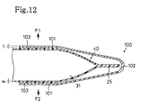
- Figure 11 is a perspective view of the disassembled ink package 40 and plate spring member 100.
- Figure 12 is a partial cross section of the ink package 40 to which the plate spring member 100 is fitted.
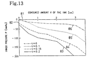
- Figure 13 is a graph showing the relationship between the consumed amount V of ink and the inner pressure P inside the ink sealing portion 31, and comparing ink packages 40 in which the plate spring members 100 have different plate thicknesses t.
- the arrow Y in Fig. 11 shows the direction along which the plate spring member 100 is fitted to the ink package 40.
- the horizontal axis 81 represents the consumed amount V of the ink sealed inside the ink sealing portion 31
- the vertical axis 82 represents the inner pressure P inside the ink sealing portion 31.
- a shape-restoring ability can be provided to the ink package 40 by fitting the plate spring member 100 to the ink package 40.
- the plate spring member 100 is formed into a substantially " ⁇ " shape, viewed from the side, and is made of an elastic material such as a spring steel material.
- the spring plate member 100 has a pair of jointing portions 101 opposite to each other in the vertical direction, and the respective jointing portions 101 are joined to each other through a connector 102.
- an adhesive agent 103 is applied to the opposite faces of the pair of jointing portions 101 of the plate spring 100, and then the plate spring member 100 is slid in the direction of the arrow Y (see Fig. 11) so that the pair of jointing portions 101 sandwich the ink sealing portion 31 of the ink package 40.
- the respective jointing portions 101 of the plate spring member 100 are fitted onto the upper and lower faces of the ink sealing portion 31.
- the plate spring member 100 By fitting the plate spring member 100 to the ink sealing portion 31 of the ink package 40 in the aforementioned manner, a change in the shape of the ink sealing portion 31 of the ink package 40 is restrained. Namely, in the case of extracting the ink from the ink sealing portion 31 with the ink extracting member 22, the ink sealing portion 31 is urged toward the F 1 and F2 directions as indicated with arrows in Fig. 12, with substantially the same strength, by the plate spring member 100, and consequently the portion 31 is not crushed by atmospheric pressure and the like so that the inner pressure P inside the ink sealing portion 31 can be kept within a negative pressure. As a result, in the case of supplying the ink extracted with the ink extracting member 22 into the printer head, the ink supplying pressure for the ink can be kept within a negative pressure.
- the curve 83 solid line
- the curve 84 alternating long and short dashed line
- the curve 85 alternative long and two short dashed line
- the curve 86 represents the ink package 40 not using any plate spring member 100.
- the inner pressure P inside the ink sealing portion 31 drastically decreases in the order of curves 83, 84 and 85, with an increase in the consumed amount V of ink.
- curves 83 - 85 are compared with curve 86, the amount of the inner pressure P, which are each represented by curves 83 - 85, decreased by an increase in the consumed amount V of ink in the ink packages 40 using the plate spring member 100, are more drastically reduced than the amount of the inner pressure P, which is represented by curve 86, decreased by an increase in the consumed amount V of ink in the ink package not using any plate spring member 100.
- the plate thickness t of the plate spring member 100 is larger, the shape-restoring ability of the ink sealing portion 31 is more remarkable and the effect of restraining the change in the shape of the ink sealing portion 31 becomes greater.
- the desktop printer 200 and the desktop printers 1 and 100 of the first and second embodiments use common printer bodies 2. Therefore, the printer 200 can be used as the printer 1 or 100 by substituting the printer cartridge 203 with the printer cartridge 3 or 103 of the first or second embodiment.
- the respective joining members 25 of the respective extracting members 22 are fitted at different positions along the front and rear direction in Fig. 10.
- the penetrating holes 42 of the respective ink cartridges 40 are arranged at the positions corresponding to the position of the respective ink extracting members 22.
- the entire ink package 30 is made of the laminated structure film material, and the ink extracting member 22 is stuck into its recess 32 to extract ink.
- the ink extracting method is not necessarily limited to this.
- ink may be directly sealed into the ink cartridge.
- the portion which the ink extracting member is stuck is formed by melt-joining the laminated structure film material to a part of the ink cartridge, and the ink extracting member may be stuck into the laminated structure film material to extract ink inside the ink cartridge.
- the ink cartridge may be made of a material compatible with the ink used for printing, for example, polyoxymethylene (POM) type resin.
- POM polyoxymethylene
Landscapes
- Ink Jet (AREA)
Claims (18)
- Tintenliefervorrichtung zum Liefern von Tinte, die zum Drucken benutzt wird, zu einem Druckkopf, mit:einer Tintenverpackung, die die Tinte abdichtet, wobei die Tintenverpackung aus einem Filmmaterial hergestellt ist, das eine Formwiederherstellungseigenschaft aufweist, die die Tintenverpackung vom Ändern der Form zurückhält, während die Tinte aus der Tintenverpackung gezogen wird, sodass ein Unterdruck an die zu dem Drucker zu liefernde Tinte angelegt wird;einem Tintenextraktionsteil, das einen nadelartigen Spitzenabschnitt aufweist, der in die Tintenverpackung gesteckt werden kann, wobei das Tintenextraktionsteil Tinte aus der Tintenverpackung extrahieren kann, indem der nadelartige Spitzenabschnitt in die Tintenverpackung gesteckt wird, und die extrahierte Tinte in den Druckkopf liefern kann.
- Tintenliefervorrichtung nach Anspruch 1,
bei der das Tintenextraktionsteil einen äußeren Durchmesser aufweist der nicht größer als ungefähr 5mm ist. - Tintenverpackung zum Liefern von Tinte zum Drucken zu einem Druckkopf, mit:einer Tintenverpackung, die aus einem Filmmaterial hergestellt ist, das eine Formwiederherstellungseigenschaft aufweist, die die Tintenverpackung vom Ändern der Form zurückhält, während die Tinte aus der Tintenverpackung gezogen wird, sodass ein Unterdruck an die zu dem Druckkopf zu liefernde Tinte angelegt wird.
- Tintenpatrone mit:einer Tintenverpackung, die aus einem Filmmaterial hergestellt ist, das eine Formwiederherstellungseigenschaft aufweist, die die Tintenverpackung vom Ändern der Form zurückhält, während Tinte aus der Tintenverpackung gezogen wird, sodass ein Unterdruck an die zu dem Druckkopf zu liefernde Tinte angelegt wird;einem Patronengehäuse, das die Tintenverpackung aufnimmt, wobei das Patronengehäuse aus einem starren Material hergestellt ist und ein Eindringungsloch definiert; undeinem Abdichtteil, das das Eindringungsloch abdeckt und das Patronengehäuse als luftdicht aufrechterhält.
- Tintenliefervorrichtung nach Anspruch 1 oder 2 oder Tintenverpackung nach Anspruch 3 oder Tintenpatrone nach Anspruch 4, worin die Tintenverpackung eine laminierte Struktur aufweist, bei der eine Mehrzahl von Filmblättern, die aus Polyethylenharz gebildet sind, laminiert sind.
- Tintenliefervorrichtung, Verpackung oder Patrone nach einem der vorhergehenden Ansprüche, worin das die Tintenverpackung bildende Material eine Dicke von ungefähr 30µm bis 300µm aufweist.
- Tintenliefervorrichtung, Verpackung oder Patrone nach einem der vorhergehenden Ansprüche, worin die Tintenverpackung einen Tintenabdichtabschnitt aufweist, der die Tinte abdichtet, und eine longitudinale Länge des Tintenabdichtabschnittes ungefähr zweimal oder weniger solang wie eine laterale Länge des Tintenabdichtabschnittes ist.
- Tintenliefervorrichtung, Verpackung oder Patrone nach einem der vorhergehenden Ansprüche, worin die Tintenverpackung einen Tintenabdichtabschnitt aufweist, der die Tinte abdichtet, und mindestens eine einer longitudinalen Länge und einer lateralen Länge des Tintenabdichtabschnittes ungefähr 100mm oder weniger ist.
- Tintenliefervorrichtung, Verpackung oder Patrone nach einem der vorhergehenden Ansprüche, worin die Tintenverpackung einen Abdichtabschnitt aufweist, der die Tinte abdichtet, und mindestens ein Abschnitt einer äußeren Oberfläche des Tintenabdichtabschnittes in mindestens eine einer im Wesentlichen ebenen Form und im Wesentlichen einer konkaven Form gebildet ist.
- Tintenliefervorrichtung, Verpackung oder Patrone nach Anspruch 9, worin beide Seiten des Filmmateriales schmelzverbunden sind, wodurch der Abschnitt der äußeren Oberfläche des Tintenabdichtabschnittes, der in die im Wesentlichen eine einer im Wesentlichen ebenen Form und einer im Wesentlichen konkaven Form gebildet ist, auf einer Fläche hergestellt ist, die beide der schmelzverbundenen Seiten kreuzt.
- Tintenliefervorrichtung, Verpackung oder Patrone nach einem der vorhergehenden Ansprüche, worin die Tintenverpackung ein Verformungszurückhaltungsteil enthält, das an die Tintenverpackung zum Zurückhalten der Verformung der Tintenverpackung gepasst ist.
- Tintenliefervorrichtung zum Liefern von Tinte, die zum Drucken benutzt wird, zu einem Druckkopf, mit:einer Tintenverpackung, die Tinte zum Drucken zu dem Druckkopf liefert, wobei die Tintenverpackung eine obere Verpackung und eine untere Verpackung , die unterhalb der oberen Verpackung vorgesehen ist, enthält zum Abdichten der Tinte, wobei die obere Verpackung eine Formwiederherstellungsfähigkeit aufweist, die die Tintenverpackung vom Ändern der Form zurückhält, während die Tinte aus der Tintenverpackung gezogen wird, sodass ein Unterdruck an die zu dem Druckkopf zu liefernde Tinte angelegt wird;einem Tintenextraktionsteil, das einen nadelartigen Spitzenabschnitt enthält, der in die Tintenverpackung gesteckt werden kann, wobei das Tintenextraktionsteil die Tinte aus der Tintenverpackung extrahieren kann, indem der nadelartige Spitzenabschnitt in die Tintenverpackung gesteckt wird, und die extrahierte Tinte in den Druckkopf liefern kann.
- Tintenliefervorrichtung nach Anspruch 12, weiter mit einer Tintenpatrone, die ein Eindringungsloch definiert, wobei das Eindringungsloch an einer Position entsprechend dem Tintenextraktionsteil definiert ist.
- Tintenliefervorrichtung nach Anspruch 12 oder 13, bei der die obere Verpackung und die untere Verpackung aus einem Filmmaterial mit einer Formwiederherstellungsfähigkeit hergestellt sind;
die Formwiederherstellungsfähigkeit des Filmmateriales, das die obere Verpackung bildet, größer als die Formwiederherstellungsfähigkeit des Filmmateriales ist, das die untere Verpackung bildet. - Tintenliefervorrichtung nach Anspruch 12, 13 oder 14, bei der die Tintenverpackung ein Verformungszurückhaltungsteil enthält, das an mindestens eine der oberen Verpackung und der unteren Verpackung gepasst ist, zum Zurückhalten der Verformung der Tintenverpackung, wobei die andere der oberen Verpackung und der unteren Verpackung aus einem Filmmaterial hergestellt ist, das eine Formwiederherstellungsfähigkeit aufweist; das Filmmaterial, das mindestens eine der oberen Verpackung und dem Verformungszurückhaltungsteil, das an die obere Verpackung gepasst ist, bildet, starrer als das Verformungszurückhaltungsteil, das an mindestens einer der unteren Verpackung gepasst ist, und des Filmmateriales, das die untere Verpackung bildet, ist.
- Tintenverpackungssystem zum Liefern von Tinte zum Drucken an einen Druckkopf, mit:einer oberen Verpackung mit einer Formwiederherstellungsfähigkeit, die die Tintenverpackung vom Ändern der Form zurückhält, während Tinte aus der Tintenverpackung gezogen wird, sodass ein Unterdruck an die zu dem Druckkopf zu liefernde Tinte angelegt wird; undeiner unteren Verpackung, die unter der oberen Verpackung vorgesehen ist, sodass die Tinte abgedichtet ist.
- Tintenverpackungssystem nach Anspruch 16, bei der die obere Verpackung und die untere Verpackung aus einem Filmmaterial mit einer Formwiederherstellungsfähigkeit hergestellt sind;
die Formwiederherstellungsfähigheit des Filmmateriales, das die obere Verpackung bildet, größer als die Formwiederherstellungsfähigkeit des Filmmateriales ist, das die untere Verpackung bildet. - Tintenverpackungssystem nach Anspruch 16 oder 17, bei dem die Tintenverpackung ein Verformungszurückhaltungsteil enthält, das an mindestens eine der oberen Verpackung und der unteren Verpackung gepasst ist zum Zurückhalten der Verformung der mindestens einen der oberen Verpackung und der unteren Verpackung, wobei die andere der mindestens einen der oberen Verpackung und der unteren Verpackung aus dem Filmmaterial mit der Formwiederherstellungsfähigkeit hergestellt ist;
das Filmmaterial zum Bilden von mindestens einer der oberen Verpackung und des Verformungszurückhaltungsteiles, das an die obere Verpackung gepasst ist, starrer ist als das Verformungszurückhaltungsteil, das an mindestens eine der unteren Verpackung und des Filmmateriales gepasst ist, das die untere Verpackung bildet.
Applications Claiming Priority (6)
| Application Number | Priority Date | Filing Date | Title |
|---|---|---|---|
| JP26142997 | 1997-09-26 | ||
| JP26146397 | 1997-09-26 | ||
| JP26146397A JP4013295B2 (ja) | 1997-09-26 | 1997-09-26 | プリンタ |
| JP261463/97 | 1997-09-26 | ||
| JP26142997A JPH1199655A (ja) | 1997-09-26 | 1997-09-26 | インク供給装置 |
| JP261429/97 | 1997-09-26 |
Publications (3)
| Publication Number | Publication Date |
|---|---|
| EP0904940A2 EP0904940A2 (de) | 1999-03-31 |
| EP0904940A3 EP0904940A3 (de) | 2000-11-02 |
| EP0904940B1 true EP0904940B1 (de) | 2007-01-03 |
Family
ID=26545064
Family Applications (1)
| Application Number | Title | Priority Date | Filing Date |
|---|---|---|---|
| EP98307391A Expired - Lifetime EP0904940B1 (de) | 1997-09-26 | 1998-09-11 | Tintenversorgungsvorrichtung |
Country Status (3)
| Country | Link |
|---|---|
| US (1) | US6276787B1 (de) |
| EP (1) | EP0904940B1 (de) |
| DE (1) | DE69836784T2 (de) |
Families Citing this family (30)
| Publication number | Priority date | Publication date | Assignee | Title |
|---|---|---|---|---|
| US6505924B2 (en) * | 1998-09-30 | 2003-01-14 | Brother Kogyo Kabushiki Kaisha | Ink cartridge |
| AU1072001A (en) * | 1999-09-30 | 2001-04-30 | Kimberly-Clark Worldwide, Inc. | Printhead ink delivery apparatus and method to increase the ink delivery pressure on a printhead utilizing said apparatus |
| US6464346B2 (en) | 1999-10-29 | 2002-10-15 | Hewlett-Packard Company | Ink containment and delivery techniques |
| EP1120258B1 (de) | 2000-01-21 | 2006-05-17 | Seiko Epson Corporation | Tintenpatrone und Tintenstrahldruckvorrichtung mit einer derartigen Tintenpatrone |
| ATE324986T1 (de) * | 2000-03-27 | 2006-06-15 | Seiko Epson Corp | Tintenstrahldrucker |
| US7438400B2 (en) * | 2003-07-16 | 2008-10-21 | Seiko Epson Corporation | Liquid container, liquid ejecting device, and method of checking arrangement of liquid storing packs |
| US7594328B2 (en) * | 2003-10-03 | 2009-09-29 | Hewlett-Packard Development Company, L.P. | Method of forming a slotted substrate with partially patterned layers |
| US7374355B2 (en) | 2004-01-21 | 2008-05-20 | Silverbrook Research Pty Ltd | Inkjet printer cradle for receiving a pagewidth printhead cartridge |
| US20050157128A1 (en) * | 2004-01-21 | 2005-07-21 | Silverbrook Research Pty Ltd | Pagewidth inkjet printer cartridge with end electrical connectors |
| US7524016B2 (en) * | 2004-01-21 | 2009-04-28 | Silverbrook Research Pty Ltd | Cartridge unit having negatively pressurized ink storage |
| US7367647B2 (en) * | 2004-01-21 | 2008-05-06 | Silverbrook Research Pty Ltd | Pagewidth inkjet printer cartridge with ink delivery member |
| US7328985B2 (en) * | 2004-01-21 | 2008-02-12 | Silverbrook Research Pty Ltd | Inkjet printer cartridge refill dispenser with security mechanism |
| US7364264B2 (en) * | 2004-01-21 | 2008-04-29 | Silverbrook Research Pty Ltd | Inkjet printer cradle with single drive motor performing multiple functions |
| US7441865B2 (en) | 2004-01-21 | 2008-10-28 | Silverbrook Research Pty Ltd | Printhead chip having longitudinal ink supply channels |
| US7645025B2 (en) * | 2004-01-21 | 2010-01-12 | Silverbrook Research Pty Ltd | Inkjet printer cartridge with two printhead integrated circuits |
| US7198352B2 (en) * | 2004-01-21 | 2007-04-03 | Kia Silverbrook | Inkjet printer cradle with cartridge stabilizing mechanism |
| US7448734B2 (en) | 2004-01-21 | 2008-11-11 | Silverbrook Research Pty Ltd | Inkjet printer cartridge with pagewidth printhead |
| US7469989B2 (en) | 2004-01-21 | 2008-12-30 | Silverbrook Research Pty Ltd | Printhead chip having longitudinal ink supply channels interrupted by transverse bridges |
| US7083273B2 (en) * | 2004-01-21 | 2006-08-01 | Silverbrook Research Pty Ltd | Inkjet printer cartridge with uniform compressed air distribution |
| US7731327B2 (en) | 2004-01-21 | 2010-06-08 | Silverbrook Research Pty Ltd | Desktop printer with cartridge incorporating printhead integrated circuit |
| US20050157112A1 (en) * | 2004-01-21 | 2005-07-21 | Silverbrook Research Pty Ltd | Inkjet printer cradle with shaped recess for receiving a printer cartridge |
| US7360868B2 (en) * | 2004-01-21 | 2008-04-22 | Silverbrook Research Pty Ltd | Inkjet printer cartridge with infrared ink delivery capabilities |
| US20050157125A1 (en) * | 2004-01-21 | 2005-07-21 | Silverbrook Research Pty Ltd | Inkjet printer cartridge with integral shield |
| US7097291B2 (en) | 2004-01-21 | 2006-08-29 | Silverbrook Research Pty Ltd | Inkjet printer cartridge with ink refill port having multiple ink couplings |
| US7303255B2 (en) | 2004-01-21 | 2007-12-04 | Silverbrook Research Pty Ltd | Inkjet printer cartridge with a compressed air port |
| US20050157000A1 (en) * | 2004-01-21 | 2005-07-21 | Silverbrook Research Pty Ltd | Inkjet printer cradle with end data and power contacts |
| JP2008087193A (ja) * | 2006-09-29 | 2008-04-17 | Brother Ind Ltd | インクジェットプリンタ |
| JP5455755B2 (ja) * | 2009-06-08 | 2014-03-26 | 株式会社セイコーアイ・インフォテック | インクジェット記録装置 |
| JP6042177B2 (ja) * | 2012-11-14 | 2016-12-14 | 株式会社ミマキエンジニアリング | インクパック |
| CN110154531B (zh) * | 2019-06-28 | 2020-08-18 | 邓权塑业科技(湖南)有限公司 | 一种提高喷印稳定性的喷印装置 |
Family Cites Families (12)
| Publication number | Priority date | Publication date | Assignee | Title |
|---|---|---|---|---|
| JPS5734990A (en) | 1980-08-12 | 1982-02-25 | Canon Inc | Apparatus for detecting ink residual amount |
| US4374521A (en) * | 1980-09-12 | 1983-02-22 | Puritan-Bennett Corporation | Squeeze bag type resuscitator apparatus |
| JPH0698774B2 (ja) * | 1984-02-09 | 1994-12-07 | キヤノン株式会社 | インク容器 |
| US5040001A (en) * | 1990-06-27 | 1991-08-13 | Hewlett-Packard Company | Collapsible storage bladder for ink cartridges |
| JP2752793B2 (ja) | 1990-12-10 | 1998-05-18 | キヤノン株式会社 | インクジェット記録装置および該装置用インクタンクカートリッジ |
| EP0715958B1 (de) | 1991-05-27 | 1998-08-12 | Seiko Epson Corporation | Tintenkassette für Tintenstrahlaufzeichnungsvorrichtung |
| ATE161478T1 (de) * | 1992-03-13 | 1998-01-15 | Canon Kk | Tintenbehälter |
| US5574489A (en) | 1994-03-30 | 1996-11-12 | Hewlett-Packard Company | Ink cartridge system for ink-jet printer |
| US5691755A (en) * | 1994-04-18 | 1997-11-25 | Hewlett-Packard Company | Collapsible ink cartridge |
| JP3245082B2 (ja) | 1996-02-23 | 2002-01-07 | キヤノン株式会社 | 液体収納容器、該容器の製造方法、該容器を用いるインクジェットカートリッジ及びインクジェット記録装置 |
| US5988802A (en) | 1996-08-30 | 1999-11-23 | Hewlett-Packard Company | Off-axis ink supply with pressurized ink tube for preventing air ingestion |
| US5971533A (en) | 1997-01-07 | 1999-10-26 | Brother Kogyo Kabushiki Kaisha | Ink cartridge and printer |
-
1998
- 1998-08-11 US US09/132,486 patent/US6276787B1/en not_active Expired - Lifetime
- 1998-09-11 DE DE69836784T patent/DE69836784T2/de not_active Expired - Lifetime
- 1998-09-11 EP EP98307391A patent/EP0904940B1/de not_active Expired - Lifetime
Also Published As
| Publication number | Publication date |
|---|---|
| DE69836784D1 (de) | 2007-02-15 |
| DE69836784T2 (de) | 2007-11-08 |
| EP0904940A3 (de) | 2000-11-02 |
| EP0904940A2 (de) | 1999-03-31 |
| US6276787B1 (en) | 2001-08-21 |
Similar Documents
| Publication | Publication Date | Title |
|---|---|---|
| EP0904940B1 (de) | Tintenversorgungsvorrichtung | |
| EP2292431B1 (de) | Flüssigkeitsbehälter, Verfahren zur Montage und Demontage des Flüssigkeitsbehälters und Bilderzeugungsvorrichtung | |
| US6739707B2 (en) | Ink cartridge | |
| US5602574A (en) | Matrix pen arrangement for inkjet printing | |
| US5988801A (en) | High performance tubing for inkjet printing systems with off-board ink supply | |
| KR100486804B1 (ko) | 잉크 제트 인쇄 장치 및 잉크 공급 방법 | |
| EP2204288B1 (de) | Tintenkartusche und Bildformungsvorrichtung mit der Tintenkartusche | |
| KR20020096957A (ko) | 잉크 제트 인쇄 장치 및 잉크 공급 방법 | |
| US20030218660A1 (en) | Liquid supplying tube in use for liquid jet device and liquid jet device provided with the same | |
| JP4207217B2 (ja) | 印刷装置 | |
| US20060221120A1 (en) | Cap Members and Liquid Ejecting Devices Comprising Cap Members | |
| US20090278900A1 (en) | Ink jet printing apparatus and ink tank for the same | |
| US7425059B2 (en) | Ink container, inkjet printing head, and inkjet printing apparatus | |
| JP2001322292A (ja) | インクジェットプリンタ及びそのヘッドカートリッジ | |
| JP2000103079A (ja) | インクカートリッジ | |
| JP4013295B2 (ja) | プリンタ | |
| JP2002127546A (ja) | インクジェットプリンタ | |
| JP2001301199A (ja) | インクジェットプリンタ及びそのヘッドカートリッジ | |
| JPH1199659A (ja) | インクカートリッジ | |
| JP4688189B2 (ja) | 液体供給装置及び画像形成装置 | |
| JP2005319587A (ja) | 液体収能容器、インクジェット記録装置、及び画像形成装置 | |
| JP2003094679A (ja) | インクジェットヘッドユニット及びこれを具備したインクジェット式記録装置 | |
| JP4609087B2 (ja) | バルブユニット及び同バルブユニットを備えた液体噴射装置 | |
| JPH1199655A (ja) | インク供給装置 | |
| JPH1199661A (ja) | インク供給装置 |
Legal Events
| Date | Code | Title | Description |
|---|---|---|---|
| PUAI | Public reference made under article 153(3) epc to a published international application that has entered the european phase |
Free format text: ORIGINAL CODE: 0009012 |
|
| AK | Designated contracting states |
Kind code of ref document: A2 Designated state(s): DE FR GB NL |
|
| AX | Request for extension of the european patent |
Free format text: AL;LT;LV;MK;RO;SI |
|
| PUAL | Search report despatched |
Free format text: ORIGINAL CODE: 0009013 |
|
| AK | Designated contracting states |
Kind code of ref document: A3 Designated state(s): AT BE CH CY DE DK ES FI FR GB GR IE IT LI LU MC NL PT SE |
|
| AX | Request for extension of the european patent |
Free format text: AL;LT;LV;MK;RO;SI |
|
| 17P | Request for examination filed |
Effective date: 20010417 |
|
| AKX | Designation fees paid |
Free format text: DE FR GB NL |
|
| GRAP | Despatch of communication of intention to grant a patent |
Free format text: ORIGINAL CODE: EPIDOSNIGR1 |
|
| GRAS | Grant fee paid |
Free format text: ORIGINAL CODE: EPIDOSNIGR3 |
|
| GRAA | (expected) grant |
Free format text: ORIGINAL CODE: 0009210 |
|
| AK | Designated contracting states |
Kind code of ref document: B1 Designated state(s): DE FR GB NL |
|
| PG25 | Lapsed in a contracting state [announced via postgrant information from national office to epo] |
Ref country code: NL Free format text: LAPSE BECAUSE OF FAILURE TO SUBMIT A TRANSLATION OF THE DESCRIPTION OR TO PAY THE FEE WITHIN THE PRESCRIBED TIME-LIMIT Effective date: 20070103 |
|
| REG | Reference to a national code |
Ref country code: GB Ref legal event code: FG4D |
|
| REF | Corresponds to: |
Ref document number: 69836784 Country of ref document: DE Date of ref document: 20070215 Kind code of ref document: P |
|
| ET | Fr: translation filed | ||
| NLV1 | Nl: lapsed or annulled due to failure to fulfill the requirements of art. 29p and 29m of the patents act | ||
| PLBE | No opposition filed within time limit |
Free format text: ORIGINAL CODE: 0009261 |
|
| STAA | Information on the status of an ep patent application or granted ep patent |
Free format text: STATUS: NO OPPOSITION FILED WITHIN TIME LIMIT |
|
| 26N | No opposition filed |
Effective date: 20071005 |
|
| REG | Reference to a national code |
Ref country code: FR Ref legal event code: PLFP Year of fee payment: 19 |
|
| PGFP | Annual fee paid to national office [announced via postgrant information from national office to epo] |
Ref country code: GB Payment date: 20160830 Year of fee payment: 19 |
|
| PGFP | Annual fee paid to national office [announced via postgrant information from national office to epo] |
Ref country code: FR Payment date: 20160817 Year of fee payment: 19 |
|
| PGFP | Annual fee paid to national office [announced via postgrant information from national office to epo] |
Ref country code: DE Payment date: 20160928 Year of fee payment: 19 |
|
| REG | Reference to a national code |
Ref country code: DE Ref legal event code: R119 Ref document number: 69836784 Country of ref document: DE |
|
| GBPC | Gb: european patent ceased through non-payment of renewal fee |
Effective date: 20170911 |
|
| REG | Reference to a national code |
Ref country code: FR Ref legal event code: ST Effective date: 20180531 |
|
| PG25 | Lapsed in a contracting state [announced via postgrant information from national office to epo] |
Ref country code: DE Free format text: LAPSE BECAUSE OF NON-PAYMENT OF DUE FEES Effective date: 20180404 Ref country code: GB Free format text: LAPSE BECAUSE OF NON-PAYMENT OF DUE FEES Effective date: 20170911 |
|
| PG25 | Lapsed in a contracting state [announced via postgrant information from national office to epo] |
Ref country code: FR Free format text: LAPSE BECAUSE OF NON-PAYMENT OF DUE FEES Effective date: 20171002 |