EP0904846B1 - Handabschaltpistole für Hochdruckreinigungsgeräte mit Sicherungseinrichtung zum Schutz vor Ablösen des Sprührohrs - Google Patents
Handabschaltpistole für Hochdruckreinigungsgeräte mit Sicherungseinrichtung zum Schutz vor Ablösen des Sprührohrs Download PDFInfo
- Publication number
- EP0904846B1 EP0904846B1 EP98118285A EP98118285A EP0904846B1 EP 0904846 B1 EP0904846 B1 EP 0904846B1 EP 98118285 A EP98118285 A EP 98118285A EP 98118285 A EP98118285 A EP 98118285A EP 0904846 B1 EP0904846 B1 EP 0904846B1
- Authority
- EP
- European Patent Office
- Prior art keywords
- safety device
- spray tube
- gun
- inner part
- fastening nut
- Prior art date
- Legal status (The legal status is an assumption and is not a legal conclusion. Google has not performed a legal analysis and makes no representation as to the accuracy of the status listed.)
- Expired - Lifetime
Links
- 239000007921 spray Substances 0.000 title claims abstract description 21
- 238000004140 cleaning Methods 0.000 title 1
- 210000002445 nipple Anatomy 0.000 claims description 10
- 239000000463 material Substances 0.000 claims description 4
- 239000007769 metal material Substances 0.000 claims 1
- 238000013459 approach Methods 0.000 description 6
- 230000006835 compression Effects 0.000 description 2
- 238000007906 compression Methods 0.000 description 2
- 210000003746 feather Anatomy 0.000 description 2
- 230000001419 dependent effect Effects 0.000 description 1
- 238000005553 drilling Methods 0.000 description 1
- 210000004907 gland Anatomy 0.000 description 1
- 230000000750 progressive effect Effects 0.000 description 1
- 238000007789 sealing Methods 0.000 description 1
- XLYOFNOQVPJJNP-UHFFFAOYSA-N water Substances O XLYOFNOQVPJJNP-UHFFFAOYSA-N 0.000 description 1
Images

Classifications
-
- B—PERFORMING OPERATIONS; TRANSPORTING
- B05—SPRAYING OR ATOMISING IN GENERAL; APPLYING FLUENT MATERIALS TO SURFACES, IN GENERAL
- B05B—SPRAYING APPARATUS; ATOMISING APPARATUS; NOZZLES
- B05B15/00—Details of spraying plant or spraying apparatus not otherwise provided for; Accessories
- B05B15/60—Arrangements for mounting, supporting or holding spraying apparatus
- B05B15/65—Mounting arrangements for fluid connection of the spraying apparatus or its outlets to flow conduits
- B05B15/652—Mounting arrangements for fluid connection of the spraying apparatus or its outlets to flow conduits whereby the jet can be oriented
Definitions
- the present invention is a Handabschaltpistole according to The preamble of claim 1, as for example from DE-A-44 28 634 is known.
- Object of the present invention is therefore a Handabschaltpistole of mentioned type in such a way that they are reliable and also easier to handle.
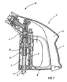
- FIG. 1 schematically shows a cross section through a manual shut-off pistol 1 according to FIG of the invention.
- the handshake gun 1 has two substantially mirror-symmetrical to one another and appropriately arranged Housing shells 5 on. In the figure, only one of these housing shells 5 shown.
- the two shells 5 define a closed housing, the one Front wall 6, a rear wall 7, a bottom wall 8 and an end wall 9 has.
- the high-pressure medium is supplied via a high-pressure hose 4 through a receiving opening 3 of a buckling protection sleeve 2 in the manual shutdown pistol entry.
- the high pressure hose 4 is on a neck of a nipple 10 with a compression sleeve 11 is sealingly held.
- the high-pressure medium is then through the manual shutdown gun 1 a spray tube 16 supplied.
- the corresponding terminal 12 is shown in Figure 2 and in the modified embodiment shown in Figure 3.
- a valve housing 13 is provided with the an inner bore 14 is provided with a conical end 15.
- the spray tube 16 is screwed into a nipple 17, which in turn from a Fixing nut, consisting of an outer part 18 and an inner part 19th is overruled.
- the nipple 17 in this case has a projection 26, to which a corresponding Approach 29 of the inner part 19 can create.
- a seal 27 For sealing in the bore 14 is a seal 27, preferably an O-ring provided.
- the fastening nut consisting of the components 18, 19, is preferably made of two made of separate materials.
- the inner part 19 is preferably a metallic one Material, which then with a plastic material to form the outer part 18th is overmoulded.
- the contact surface between the outer part 18 and the inner part 19th Can be wavy, jagged or otherwise to increase adhesion be educated.
- the inner part 19 is provided with an internal thread, which is an external thread on the valve housing 13 corresponds. Accordingly, the inner part 19 with the help of the outer part 18 are screwed.
Landscapes
- Nozzles (AREA)
- Cleaning By Liquid Or Steam (AREA)
- Details Or Accessories Of Spraying Plant Or Apparatus (AREA)
Description
- Figur 1 :
- einen Querschnitt durch eine Handabschaltpistole mit Arretiereinrichtung;
- Figur 2:
- eine vergrößerte Einzelheit aus Figur 1.
- 1.
- Handabschaltpistole
- 2.
- Knickschutzhülse
- 3.
- Aufnahmeöffnung
- 4.
- HD-Schlauch
- 5.
- Gehäuseschale
- 6.
- Vorderwand
- 7.
- Rückwand
- 8.
- Bodenwand
- 9.
- Stirnwand
- 10.
- Einpreßnippel
- 11.
- Preßhülse
- 12.
- Anschluß, 12a
- 13.
- Ventilgehäuse
- 14.
- Bohrung
- 15.
- Konus
- 16.
- Sprührohr
- 17.
- Nippel
- 18.
- Außenteil
- 19.
- Innenteil
- 20.
- Indexierbohrung
- 21.
- Stift
- 22.
- Ausnehmung
- 23.
- Feder
- 24.
- Pfeilrichtung
- 25.
- Pfeilrichtung
- 26.
- Ansatz
- 27.
- Dichtung
- 29.
- Ansatz
- 30.
- Feder
- 31.
- Pfeilrichtung
- 32.
- Pfeilrichtung
Claims (4)
- Handabschaltpistole für Hochdruckreinigungsgeräte mit einem Gehäuse, an dem ein Sprührohr drehbar angebracht ist und mit einer Sicherungseinrichtung zum Schutz vor Ablösen des Sprührohrs, wobei die Sicherungseinrichtung das Verdrehen des Sprührohres (16) gegenüber dem Gehäuse (5) während des Betriebs um eine Verdrehung über 360° hinaus verhindert,
dadurch gekennzeichnet, daß
die Sicherungseinrichtung eine Befestigungsmutter (18,19) aufweist, die einen Nippel (26) des Sprührohres (16) übergreift und auf ein im Gehäuse (5) angeordnetes Ventilgehäuse (13) aufgeschraubt ist und daß der Sicherungseinrichtung ein federbelastet verschiebbarer Stift (21) am Gehäuse (5) zugeordnet ist, der zur Verdrehsicherung zwischen der Befestigungsmutter (18,19) und dem Ventilgehäuse (13) in Indexbohrungen der Befestigungsmutter (18,19) eingreifbar ist. - Handabschaltpistole nach Anspruch 1, dadurch gekennzeichnet, daß die Befestigungsmutter aus einem Außenteil (18) und einem Innenteil (19) besteht.
- Handabschaltpistole nach Anspruch 2, dadurch gekennzeichnet, daß das Außenteil (18) aus einem Plastikmaterial und das Innenteil (19) aus einem metallischen Werkstoff besteht und das Außenteil (18) auf das Innenteil (19) umspritzt ist.
- Handabschaltpistole nach Anspruch 3, dadurch gekennzeichnet, daß die Berührfläche zwischen dem Außenteil (18) und dem Innenteil (19) zur Erhöhung der Haftung wellenförmig oder gezackt ist.
Applications Claiming Priority (2)
| Application Number | Priority Date | Filing Date | Title |
|---|---|---|---|
| DE19743032 | 1997-09-30 | ||
| DE19743032A DE19743032A1 (de) | 1997-09-30 | 1997-09-30 | Handabschaltpistole mit verdrehbarem und feststellbarem Sprührohr |
Publications (3)
| Publication Number | Publication Date |
|---|---|
| EP0904846A2 EP0904846A2 (de) | 1999-03-31 |
| EP0904846A3 EP0904846A3 (de) | 2002-01-23 |
| EP0904846B1 true EP0904846B1 (de) | 2005-08-10 |
Family
ID=7844026
Family Applications (1)
| Application Number | Title | Priority Date | Filing Date |
|---|---|---|---|
| EP98118285A Expired - Lifetime EP0904846B1 (de) | 1997-09-30 | 1998-09-28 | Handabschaltpistole für Hochdruckreinigungsgeräte mit Sicherungseinrichtung zum Schutz vor Ablösen des Sprührohrs |
Country Status (4)
| Country | Link |
|---|---|
| EP (1) | EP0904846B1 (de) |
| AT (1) | ATE301504T1 (de) |
| DE (2) | DE19743032A1 (de) |
| DK (1) | DK0904846T3 (de) |
Families Citing this family (1)
| Publication number | Priority date | Publication date | Assignee | Title |
|---|---|---|---|---|
| DE102008059589A1 (de) | 2008-11-28 | 2010-06-02 | Nilfisk-Advance A/S | Handabschaltpistole |
Family Cites Families (9)
| Publication number | Priority date | Publication date | Assignee | Title |
|---|---|---|---|---|
| DE822065C (de) * | 1949-07-28 | 1951-11-22 | Josef Freiherr | Spritzpistole zum Aufbringen von Farben auf Decken und Waende |
| JPS5652629B2 (de) * | 1973-10-11 | 1981-12-14 | ||
| DE2531969A1 (de) * | 1975-07-17 | 1977-03-17 | Theo Krebs Gmbh | Spritzduese zum zerstaeuben von fluessigkeiten, hauptsaechlich farben und lacke, in form eines flachstrahles |
| DE3337980C1 (de) * | 1983-10-19 | 1985-05-09 | Daimler-Benz Ag, 7000 Stuttgart | Einrichtung zum schnellen Wechseln von Spruehduesen zum Aufspruehen von Korrosionsschutzmittel in Karosseriehohlraeume |
| DE3720241C2 (de) * | 1986-09-26 | 1994-09-22 | Wolfgang Suttner | Ventilpistole für ein Hochdruckreinigungsgerät |
| CH677076A5 (de) * | 1989-04-27 | 1991-04-15 | Edi Mark | |
| DD290596A5 (de) * | 1989-12-22 | 1991-06-06 | Tu "Otto Von Guericke",De | Duesenkupplung |
| DE4416939A1 (de) * | 1994-05-13 | 1995-11-16 | Bruno Jesswein Kunststofftechn | Spritzpistole |
| DE4428634C2 (de) * | 1994-08-12 | 1998-03-26 | Bib Becker Industrieberatung G | Spritzpistole mit einem Griffstück und einem betätigbaren Ventilstößel |
-
1997
- 1997-09-30 DE DE19743032A patent/DE19743032A1/de not_active Ceased
-
1998
- 1998-09-28 DE DE59812986T patent/DE59812986D1/de not_active Expired - Lifetime
- 1998-09-28 EP EP98118285A patent/EP0904846B1/de not_active Expired - Lifetime
- 1998-09-28 AT AT98118285T patent/ATE301504T1/de not_active IP Right Cessation
- 1998-09-28 DK DK98118285T patent/DK0904846T3/da active
Also Published As
| Publication number | Publication date |
|---|---|
| DK0904846T3 (da) | 2005-11-07 |
| EP0904846A3 (de) | 2002-01-23 |
| DE19743032A1 (de) | 1999-04-22 |
| EP0904846A2 (de) | 1999-03-31 |
| DE59812986D1 (de) | 2005-09-15 |
| ATE301504T1 (de) | 2005-08-15 |
Similar Documents
| Publication | Publication Date | Title |
|---|---|---|
| DE69602233T2 (de) | Anbohr-Anschlussstück | |
| EP1355100B1 (de) | Steckkupplung für fluidische Systeme | |
| DE3905722C2 (de) | ||
| DE2138103C3 (de) | Schnellkupplung für Flüssigkeitsund Gasleitungen | |
| EP0803676B1 (de) | Schnellkupplung für die Verbindung von Schlauch- und Rohrleitungen | |
| DE1775302B2 (de) | Schlauchkupplung | |
| DE3720241A1 (de) | Ventilpistole fuer ein hochdruckreinigungsgeraet | |
| DE60204287T2 (de) | Kupplung zur verbindung eines rohrs oder schlauchs durch einschieben | |
| EP0964493B1 (de) | Winkelförmige Leitungseinführung mit einer Trennstelle zwischen den beiden Schenkeln | |
| DE2901266C2 (de) | Wanddurchführung für Kabel, Leitungen, Rohre od.dgl. | |
| DE2539456A1 (de) | Anschlusstueck fuer elektrische leitungen | |
| DE3627274A1 (de) | Schlaucheinband | |
| EP0904846B1 (de) | Handabschaltpistole für Hochdruckreinigungsgeräte mit Sicherungseinrichtung zum Schutz vor Ablösen des Sprührohrs | |
| DE3128541C2 (de) | ||
| DE19923957C2 (de) | Klemmvorrichtung für eine Handluftpumpe | |
| DE3241677C1 (de) | Betaetigungsaufsatz fuer einen Druck-Zugschalter | |
| EP2208676B1 (de) | Rohrklemme | |
| EP0804970B1 (de) | Handspritzpistole für ein Hochdruckreinigungsgerät | |
| EP1832794B1 (de) | Rohrkupplung | |
| EP0833092B1 (de) | Schlauchverbindung und Verfahren zur Montage der Schlauchverbindung | |
| EP0884019B1 (de) | Staubsaugerschlauch mit elektrischen Leitern | |
| WO2009030250A1 (de) | Rohrkupplung | |
| DE897027C (de) | Kupplungsvorrichtung fuer Schlaeuche | |
| DE3106985C2 (de) | Schlauchbefestigung | |
| DE10330142B3 (de) | Setzgerät |
Legal Events
| Date | Code | Title | Description |
|---|---|---|---|
| PUAI | Public reference made under article 153(3) epc to a published international application that has entered the european phase |
Free format text: ORIGINAL CODE: 0009012 |
|
| AK | Designated contracting states |
Kind code of ref document: A2 Designated state(s): AT BE CH CY DE DK ES FI FR GB GR IE IT LI LU MC NL PT SE Kind code of ref document: A2 Designated state(s): AT CH DE DK ES FR GB IT LI NL |
|
| AX | Request for extension of the european patent |
Free format text: AL;LT;LV;MK;RO;SI |
|
| PUAL | Search report despatched |
Free format text: ORIGINAL CODE: 0009013 |
|
| AK | Designated contracting states |
Kind code of ref document: A3 Designated state(s): AT BE CH CY DE DK ES FI FR GB GR IE IT LI LU MC NL PT SE |
|
| AX | Request for extension of the european patent |
Free format text: AL;LT;LV;MK;RO;SI |
|
| 17P | Request for examination filed |
Effective date: 20020705 |
|
| AKX | Designation fees paid |
Free format text: AT CH DE DK ES FR GB IT LI NL |
|
| 17Q | First examination report despatched |
Effective date: 20030221 |
|
| GRAP | Despatch of communication of intention to grant a patent |
Free format text: ORIGINAL CODE: EPIDOSNIGR1 |
|
| GRAS | Grant fee paid |
Free format text: ORIGINAL CODE: EPIDOSNIGR3 |
|
| GRAA | (expected) grant |
Free format text: ORIGINAL CODE: 0009210 |
|
| AK | Designated contracting states |
Kind code of ref document: B1 Designated state(s): AT CH DE DK ES FR GB IT LI NL |
|
| PG25 | Lapsed in a contracting state [announced via postgrant information from national office to epo] |
Ref country code: IT Free format text: LAPSE BECAUSE OF FAILURE TO SUBMIT A TRANSLATION OF THE DESCRIPTION OR TO PAY THE FEE WITHIN THE PRE;WARNING: LAPSES OF ITALIAN PATENTS WITH EFFECTIVE DATE BEFORE 2007 MAY HAVE OCCURRED AT ANY TIME BEFORE 2007. THE CORRECT EFFECTIVE DATE MAY BE DIFFERENT FROM THE ONE RECORDED.SCRIBED TIME-LIMIT Effective date: 20050810 Ref country code: ES Free format text: LAPSE BECAUSE OF FAILURE TO SUBMIT A TRANSLATION OF THE DESCRIPTION OR TO PAY THE FEE WITHIN THE PRESCRIBED TIME-LIMIT Effective date: 20050810 |
|
| REG | Reference to a national code |
Ref country code: GB Ref legal event code: FG4D Free format text: NOT ENGLISH |
|
| REG | Reference to a national code |
Ref country code: CH Ref legal event code: EP |
|
| PGFP | Annual fee paid to national office [announced via postgrant information from national office to epo] |
Ref country code: GB Payment date: 20050914 Year of fee payment: 8 |
|
| REF | Corresponds to: |
Ref document number: 59812986 Country of ref document: DE Date of ref document: 20050915 Kind code of ref document: P |
|
| PGFP | Annual fee paid to national office [announced via postgrant information from national office to epo] |
Ref country code: NL Payment date: 20050923 Year of fee payment: 8 |
|
| PG25 | Lapsed in a contracting state [announced via postgrant information from national office to epo] |
Ref country code: AT Free format text: LAPSE BECAUSE OF NON-PAYMENT OF DUE FEES Effective date: 20050928 |
|
| REG | Reference to a national code |
Ref country code: CH Ref legal event code: NV Representative=s name: LUCHS & PARTNER PATENTANWAELTE |
|
| PGFP | Annual fee paid to national office [announced via postgrant information from national office to epo] |
Ref country code: DK Payment date: 20051103 Year of fee payment: 8 |
|
| REG | Reference to a national code |
Ref country code: DK Ref legal event code: T3 |
|
| GBT | Gb: translation of ep patent filed (gb section 77(6)(a)/1977) |
Effective date: 20051114 |
|
| PGFP | Annual fee paid to national office [announced via postgrant information from national office to epo] |
Ref country code: CH Payment date: 20051223 Year of fee payment: 8 |
|
| PLBE | No opposition filed within time limit |
Free format text: ORIGINAL CODE: 0009261 |
|
| STAA | Information on the status of an ep patent application or granted ep patent |
Free format text: STATUS: NO OPPOSITION FILED WITHIN TIME LIMIT |
|
| 26N | No opposition filed |
Effective date: 20060511 |
|
| PG25 | Lapsed in a contracting state [announced via postgrant information from national office to epo] |
Ref country code: FR Free format text: LAPSE BECAUSE OF FAILURE TO SUBMIT A TRANSLATION OF THE DESCRIPTION OR TO PAY THE FEE WITHIN THE PRESCRIBED TIME-LIMIT Effective date: 20060811 |
|
| PG25 | Lapsed in a contracting state [announced via postgrant information from national office to epo] |
Ref country code: LI Free format text: LAPSE BECAUSE OF NON-PAYMENT OF DUE FEES Effective date: 20060930 Ref country code: CH Free format text: LAPSE BECAUSE OF NON-PAYMENT OF DUE FEES Effective date: 20060930 |
|
| PG25 | Lapsed in a contracting state [announced via postgrant information from national office to epo] |
Ref country code: DK Free format text: LAPSE BECAUSE OF NON-PAYMENT OF DUE FEES Effective date: 20061002 |
|
| EN | Fr: translation not filed | ||
| PG25 | Lapsed in a contracting state [announced via postgrant information from national office to epo] |
Ref country code: NL Free format text: LAPSE BECAUSE OF NON-PAYMENT OF DUE FEES Effective date: 20070401 |
|
| REG | Reference to a national code |
Ref country code: DK Ref legal event code: EBP |
|
| REG | Reference to a national code |
Ref country code: CH Ref legal event code: PL |
|
| GBPC | Gb: european patent ceased through non-payment of renewal fee |
Effective date: 20060928 |
|
| NLV4 | Nl: lapsed or anulled due to non-payment of the annual fee |
Effective date: 20070401 |
|
| PG25 | Lapsed in a contracting state [announced via postgrant information from national office to epo] |
Ref country code: GB Free format text: LAPSE BECAUSE OF NON-PAYMENT OF DUE FEES Effective date: 20060928 |
|
| PG25 | Lapsed in a contracting state [announced via postgrant information from national office to epo] |
Ref country code: FR Free format text: LAPSE BECAUSE OF FAILURE TO SUBMIT A TRANSLATION OF THE DESCRIPTION OR TO PAY THE FEE WITHIN THE PRESCRIBED TIME-LIMIT Effective date: 20050930 |
|
| PG25 | Lapsed in a contracting state [announced via postgrant information from national office to epo] |
Ref country code: FR Free format text: LAPSE BECAUSE OF FAILURE TO SUBMIT A TRANSLATION OF THE DESCRIPTION OR TO PAY THE FEE WITHIN THE PRESCRIBED TIME-LIMIT Effective date: 20050810 |
|
| PGFP | Annual fee paid to national office [announced via postgrant information from national office to epo] |
Ref country code: DE Payment date: 20150924 Year of fee payment: 18 |
|
| REG | Reference to a national code |
Ref country code: DE Ref legal event code: R119 Ref document number: 59812986 Country of ref document: DE |
|
| PG25 | Lapsed in a contracting state [announced via postgrant information from national office to epo] |
Ref country code: DE Free format text: LAPSE BECAUSE OF NON-PAYMENT OF DUE FEES Effective date: 20170401 |