EP0904720A1 - Shower partition - Google Patents
Shower partition Download PDFInfo
- Publication number
- EP0904720A1 EP0904720A1 EP97121265A EP97121265A EP0904720A1 EP 0904720 A1 EP0904720 A1 EP 0904720A1 EP 97121265 A EP97121265 A EP 97121265A EP 97121265 A EP97121265 A EP 97121265A EP 0904720 A1 EP0904720 A1 EP 0904720A1
- Authority
- EP
- European Patent Office
- Prior art keywords
- shower partition
- partition according
- cutting disc
- carrier
- guide roller
- Prior art date
- Legal status (The legal status is an assumption and is not a legal conclusion. Google has not performed a legal analysis and makes no representation as to the accuracy of the status listed.)
- Withdrawn
Links
Images


Classifications
-
- A—HUMAN NECESSITIES
- A47—FURNITURE; DOMESTIC ARTICLES OR APPLIANCES; COFFEE MILLS; SPICE MILLS; SUCTION CLEANERS IN GENERAL
- A47K—SANITARY EQUIPMENT NOT OTHERWISE PROVIDED FOR; TOILET ACCESSORIES
- A47K3/00—Baths; Douches; Appurtenances therefor
- A47K3/28—Showers or bathing douches
- A47K3/30—Screens or collapsible cabinets for showers or baths
- A47K3/36—Articulated screens
- A47K3/362—Articulated screens comprising sliding and articulated panels
Definitions
- the invention relates to a shower enclosure with at least a vertically mounted frameless first cutting disc, which is slidable, parallel in one plane to the level of the first cutting disc, a second cutting disc is supported.
- a shower partition is known from WO 94/24917, at which supports the individual cutting discs on a telescopic arm are.
- Such a telescopic arm is characterized one with a high volume and a complicated one Construction from, on the other hand is the construction used prone to failure and can easily become dirty. From all of these This construction has not proven itself for reasons consequently not established on the market.
- the invention has for its object a shower partition to create the type mentioned, which with simple Structure, inexpensive to manufacture and easy to use a secure sliding storage of the second Cutting disc ensures that the shower partition also meets the highest optical requirements.
- the object is characterized by the features of Main claim solved, the sub-claims show more advantageous embodiments of the invention.
- the shower partition according to the invention is characterized by a A number of significant advantages.
- a horizontal beam which is only on two guide rollers is functionally supported, is one simplest structure of the shower partition guaranteed. It are not complicated, prone to contamination or prone to malfunction additional components required to the Record the storage power of the second cutting disc and its To ensure displaceability.
- the horizontal beam is thus slidably supported, no telescope components are required, the whole constructive structure is extremely simple and robust. Due to the two guide rollers, which preferably around two parallel, horizontal axes can be rotated and are cheaper Design are horizontally spaced accordingly, results a statically determined, exact guidance of the carriers, which also for storing heavy cutting discs, in particular of glass cutting discs is suitable.
- At least one guide roller vertically adjustable is.
- This configuration is an alternative to a very precise production of the two guide rollers as well their storage.
- the adjustability results in the possibility to compensate for minor assembly inaccuracies and / or a delay or deformation to compensate for a high weight of the cutting disc.
- the vertically adjustable guide roller can, for example can be adjusted by means of an eccentric mechanism. It is however, the adjustability, which is basically possible only in the vertical direction, using a simple adjustment or sliding mechanism, for example to be realized by means of screws.
- the guide rollers are preferably with means for lateral guide of the carrier provided so that additional Measures can be dispensed with.
- the carrier can be guided using concave guide rollers.
- the carrier is preferably of a rectangular cross section Mistake.
- the first the second cutting disc facing guide roller under arranged on the carrier, while the second guide roller in a horizontal distance above the beam is.
- the carrier is determined statically kept slidable.
- the concave rollers it may be convenient if the top and bottom, respectively a tread-forming side of the carrier is convex is.
- the described mounting of the carrier by means of two rollers is ideally suited to forces acting downwards are applied by the second cutting disc to record.
- a third leadership role be provided, for example above the carrier is stored.
- this third leadership role is also possible to take this third leadership role to be placed below the carrier.
- This third Guide roller thus prevents the carrier from the two other leadership roles is lifted. It is about thus a pure security measure.
- the carrier is a substantially C-shaped Has cross section
- the first and the second Guide roller are arranged in the interior of the carrier. Also these guide rollers are horizontally spaced apart and arranged at different vertical heights, so that the guide rollers are freely rotatable on the one hand and on the other absorb a downward or upward force can.
- the second cutting disc by means of two parallel, to each other spaced carrier associated guide rollers the first cutting disc is slidably mounted.
- a stopper or Stop is attached at the free end of the carrier. This can be designed to be detachable, around the second cutting disc for cleaning or assembly purposes to be able to remove.
- the support can also be provided with grids be provided, for example, an extended end position or a retracted end position of the second cutting disc and display it to the user.
- the first cutting disc can be on a wall of a building that they are either one-sided can be opened or pivoted on both sides, like a swing door can be.
- the first Cutting disc fixed, i.e. not movable to mount.
- the shower partition according to the invention is not only suitable for shower trays, but also for bathtubs or the like.
- the invention can also be used for other separating or Door elements are used that are not specifically showers are assigned, for example room dividers, for example for changing rooms in medical areas or the like.
- the carrier can dry on the guide rollers be performed.
- the invention is also in hygienically demanding environments, for example in Hospitals can be used particularly advantageously.
- Fig. 1 shows a schematic representation of a corner shower with a shower tray 8, which of tiled walls 7 one Building is limited.
- One side of the corner shower is through a fixed partition 9 is formed while on the other Side a first cutting disc 1 by means of hinge straps 10 is stored.
- the first cutting disc can face outwards or open to the inside to get into the shower to enable.
- first cutting disc 1 lower support plate 11 There is an upper and a respective one on the first cutting disc 1 lower support plate 11 attached, preferably by means of a screw connection. As for example in FIGS. 6 and 7 shown, the screwing of the support plate 11 by means of a counter plate 12.
- a first guide roller 4 and a second guide roller 5 is mounted on the carrier plate 11 .
- a third guide roller 6 may be provided.
- a horizontal beam 3 guided, at the free end of a yoke or pedestal 13th is arranged, which in turn with a second cutting disc 2 is connected, preferably by means of a screw connection with the help of a counter pressure plate.
- the first and second cutting discs are frameless in shape Formed glass panes.
- the second cutting disc 2 which on the (based on the shower room) arranged inside the first cutting disc is to be moved parallel to this. Because the horizontal Carrier 3 parallel to the second cutting disc 2 and thus is also arranged to the first cutting disc 1, it is possible this outside (related to the shower room) the attach first cutting disc so that both the carrier and the guide rollers are not sprayed with water become. This will clean the shower partition greatly relieved.
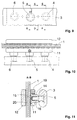
- FIG. 7 shows a first embodiment, at which the horizontal support 3 one essentially rectangular cross section with rounded top and bottom Has guide surfaces.
- the guide rollers 4, 5 and 6 are each concave, so that a lateral guide of the horizontal beam is guaranteed.
- How, for example 7 is on the rollers 4, 5 and 6th each integrally attached to a shaft 15, which by means of a bearing 16 (needle bearing) rotatable in a bearing housing 14 is stored.
- the bearing housing 14 is through a recess the carrier plate 11 inserted and is by the Screwing the support plate 11 held.
- a variant too this embodiment shown in FIG. 7 results 15 and 16.
- There the guide roller is by means of of the bearing 16 mounted directly on a fixed axis 17.
- the axis 17 is by means of a nut 18 with the Bearing housing 14 screwed (see also Fig. 15).
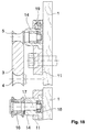
- FIGS. 5 and 6 show in partial section - like FIGS. 5 and 6 - The adjustable arrangement of the second guide roller 5.
- the bearing housing 14 is eccentric Provided flange 20, which in a recess of the support plate 11 is rotatable (see in particular also Fig. 5 and 6).
- the respective screws are fixed by means of the screws 19 Eccentric position of the bearing housing 14. On this Way, it is possible to adjust the guide roller 5 to to ensure a play-free guidance of the carrier 3.
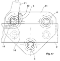
- the horizontal support 3 has in this embodiment a C-shaped cross-section (see in particular 11 to 14), in the interior of which the guide rollers 4, 5 and 6 are arranged.
- the guide rollers 4, 5 and 6 are arranged.
- the inner edges of the carrier 3 crowned, so that a side guide by means of the concave guide rollers 4, 5 and 6 is guaranteed.
- the guide rollers accordingly by means of a bearing housing 14 mounted on the support plate 11.
- the one shown in Fig. 11 The adjustability of the second guide roller 5 is analog Way of the adjustability shown in FIG. 8, an eccentric flange 20 is also provided here. How 17, the eccentric Flange with side contact surfaces for an open-end wrench 21 be provided so that it is easily possible after loosening the screws 19, the bearing housing 14 twist accordingly to adjust the second Ensure guide roller 5.
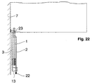
- FIG. 19 to 22 is a simplified plan view Embodiment shown, in which the invention Shower partition, for example as a bathtub partition is installed. From the sequence of FIGS. 19 to 22 results the opening process. Fig. 19 shows the closed Status. An end seal 22 is either against a wall of a building or an additional partition or something similar. By pushing back the second one Cutting disc 2 results in the state shown in FIG. 20. The first cutting disc can now be used together with the second cutting disc can be pivoted about an axis 23, either outside or inside.
- FIG. 23 to 26 show the situation in plan view in a corner shower, in which two according to the invention Shower enclosures are provided.
- 23 shows the completely closed condition.
- Fig. 24 state shown. It is now possible to get the first Swivel cutting discs either outwards or inwards, to ensure free access to the shower tray.
- the pivoting takes place about the axes of rotation 23.
- FIGS. 27 and 28 show an embodiment of an inventive Hinged hinge 10.
- This includes one Bearing block 24, which is in one piece with a mounting plate 25 is provided, which in turn on the wall 7 of the building can be screwed.
- Hinge strap 10 designed as a pendulum.
- bracket 24 is not on a single mounting plate 25, but on a continuous rail 28 attached and itself is also continuously formed (see Fig. 4).
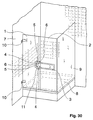
- FIG. 30 shows, analogously to the illustration in FIG. 1, a Corner shower.
- the two carriers 3 In contrast to the configuration according to FIG. 1 are the two carriers 3 at a smaller distance from each other arranged, for example 15 to 20 cm. they are integrally connected to a closed frame.
- the leadership roles 4, 5 and 6 are each, analogous to the embodiment 1, assigned to the upper and lower supports, however, all roles 4, 5 and 6 are on a common one Carrier plate stored.
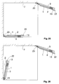
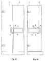
- Figures 31 and 32 show, analogously to Figures 2 and 3 a further embodiment variant of the invention.
- the embodiment of the Figures 31 and 32 for the two together like a frame connected carrier 3 only two upper guide rollers 5 and 6 and a lower guide roller 4.
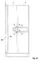
- This construction is shown again in an enlarged view in FIG. 39. It is understood that the horizontal distance of the two guide rollers 5, 6 is correspondingly variable in order to avoid lateral tilting of the second cutting disc.
- FIG. 33 which is analogous to FIG. 4, shows again a support structure according to the embodiment 30.
- Figures 34 to 37 each show variants of the carrier.
- Fig. 34 all corner areas are with large radii provided, while the embodiment of FIG. 35 a shows rectangular shape.
- FIG. 36 there is also a Provided web, which has an additional grip area 29 forms.
- 37 shows a further exemplary embodiment, in which a plate-like basic shape with a plurality of recesses 30 is used.
- Figures 40 and 41 show a schematic representation two further side views of a support structure according to the invention.
- the Carrier plate upper guide rollers 5 and 6 arranged, similar the previously described embodiments.
- two lower rollers 4 are provided for these, which provides additional support for the lower Guide area 3 of the horizontal beam.
- the Height of the frame-shaped horizontal shown in FIG. 40 Carrier can be 80 mm, for example. Even with heavy ones Cutting discs or glass doors ensure that do not tilt and do not tilt. A jamming of the horizontal carrier 3 is thus reliably avoided.
- Fig. 41 shows that one end of the horizontal, frame-shaped support 3 is open can be. It is understood that the U-shaped support also can be used rotated by 180 °.
- Carrier 3 shows a further exemplary embodiment of the invention Carrier 3. This is designed like a frame, the two guide rollers 4 and 5 in the interior of the carrier 3 are arranged.
- the interior can be in its Height slit-shaped and dimensioned so that it is only slightly larger than the diameter of the guide rollers 4, 5.
- the invention is not based on the exemplary embodiments shown limited, rather arise within the scope of the invention diverse modification and modification options. These lie in both the dimensioning and design of the carrier, as well as in the displaceability and Swiveling of both the first cutting disc as well the second cutting disc.
- the shower partition according to the invention is thus a sliding door, to the corner entrance, as a revolving door and can also be used as a folding door.
- the invention can thus universal for all types of showers or bathrooms, with Side entry or corner entry can be used. In summary, the following can be stated:
- the invention relates to a shower enclosure with at least a vertically mounted frameless first cutting disc 1, on which in a plane parallel to the plane of first cutting disc 1 slidably a second cutting disc 2 is held, characterized in that on the second Cutting disc 2 in a plane parallel to this and from the second cutting disc 2 spaced at least one horizontal Carrier 3 is attached, which is longitudinally displaceable by means of at least two guide rollers 4, 5 on the first Cutting disc 1 is mounted.
Landscapes
- Health & Medical Sciences (AREA)
- Public Health (AREA)
- Epidemiology (AREA)
- General Health & Medical Sciences (AREA)
- Bathtubs, Showers, And Their Attachments (AREA)
- Support Devices For Sliding Doors (AREA)
- Percussion Or Vibration Massage (AREA)
- Massaging Devices (AREA)
Abstract
Description
Die Erfindung bezieht sich auf eine Duschabtrennung mit zumindest einer vertikal gelagerten rahmenlosen ersten Trennscheibe, an welcher verschiebbar, in einer Ebene parallel zur Ebene der ersten Trennscheibe eine zweite Trennscheibe gehaltert ist.The invention relates to a shower enclosure with at least a vertically mounted frameless first cutting disc, which is slidable, parallel in one plane to the level of the first cutting disc, a second cutting disc is supported.
Duschabtrennungen mit Schiebetüren sind aus dem Stand der Technik aus unterschiedlichsten Ausgestaltungsformen vorbekannt. Zunächst gibt es eine Vielzahl von Konstruktionen, bei welchen die Trennscheiben in einem Rahmen aufgenommen sind und die einzelnen Rahmen verschiebbar oder teleskopierbar ineinander geführt sind. Derartige Konstruktionen sind für rahmenlose Trennscheiben nicht anwendbar und weisen im übrigen den Nachteil auf, daß die Rahmen sehr dick und massiv sind und gehobenen optischen Anforderungen nicht entsprechen.Shower partitions with sliding doors are state of the art Technology from a wide variety of design forms known. First of all, there are a variety of designs where the cutting discs are accommodated in a frame and the individual frames can be moved or telescoped are brought together. Such constructions are not applicable for frameless cutting discs and show in remaining the disadvantage that the frame is very thick and solid are and do not meet high optical requirements.
Aus der WO 94/24917 ist eine Duschabtrennung vorbekannt, bei welcher die einzelnen Trennscheiben an einem Teleskoparm gelagert sind. Ein derartiger Teleskoparm zeichnet sich zum einen durch ein hohes Bauvolumen und einen komplizierten Aufbau aus, zum anderen ist die verwendete Konstruktion störanfällig und kann leicht verschmutzen. Aus all diesen Gründen hat sich diese Konstruktion nicht bewährt und ist folglich am Markt nicht durchgesetzt.A shower partition is known from WO 94/24917, at which supports the individual cutting discs on a telescopic arm are. Such a telescopic arm is characterized one with a high volume and a complicated one Construction from, on the other hand is the construction used prone to failure and can easily become dirty. From all of these This construction has not proven itself for reasons consequently not established on the market.
Der Erfindung liegt die Aufgabe zugrunde, eine Duschabtrennung der eingangs genannten Art zu schaffen, welche bei einfachem Aufbau, günstiger Herstellbarkeit und leichter Bedienbarkeit eine sichere verschiebbare Lagerung der zweiten Trennscheibe so gewährleistet, daß die Duschabtrennung auch höchsten optischen Anforderungen genügt.The invention has for its object a shower partition to create the type mentioned, which with simple Structure, inexpensive to manufacture and easy to use a secure sliding storage of the second Cutting disc ensures that the shower partition also meets the highest optical requirements.
Erfindungsgemäß wird die Aufgabe durch die Merkmale des Hauptanspruchs gelöst, die Unteransprüche zeigen weitere vorteilhafte Ausgestaltungen der Erfindung.According to the invention, the object is characterized by the features of Main claim solved, the sub-claims show more advantageous embodiments of the invention.
Im Rahmen der Erfindung ist somit vorgesehen, daß an der zweiten Trennscheibe in einer zu dieser parallelen Ebene und von der zweiten Trennscheibe beabstandet zumindest ein horizontaler Träger befestigt ist, welcher längs verschiebbar mittels zumindest zweier Führungsrollen an der ersten Trennscheibe gelagert ist.In the context of the invention it is thus provided that at the second cutting disc in a plane parallel to this and at least one horizontal spaced apart from the second cutting disc Carrier is attached, which is longitudinally displaceable by means of at least two guide rollers on the first cutting disc is stored.
Die erfindungsgemäße Duschabtrennung zeichnet sich durch eine Reihe erheblicher Vorteile aus. Durch die Verwendung zumindest eines horizontalen Trägers, welcher lediglich an zwei Führungsrollen funktionsmäßig gelagert ist, ist ein einfachster Aufbau der Duschabtrennung gewährleistet. Es sind keine komplizierten, verschmutzungsanfälligen oder störungsanfälligen weiteren Komponenten erforderlich, um die Lagerungskraft der zweiten Trennscheibe aufzunehmen und deren Verschiebbarkeit zu gewährleisten. Der horizontale Träger wird somit auf einfachste Weise verschiebbar gelagert, es sind keinerlei Teleskop-Bauelemente erforderlich, der gesamte konstruktive Aufbau ist äußerst einfach und robust. Durch die zwei Führungsrollen, welche bevorzugterweise um zwei parallele, horizontale Achsen drehbar und in günstiger Ausgestaltung entsprechend horizontal beabstandet sind, ergibt sich eine statisch bestimmte, exakte Führung der Träger, welche auch zur Lagerung schwerer Trennscheiben, insbesondere von Glas-Trennscheiben geeignet ist.The shower partition according to the invention is characterized by a A number of significant advantages. By using it at least a horizontal beam, which is only on two guide rollers is functionally supported, is one simplest structure of the shower partition guaranteed. It are not complicated, prone to contamination or prone to malfunction additional components required to the Record the storage power of the second cutting disc and its To ensure displaceability. The horizontal beam is thus slidably supported, no telescope components are required, the whole constructive structure is extremely simple and robust. Due to the two guide rollers, which preferably around two parallel, horizontal axes can be rotated and are cheaper Design are horizontally spaced accordingly, results a statically determined, exact guidance of the carriers, which also for storing heavy cutting discs, in particular of glass cutting discs is suitable.
In einer besonders günstigen Ausgestaltung der Erfindung ist vorgesehen, daß zumindest eine Führungsrolle vertikal einstellbar ist. Diese Ausgestaltung ist eine Alternative zu einer sehr präzisen Fertigung der beiden Führungsrollen sowie deren Lagerung. Durch die Einstellbarkeit ergibt sich die Möglichkeit, geringfügige Montage-Ungenauigkeiten auszugleichen und/oder einen Verzug oder eine Deformation durch ein hohes Gewicht der Trennscheibe zu kompensieren. In a particularly favorable embodiment of the invention provided that at least one guide roller vertically adjustable is. This configuration is an alternative to a very precise production of the two guide rollers as well their storage. The adjustability results in the possibility to compensate for minor assembly inaccuracies and / or a delay or deformation to compensate for a high weight of the cutting disc.
Die vertikal einstellbare Führungsrolle kann beispielsweise mittels eines Exzentermechanismus eingestellt werden. Es ist jedoch auch möglich, die Einstellbarkeit, welche grundsätzlich nur in vertikaler Richtung erfolgen muß, mittels eines einfachen Verstell- oder Schiebemechanismus, beispielsweise mittels Schrauben zu realisieren.The vertically adjustable guide roller can, for example can be adjusted by means of an eccentric mechanism. It is however, the adjustability, which is basically possible only in the vertical direction, using a simple adjustment or sliding mechanism, for example to be realized by means of screws.
Die Führungsrollen sind bevorzugterweise mit Mitteln zur seitlichen Führung des Trägers versehen, so daß auf zusätzliche Maßnahmen verzichtet werden kann. Beispielsweise kann der Träger mittels konkaver Führungsrollen geführt werden. Es ist jedoch auch möglich, an den Führungsrollen seitliche Schultern oder ähnliches vorzusehen, um ein seitliches Verschieben des Trägers zu verhindern.The guide rollers are preferably with means for lateral guide of the carrier provided so that additional Measures can be dispensed with. For example the carrier can be guided using concave guide rollers. However, it is also possible to side on the guide rollers Shoulders or the like should be provided in order to move laterally to prevent the wearer.
Der Träger ist bevorzugterweise mit einem rechteckigen Querschnitt versehen. Bei dieser Ausgestaltungsform ist die erste, der zweiten Trennscheibe zugewandte Führungsrolle unter dem Träger angeordnet, während die zweite Führungsrolle in einem horizontalen Abstand hierzu oberhalb des Trägers gelagert ist. Auf diese Weise wird der Träger statisch bestimmt verschiebbar gehalten. In Verbindung mit den konkaven Rollen kann es günstig sein, wenn die obere und die untere, jeweils eine Lauffläche bildende Seite des Trägers konvex ausgebildet ist.The carrier is preferably of a rectangular cross section Mistake. In this embodiment, the first the second cutting disc facing guide roller under arranged on the carrier, while the second guide roller in a horizontal distance above the beam is. In this way, the carrier is determined statically kept slidable. In conjunction with the concave rollers it may be convenient if the top and bottom, respectively a tread-forming side of the carrier is convex is.
Die beschriebene Lagerung des Trägers mittels zweier Rollen ist bestens dazu geeignet, nach unten wirkende Kräfte, welche durch die zweite Trennscheibe aufgebracht sind, aufzunehmen. Um ein Anheben der zweiten Trennscheibe und damit des Trägers zu verhindern, kann eine dritte Führungsrolle vorgesehen sein, welche beispielsweise oberhalb des Trägers gelagert ist. Es ist jedoch auch möglich, diese dritte Führungsrolle unterhalb des Trägers anzuordnen. Diese dritte Führungsrolle verhindert somit, daß der Träger aus den beiden anderen Führungsrollen ausgehoben wird. Es handelt sich somit um eine reine Sicherheitsmaßnahme. The described mounting of the carrier by means of two rollers is ideally suited to forces acting downwards are applied by the second cutting disc to record. To raise the second cutting disc and thus Preventing the wearer can take a third leadership role be provided, for example above the carrier is stored. However, it is also possible to take this third leadership role to be placed below the carrier. This third Guide roller thus prevents the carrier from the two other leadership roles is lifted. It is about thus a pure security measure.
In einer alternativen Ausgestaltung der Erfindung kann es günstig sein, wenn der Träger einen im wesentlichen C-förmigen Querschnitt aufweist, wobei die erste und die zweite Führungsrolle im Innenraum des Trägers angeordnet sind. Auch diese Führungsrollen sind horizontal zueinander beabstandet und in unterschiedlicher vertikaler Höhe angeordnet, so daß die Führungsrollen zum einen frei drehbar sind und zum anderen jeweils eine nach unten bzw. oben wirkende Kraft aufnehmen können.In an alternative embodiment of the invention, it can be favorable if the carrier is a substantially C-shaped Has cross section, the first and the second Guide roller are arranged in the interior of the carrier. Also these guide rollers are horizontally spaced apart and arranged at different vertical heights, so that the guide rollers are freely rotatable on the one hand and on the other absorb a downward or upward force can.
Auch bei dieser Ausgestaltungsvariante kann es vorteilhaft sein, im Innenraum des Trägers eine dritte Führungsrolle anzuordnen, die zusätzlich einem Anheben der zweiten Trennscheibe entgegenwirkt.It can also be advantageous in this embodiment variant be a third leadership role in the interior of the carrier to arrange the additional lifting of the second cutting disc counteracts.
Um ein Kippen der zweiten Trennscheibe zu verhindern und um diese in exakter Weise zu lagern, kann es vorteilhaft sein, wenn die zweite Trennscheibe mittels zweier paralleler, zueinander beabstandeter Träger zugeordneter Führungsrollen an der ersten Trennscheibe verschiebbar gelagert ist.To prevent the second cutting wheel from tipping over and around storing them in an exact manner, it can be advantageous if the second cutting disc by means of two parallel, to each other spaced carrier associated guide rollers the first cutting disc is slidably mounted.
Alternativ zur Verwendung zweier, zueinander paralleler Träger mit jeweils eigenen Führungsrollen kann es auch vorteilhaft sein, nur einen Träger zu verwenden, welcher eine größere Höhe aufweist. Hierdurch wird der vertikale Abstand der oberen bzw. unteren Führungsrollen vergrößert, so daß sich eine verbesserte Kipp-Stabilität ergibt. Diese Ausgestaltung kann entweder dadurch erreicht werden, daß die beiden zueinander parallelen Träger einen geschlossenen Rahmen bilden. Es ist jedoch auch möglich, nur einen einzigen, plattenartig ausgebildeten Träger zu verwenden. Dieser plattenartige Träger bzw. der geschlossene Rahmen können dabei in vorteilhafter Weise mit einem Griffbereich versehen sein, so daß es nicht erforderlich ist, an der zweiten Trennscheibe zusätzlich einen Betätigungsgriff anzubringen. As an alternative to using two beams that are parallel to each other with their own leadership roles, it can also be beneficial be using only one carrier, which is one has greater height. This will make the vertical distance the upper or lower guide rollers enlarged so that improved tipping stability results. This configuration can either be achieved by the two mutually parallel carrier a closed frame form. However, it is also possible to use only one, to use plate-like supports. This plate-like Carriers or the closed frame can advantageously be provided with a grip area, so that it is not necessary on the second cutting disc additionally attach an operating handle.
Die oben beschriebene Ausgestaltungsvariante, bei welcher entweder die beiden Träger zu einem geschlossenen Rahmen verbunden sind oder ein plattenartiges, einstückiges Element bilden, weist zudem den großen Vorteil auf, daß sämtliche Führungsrollen an einer gemeinsamen Trägerplatte gelagert werden können. Die Zuordnung und Montage der Führungsrollen kann somit in exakter Weise vor der Anbringung der Trägerplatte an der Trennscheibe erfolgen. Somit kann die Montage erheblich vereinfacht werden, es ist insbesondere ein sehr geringes Spiel der Führungsrollen einstellbar, so daß sich ein präziser Lauf des Trägers ergibt.The design variant described above, in which either the two straps into a closed frame are connected or a plate-like, one-piece element form, also has the great advantage that all Guide rollers mounted on a common carrier plate can be. The assignment and assembly of the guide rollers can thus be carried out in an exact manner before attaching the carrier plate on the cutting disc. Thus, the assembly be simplified significantly, it is a very particular one little play of the guide rollers adjustable, so that a precise run of the wearer results.
Erfindungsgemäß versteht es sich, daß an der zweiten Trennscheibe auch in analoger Weise eine dritte Trennscheibe mittels weiterer Träger und Führungsrollen gelagert werden kann.According to the invention it is understood that on the second cutting disc also in a similar way using a third cutting disc additional carriers and guide rollers can be stored can.
Um ein unbeabsichtigtes Herausziehen der zweiten Trennscheibe bzw. des horizontalen Trägers zu verhindern, kann es günstig sein, daß am freien Ende des Trägers ein Stopper oder Anschlag befestigt ist. Dieser kann lösbar ausgebildet sein, um die zweite Trennscheibe zum Reinigen oder zu Montagezwecken entnehmen zu können.To inadvertently pull out the second cutting disc or to prevent the horizontal support, it can be favorable be that at the free end of the carrier a stopper or Stop is attached. This can be designed to be detachable, around the second cutting disc for cleaning or assembly purposes to be able to remove.
Um Verletzungen zu vermeiden, kann es vorteilhaft sein, wenn die Rollen mittels zumindest einer Schutzkappe abgedeckt sind.To avoid injury, it can be beneficial if the roles covered by at least one protective cap are.
Erfindungsgemäß kann der Träger zusätzlich mit Rasterungen versehen sein, um beispielsweise eine ausgefahrene Endstellung oder eine eingefahrene Endstellung der zweiten Trennscheibe festzulegen und dem Benutzer anzuzeigen.According to the invention, the support can also be provided with grids be provided, for example, an extended end position or a retracted end position of the second cutting disc and display it to the user.
Erfindungsgemäß kann die erste Trennscheibe so an einer Wand eines Gebäudes befestigt werden, daß sie entweder einseitig zu öffnen ist oder beidseitig, wie eine Pendeltür, verschwenkt werden kann. Es ist jedoch auch möglich, die erste Trennscheibe feststehend, d.h. nicht bewegbar zu montieren. Die erfindungsgemäße Duschabtrennung eignet sich nicht nur für Duschwannen, sondern auch für Badewannen oder ähnliches. Weiterhin kann die Erfindung auch für andere Trenn- oder Türelemente verwendet werden, die nicht spezifisch Duschen zugeordnet sind, beispielsweise Raumteiler, beispielsweise für Umkleiden in medizinischen Bereichen oder ähnlichem.According to the invention, the first cutting disc can be on a wall of a building that they are either one-sided can be opened or pivoted on both sides, like a swing door can be. However, it is also possible to use the first Cutting disc fixed, i.e. not movable to mount. The shower partition according to the invention is not only suitable for shower trays, but also for bathtubs or the like. Furthermore, the invention can also be used for other separating or Door elements are used that are not specifically showers are assigned, for example room dividers, for example for changing rooms in medical areas or the like.
Bedingt durch die Art der Lagerung des horizontalen Trägers ist es nicht erforderlich, Fette oder Schmiermittel zu verwenden. Vielmehr kann der Träger trocken auf den Führungsrollen geführt werden. Somit ist die Erfindung auch in hygienisch anspruchsvollen Umgebungen, beispielsweise in Krankenhäusern besonders vorteilhaft einsetzbar.Due to the type of storage of the horizontal beam it is not necessary to use greases or lubricants. Rather, the carrier can dry on the guide rollers be performed. Thus, the invention is also in hygienically demanding environments, for example in Hospitals can be used particularly advantageously.
Im folgenden wird die Erfindung anhand von Ausführungsbeispielen in Verbindung mit der Zeichnung beschrieben. Dabei zeigt:
- Fig. 1
- eine schematische perspektivische Darstellung einer Eckdusche unter Verwendung der erfindungsgemäßen Duschabtrennung,
- Fig. 2
- eine Seitenansicht, in vereinfachter Darstellung, der in Fig. 1 gezeigten Anordnung bei geschlossener zweiter Trennscheibe,
- Fig. 3
- eine Seitenansicht, analog Fig. 2, bei geöffneter zweiter Trennscheibe,
- Fig. 4
- eine Ansicht, ähnlich Fig. 2, mit unterschiedlicher Lagerung der erste Trennscheibe,
- Fig. 5
- eine vergrößerte Darstellung des Lagerungsbereichs des erfindungsgemäßen Trägers,
- Fig. 6
- eine Draufsicht auf die in Fig. 5 gezeigte Anordnung,
- Fig. 7
- eine Seitenansicht längs der Schnittlinie A-B von Fig. 5,
- Fig. 8
- eine stirnseitige Ansicht (im Teilschnitt) der in Fig. 5 gezeigten Führungsrolle,
- Fig. 9
- eine Seitenansicht eines weiteren Ausführungsbeispiels der Erfindung,
- Fig. 10
- eine Draufsicht auf die in Fig. 9 gezeigte Anordnung,
- Fig. 11
- eine Schnittansicht längs der Schnittlinie A-B von Fig. 9,
- Fig. 12
- eine Schnittansicht längs der Schnittlinie C-D von Fig. 9,
- Fig. 13
- eine Schnittansicht längs der Schnittlinie E-F von Fig. 9,
- Fig. 14
- eine weitere Schnittansicht eines geänderten Ausführungsbeispiels, ähnlich der Ansicht der Fig. 13,
- Fig. 15
- eine Seitenansicht eines weiteren Ausführungsbeispiels einer erfindungsgemäßen Führungsrolle,
- Fig. 16
- eine Schnittansicht der in Fig. 15 gezeigten Anordnung,
- Fig. 17
- eine vergrößerte Detailansicht des Verstellmechanismus der Führungsrolle, ähnlich der in Fig. 5 gezeigten Ansicht,
- Fig. 18
- eine Seitenansicht, teils im Schnitt, eines Exzenter-Verstellmechanismus für die Führungsrolle,
- Fig. 19
- eine vereinfachte Draufsicht auf ein Ausführungsbeispiel der erfindungsgemäßen Duschabtrennung im vollständig geschlossenen Zustand,
- Fig. 20
- eine Draufsicht, ähnlich Fig. 19, im teilgeöffneten Zustand,
- Fig. 21
- eine Draufsicht, ähnlich Fig. 20, im vollständig geöffneten Zustand bei Verschwenkung der Duschabtrennung zum Duschraum hin,
- Fig. 22
- eine Ansicht analog Fig. 21, bei Verschwenkung der Duschabtrennung vom Duschraum weg,
- Fig. 23
- eine vereinfachte Draufsicht auf ein Ausführungsbeispiel der erfindungsgemäßen Duschabtrennung (im geschlossenen Zustand) bei einer Eckdusche,
- Fig. 24
- eine Draufsicht, analog Fig. 23, im teilgeöffneten Zustand,
- Fig. 25
- eine Draufsicht, ähnlich Fig. 24, bei Verschwenken eines Flügels der Duschabtrennung nach außen,
- Fig. 26
- eine Ansicht ähnlich Fig. 25, bei zusätzlichem Verschwenken eines Flügels der Duschabtrennung nach innen,
- Fig. 27
- eine vereinfachte seitliche Ansicht eines Lagerungsbandes für die erste Trennscheibe,
- Fig. 28
- eine Draufsicht auf die Anordnung gemäß Fig. 27,
- Fig. 29
- eine Draufsicht, teils im Schnitt, eines weiteren Ausführungsbeispiels zur Lagerung der ersten Trennscheibe,
- Fig. 30
- eine schematische perspektivische Darstellung einer Eckdusche, ähnlich Fig. 1, bei welcher die beiden Träger rahmenartig miteinander verbunden sind,
- Fig. 31
- eine stirnseitige Ansicht, ähnlich Fig. 2, in einer gegenüber dem Ausgestaltungsbeispiel der Fig. 30 abgewandelten Lagerungs-Konstruktion,
- Fig. 32
- eine Seitenansicht, analog Fig. 31, bei geöffneter zweiter Trennscheibe,
- Fig. 33
- eine Ansicht, ähnlich Fig. 4, mit unterschiedlicher Lagerung der ersten Trennscheibe,
- Fig. 34
- eine vereinfachte Seitenansicht eines ersten Ausführungsbeispiels des erfindungsgemäßen Doppel-Trägers,
- Fig. 35
- eine Seitenansicht eines weiteren Ausführungsbeispiels eines Doppelträgers,
- Fig. 36
- eine weitere Seitenansicht eines Ausführungsbeispiels eines Doppelträgers,
- Fig. 37
- eine weitere Gestaltungsmöglichkeit des erfindungsgemäßen Trägers,
- Fig. 38
- eine vereinfachte Seiten-Schnittansicht eines weiteren
Ausgestaltungsbeispiels des erfindungsgemäßen
Trägers, analog der Darstellungen in
Figuren 11und 13, - Fig. 39
- eine weitere schematische Seitenansicht eines erfindungsgemäßen Trägers sowie der zugehörigen Lagerung,
- Fig. 40
- eine weitere schematische Seitenansicht, ähnlich Fig. 39, eines Ausführungsbeispiels eines erfindungsgemäßen Trägers sowie der zugehörigen Lagerung,
- Fig. 41
- ein weiteres Ausführungsbeispiel des Trägers, ähnlich Fig. 40, und
- Fig. 42
- eine schematische Darstellung eines weiteren Ausführungsbeispiels eines erfindungsgemäßen Trägers.
- Fig. 1
- 2 shows a schematic perspective illustration of a corner shower using the shower partition according to the invention,
- Fig. 2
- 2 shows a side view, in a simplified representation, of the arrangement shown in FIG. 1 with the second cutting disc closed,
- Fig. 3
- 2 shows a side view, analogous to FIG. 2, with the second cutting disc open,
- Fig. 4
- 2, with different mounting of the first cutting disc,
- Fig. 5
- 2 shows an enlarged representation of the storage area of the carrier according to the invention,
- Fig. 6
- 5 shows a plan view of the arrangement shown in FIG. 5,
- Fig. 7
- 3 shows a side view along the section line AB from FIG. 5,
- Fig. 8
- 3 shows an end view (in partial section) of the guide roller shown in FIG. 5,
- Fig. 9
- a side view of another embodiment of the invention,
- Fig. 10
- 9 shows a plan view of the arrangement shown in FIG. 9,
- Fig. 11
- 6 shows a sectional view along the section line AB from FIG. 9,
- Fig. 12
- 3 shows a sectional view along the section line CD from FIG. 9,
- Fig. 13
- 6 shows a sectional view along the sectional line EF from FIG. 9,
- Fig. 14
- FIG. 4 shows a further sectional view of a modified exemplary embodiment, similar to the view in FIG. 13,
- Fig. 15
- a side view of another embodiment of a guide roller according to the invention,
- Fig. 16
- 15 shows a sectional view of the arrangement shown in FIG. 15,
- Fig. 17
- 3 shows an enlarged detailed view of the adjustment mechanism of the guide roller, similar to the view shown in FIG. 5,
- Fig. 18
- a side view, partly in section, of an eccentric adjustment mechanism for the guide roller,
- Fig. 19
- 2 shows a simplified top view of an exemplary embodiment of the shower partition according to the invention in the fully closed state,
- Fig. 20
- 19 shows a plan view, similar to FIG. 19, in the partially opened state,
- Fig. 21
- 20 shows a top view, similar to FIG. 20, in the fully open state when the shower partition is pivoted toward the shower room,
- Fig. 22
- 21 is a view analogous to FIG. 21, when the shower partition is pivoted away from the shower room,
- Fig. 23
- a simplified plan view of an embodiment of the shower partition according to the invention (in the closed state) in a corner shower,
- Fig. 24
- 23 is a top view, analogous to FIG. 23, in the partially opened state,
- Fig. 25
- 24 is a top view, similar to FIG. 24, when a wing of the shower partition is pivoted outwards,
- Fig. 26
- 25 is a view similar to FIG. 25, with additional pivoting of a wing of the shower partition inwards,
- Fig. 27
- a simplified side view of a storage belt for the first cutting disc,
- Fig. 28
- a plan view of the arrangement of FIG. 27,
- Fig. 29
- 3 shows a plan view, partly in section, of a further exemplary embodiment for mounting the first cutting disc,
- Fig. 30
- 1 shows a schematic perspective illustration of a corner shower, similar to FIG. 1, in which the two supports are connected to one another in a frame-like manner,
- Fig. 31
- 3 shows an end view, similar to FIG. 2, in a bearing construction modified compared to the embodiment example of FIG. 30,
- Fig. 32
- 31 shows a side view, analogous to FIG. 31, with the second cutting disc open,
- Fig. 33
- 4, with different mounting of the first cutting disc,
- Fig. 34
- 2 shows a simplified side view of a first exemplary embodiment of the double beam according to the invention,
- Fig. 35
- a side view of another embodiment of a double girder,
- Fig. 36
- 5 shows a further side view of an exemplary embodiment of a double girder,
- Fig. 37
- another design option for the carrier according to the invention,
- Fig. 38
- a simplified side sectional view of another embodiment of the carrier according to the invention, analogous to the representations in Figures 11 and 13,
- Fig. 39
- another schematic side view of a carrier according to the invention and the associated storage,
- Fig. 40
- 39 shows a further schematic side view, similar to FIG. 39, of an exemplary embodiment of a carrier according to the invention and the associated storage,
- Fig. 41
- another embodiment of the carrier, similar to Fig. 40, and
- Fig. 42
- is a schematic representation of a further embodiment of a carrier according to the invention.
Die Fig. 1 zeigt in schematischer Darstellung eine Eckdusche
mit einer Duschwanne 8, welche von gefliesten Wänden 7 eines
Gebäudes begrenzt wird. Eine Seite der Eckdusche wird durch
eine feststehende Trennwand 9 gebildet, während an der anderen
Seite eine erste Trennscheibe 1 mittels Scharnierbändern
10 gelagert ist. Die erste Trennscheibe kann nach außen oder
nach innen zu öffnen sein, um einen Einstieg in die Dusche
zu ermöglichen.Fig. 1 shows a schematic representation of a corner shower
with a
An der ersten Trennscheibe 1 ist jeweils eine obere und eine
untere Trägerplatte 11 befestigt, bevorzugterweise mittels
einer Verschraubung. Wie beispielsweise in den Fig. 6 und 7
gezeigt, kann die Verschraubung der Trägerplatte 11 mittels
einer Gegenplatte 12 erfolgen.There is an upper and a respective one on the
An der Trägerplatte 11 ist eine erste Führungsrolle 4 sowie
eine zweite Führungsrolle 5 gelagert. Zusätzlich kann eine
dritte Führungsrolle 6 vorgesehen sein. Zwischen den Führungsrollen
4 und 5 ist verschiebbar ein horizontaler Träger
3 geführt, an dessen freiem Ende ein Joch oder Lagerbock 13
angeordnet ist, welches wiederum mit einer zweiten Trennscheibe
2 verbunden ist, bevorzugterweise mittels einer Verschraubung
unter Zuhilfenahme einer Gegendruckplatte.On the
Die erste und die zweite Trennscheibe sind in Form rahmenloser Glasscheiben ausgebildet. The first and second cutting discs are frameless in shape Formed glass panes.
Wie beispielsweise aus den Fig. 1 bis 4 ersichtlich ist,
kann die zweite Trennscheibe 2, welche auf der (bezogen auf
den Duschraum) Innenseite der ersten Trennscheibe angeordnet
ist, parallel zu dieser verschoben werden. Da der horizontale
Träger 3 parallel zu der zweiten Trennscheibe 2 und damit
auch zu der ersten Trennscheibe 1 angeordnet ist, ist es
möglich, diesen außerhalb (bezogen auf den Duschraum) der
ersten Trennscheibe anzubringen, so daß sowohl der Träger
als auch die Führungsrollen nicht mit Spritzwasser beaufschlagt
werden. Hierdurch wird die Reinigung der Duschabtrennung
ganz erheblich erleichtert.As can be seen, for example, from FIGS. 1 to 4,
can the
Die Fig. 6 bis 8 zeigen ein erstes Ausführungsbeispiel, bei
welchem der horizontale Träger 3 einem im wesentlichen
rechteckigen Querschnitt mit abgerundeten oberen und unteren
Führungsflächen aufweist. Die Führungsrollen 4, 5 und 6 sind
jeweils konkav ausgebildet, so daß eine seitliche Führung
des horizontalen Trägers gewährleistet ist. Wie sich beispielsweise
aus Fig. 7 ergibt, ist an den Rollen 4, 5 und 6
jeweils einstückig eine Welle 15 befestigt, welche mittels
eines Lagers 16 (Nadellager) in einem Lagergehäuse 14 drehbar
gelagert ist. Das Lagergehäuse 14 ist durch eine Ausnehmung
der Trägerplatte 11 durchgesteckt und wird durch die
Verschraubung der Trägerplatte 11 gehalten. Eine Variante zu
dieser in Fig. 7 gezeigten Ausgestaltungsform ergibt sich
aus den Fig. 15 und 16. Dort ist die Führungsrolle mittels
des Lagers 16 direkt auf einer feststehenden Achse 17 gelagert.
Die Achse 17 ist mittels einer Mutter 18 mit dem
Lagergehäuse 14 verschraubt (siehe auch Fig. 15).6 to 8 show a first embodiment, at
which the
Die Fig. 8 zeigt im Teilschnitt - wie auch die Fig. 5 und 6
- die verstellbare Anordnung der zweiten Führungsrolle 5.
Das Lagergehäuse 14 ist hierbei mit einem exzentrischen
Flansch 20 versehen, welcher in einer Ausnehmung der Trägerplatte
11 drehbar ist (siehe insbesondere auch Fig. 5 und
6). Mittels der Schrauben 19 erfolgt eine Fixierung der jeweiligen
Exzenterstellung des Lagergehäuses 14. Auf diese
Weise ist es möglich, die Führungsrolle 5 einzustellen, um
eine spielfreie Führung des Trägers 3 zu gewährleisten.8 shows in partial section - like FIGS. 5 and 6
- The adjustable arrangement of the
Die Fig. 9 bis 14 zeigen eine alternative Ausgestaltung des
erfindungsgemäßen Trägers sowie der zugehörigen Führungsrollen.
Der horizontale Träger 3 weist bei diesem Ausführungsbeispiel
einen C-förmigen Querschnitt auf (siehe insbesondere
Fig. 11 bis 14), in dessen Innenraum die Führungsrollen
4, 5 und 6 angeordnet sind. Bei diesem Ausführungsbeispiel
sind die Innenkanten des Trägers 3 ballig, so daß eine Seitenführung
mittels der konkaven Führungsrollen 4, 5 und 6
gewährleistet ist. Auch bei diesem Ausführungsbeispiel sind
die Führungsrollen entsprechend mittels eines Lagergehäuses
14 an der Trägerplatte 11 gelagert. Die in Fig. 11 gezeigte
Einstellbarkeit der zweiten Führungsrolle 5 ist in analoger
Weise zu der in Fig. 8 gezeigten Einstellbarkeit ausgeführt,
auch hier ist ein exzentrischer Flansch 20 vorgesehen. Wie
die Darstellung der Fig. 17 erläutert, kann der exzentrische
Flansch mit seitlichen Angriffsflächen für einen Gabelschlüssel
21 versehen sein, so daß es in leichter Weise möglich
ist, nach Lösen der Schrauben 19 das Lagergehäuse 14
entsprechend zu verdrehen, um eine Einstellung der zweiten
Führungsrolle 5 zu gewährleisten.9 to 14 show an alternative embodiment of the
carrier according to the invention and the associated guide roles.
The
Die Fig. 18 verdeutlicht nochmals die Exzenter-Einstellbarkeit
der Führungsrolle 5.18 again illustrates the adjustability of the eccentric
the
In den Fig. 19 bis 22 ist in der Draufsicht ein vereinfachtes
Ausführungsbeispiel gezeigt, bei welchem die erfindungsgemäße
Duschabtrennung beispielsweise als Badewannen-Abtrennung
eingebaut ist. Aus der Abfolge der Fig. 19 bis 22 ergibt
sich der Öffnungsvorgang. Fig. 19 zeigt den geschlossenen
Zustand. Eine stirnseitige Dichtung 22 liegt entweder
gegen eine Wand eines Gebäudes oder eine zusätzliche Trennwand
oder ähnliches an. Durch Zurückschieben der zweiten
Trennscheibe 2 ergibt sich der in Fig. 20 gezeigte Zustand.
Nachfolgend kann nunmehr die erste Trennscheibe zusammen mit
der zweiten Trennscheibe um eine Achse 23 verschwenkt werden,
entweder nach außen oder nach innen.19 to 22 is a simplified plan view
Embodiment shown, in which the invention
Shower partition, for example as a bathtub partition
is installed. From the sequence of FIGS. 19 to 22 results
the opening process. Fig. 19 shows the closed
Status. An
Die Fig. 23 bis 26 zeigen in der Draufsicht die Situation
bei einer Eckdusche, bei welcher zwei erfindungsgemäße
Duschabtrennungen vorgesehen sind. Die Fig. 23 zeigt den
vollständig geschlossenen Zustand. Durch Verschieben der
zweiten Trennscheiben in Pfeilrichtung ergibt sich der in
Fig. 24 gezeigte Zustand. Es ist nunmehr möglich, die ersten
Trennscheiben entweder nach außen oder nach innen zu verschwenken,
um einen freien Zugang zu der Duschwanne zu gewährleisten.
Die Verschwenkung erfolgt um die Drehachsen 23.23 to 26 show the situation in plan view
in a corner shower, in which two according to the invention
Shower enclosures are provided. 23 shows the
completely closed condition. By moving the
second cutting discs in the direction of the arrow results in
Fig. 24 state shown. It is now possible to get the first
Swivel cutting discs either outwards or inwards,
to ensure free access to the shower tray.
The pivoting takes place about the axes of
Die Fig. 27 und 28 zeigen ein Ausführungsbeispiel eines erfindungsgemäßen
Scharnierbandes 10. Dieses umfaßt einen
Lagerbock 24, welcher einstückig mit einer Befestigungsplatte
25 versehen ist, welche wiederum an der Wand 7 des Gebäudes
verschraubt werden kann. Um eine Drehachse 23 sind zwei
miteinander verschraubte Halteplatten 26 und 27 gelagert,
zwischen welchen eine erste Trennscheibe 1 (nicht gezeigt)
einspannbar ist. Bei diesem Ausführungsbeispiel ist das
Scharnierband 10 als Pendelband ausgestaltet.27 and 28 show an embodiment of an inventive
Hinged
Die Fig. 29 zeigt eine alternative Ausgestaltungsform, bei
welcher der Lagerbock 24 nicht an einer einzelnen Befestigungsplatte
25, sondern an einer durchgehenden Schiene 28
angebracht und selbst ebenfalls durchgehend ausgebildet ist
(siehe Fig. 4).29 shows an alternative embodiment, at
which the
Die Fig. 30 zeigt, analog der Darstellung der Fig. 1, eine
Eckdusche. Im Gegensatz zu der Ausgestaltung gemäß Fig. 1
sind die beiden Träger 3 in einem geringeren Abstand zueinander
angeordnet, beispielsweise 15 bis 20 cm. Sie sind
einstückig zu einem geschlossen Rahmen verbunden. Die Führungsrollen
4, 5 und 6 sind jeweils, analog dem Ausführungsbeispiel
der Fig. 1, dem oberen und dem unteren Träger zugeordnet,
sämtliche Rollen 4, 5 und 6 sind jedoch an einer gemeinsamen
Trägerplatte gelagert.30 shows, analogously to the illustration in FIG. 1, a
Corner shower. In contrast to the configuration according to FIG. 1
are the two
Die Figuren 31 und 32 zeigen, analog den Figuren 2 und 3
eine weitere Ausgestaltungsvariante der Erfindung. Im Gegensatz
zu dem Ausführungsbeispiel der Fig. 30, bei welchem an
dem oberen und an dem unteren Träger jeweils drei Führungsrollen
vorgesehen sind, weist das Ausführungsbeispiel der
Figuren 31 und 32 für die beiden rahmenartig miteinander
verbundenen Träger 3 jeweils nur zwei obere Führungsrollen 5
und 6 sowie eine untere Führungsrolle 4 auf. Diese Konstruktion
ist in vergrößerter Darstellung nochmals in Fig. 39 gezeigt.
Es versteht sich, daß der horizontale Abstand der
beiden Führungsrollen 5, 6 entsprechend variabel ist, um
eine seitliche Kippung der zweiten Trennscheibe zu vermeiden.Figures 31 and 32 show, analogously to Figures 2 and 3
a further embodiment variant of the invention. In contrast
to the embodiment of FIG. 30, in which
three guide rollers each on the upper and on the lower support
are provided, the embodiment of the
Figures 31 and 32 for the two together like a frame
connected
Die Darstellung der Fig. 33, welche analog zur Fig. 4 ist,
zeigt nochmals eine Trägerkonstruktion gemäß dem Ausführungsbeispiel
der Fig. 30.33, which is analogous to FIG. 4,
shows again a support structure according to the
Die Figuren 34 bis 37 zeigen jeweils Varianten der Träger.
In Fig. 34 sind sämtliche Eckbereiche mit großzügigen Radien
versehen, während das Ausführungsbeispiel der Fig. 35 eine
rechteckige Form zeigt. Bei beiden Ausgestaltungsformen bildet
der Übergang zwischen dem oberen und dem unteren Träger
einen Griffbereich 29, der Innenraum zwischen den beiden
Trägern ist in Form einer Ausnehmung 30 ausgebildet.Figures 34 to 37 each show variants of the carrier.
In Fig. 34 all corner areas are with large radii
provided, while the embodiment of FIG. 35 a
shows rectangular shape. Forms in both designs
the transition between the upper and lower beams
a
Bei dem Ausführungsbeispiel der Fig. 36 ist zusätzlich ein
Steg vorgesehen, welcher einen zusätzlichen Griffbereich 29
bildet. Die Fig. 37 zeigt ein weiteres Ausführungsbeispiel,
bei welchem eine plattenartige Grundform mit einer Mehrzahl
von Ausnehmungen 30 verwendet wird.In the embodiment of FIG. 36 there is also a
Provided web, which has an
Durch die oben beschriebene Möglichkeit, zusätzlich einen
Griffbereich 29 auszubilden, vereinfacht sich der gesamte
Aufbau der Duschabtrennung, da es nicht erforderlich ist,
zusätzliche Griffe an den Trennscheiben vorzusehen.Through the possibility described above, an additional one
Forming the
Die Figuren 40 und 41 zeigen in schematischer Darstellung
zwei weitere Seitenansichten einer erfindungsgemaßen Trägerkonstruktion.
Bei diesen Ausführungsbeispielen sind an der
Trägerplatte obere Führungsrollen 5 und 6 angeordnet, ähnlich
den zuvor beschriebenen Ausführungsbeispielen. Im Unterschied
zu diesen sind jedoch zwei untere Rollen 4 vorgesehen,
welche zu einer zusätzlichen Abstützung des unteren
Bereichs 3 des horizontalen Trägers führen. Auf diese Weise
ergibt sich ein hohes Maß an zusätzlicher Stabilität. Die
Höhe des in Fig. 40 gezeigten rahmenförmigen horizontalen
Trägers kann beispielsweise 80 mm betragen. Auch bei schweren
Trennscheiben bzw. Glastüren ist sichergestellt, daß
diese nicht kippen und sich nicht neigen. Ein Verklemmen des
horizontalen Trägers 3 wird somit zuverlässig vermieden.Figures 40 and 41 show a schematic representation
two further side views of a support structure according to the invention.
In these embodiments, the
Carrier plate
Das Ausführungsbeispiel der Fig. 41 zeigt, daß ein Ende des
horizontalen, rahmenförmigen Trägers 3 offen ausgebildet
sein kann. Es versteht sich, daß der U-förmige Träger auch
um 180° gedreht eingesetzt werden kann.The embodiment of Fig. 41 shows that one end of the
horizontal, frame-shaped
Die Fig. 42 zeigt ein weiteres Ausführungsbeispiel des erfindungsgemäßen
Trägers 3. Dieser ist rahmenartig ausgestaltet,
wobei die beiden Führungsrollen 4 und 5 im Innenraum
des Trägers 3 angeordnet sind. Der Innenraum kann in seiner
Höhe schlitzartig ausgebildet und so bemessen sein, daß er
nur geringfügig höher ist, als der Durchmesser der Führungsrollen
4, 5.42 shows a further exemplary embodiment of the
Die Erfindung ist nicht auf die gezeigten Ausführungsbeispiele beschränkt, vielmehr ergeben sich im Rahmen der Erfindung vielfältige Abwandlungs- und Modifikationsmöglichkeiten. Diese liegen sowohl in der Dimensionierung und Ausgestaltung des Trägers, als auch in der Verschiebbarkeit und Verschwenkbarkeit sowohl der ersten Trennscheibe als auch der zweiten Trennscheibe. Die erfindungsgemäße Duschabtrennung ist somit als Schiebetür, zum Eckeinstieg, als Drehtür sowie auch als Falttür verwendbar. Die Erfindung kann somit universal für sämtliche Arten von Duschen oder Bädern, mit Seiteneinstieg oder Eckeinstieg verwendet werden. Zusammenfassend ist folgendes festzustellen:The invention is not based on the exemplary embodiments shown limited, rather arise within the scope of the invention diverse modification and modification options. These lie in both the dimensioning and design of the carrier, as well as in the displaceability and Swiveling of both the first cutting disc as well the second cutting disc. The shower partition according to the invention is thus a sliding door, to the corner entrance, as a revolving door and can also be used as a folding door. The invention can thus universal for all types of showers or bathrooms, with Side entry or corner entry can be used. In summary, the following can be stated:
Die Erfindung bezieht sich auf eine Duschabtrennung mit zumindest
einer vertikal gelagerten rahmenlosen ersten Trennscheibe
1, an welcher in einer Ebene parallel zur Ebene der
ersten Trennscheibe 1 verschiebbar eine zweite Trennscheibe
2 gehaltert ist, dadurch gekennzeichnet, daß an der zweiten
Trennscheibe 2 in einer zu dieser parallelen Ebene und von
der zweiten Trennscheibe 2 beabstandet zumindest ein horizontaler
Träger 3 befestigt ist, welcher längs verschiebbar
mittels zumindest zweier Führungsrollen 4, 5 an der ersten
Trennscheibe 1 gelagert ist.The invention relates to a shower enclosure with at least
a vertically mounted frameless
Claims (27)
Applications Claiming Priority (2)
| Application Number | Priority Date | Filing Date | Title |
|---|---|---|---|
| DE19742139A DE19742139C2 (en) | 1997-09-24 | 1997-09-24 | Shower partition |
| DE19742139 | 1997-09-24 |
Publications (1)
| Publication Number | Publication Date |
|---|---|
| EP0904720A1 true EP0904720A1 (en) | 1999-03-31 |
Family
ID=7843472
Family Applications (1)
| Application Number | Title | Priority Date | Filing Date |
|---|---|---|---|
| EP97121265A Withdrawn EP0904720A1 (en) | 1997-09-24 | 1997-12-03 | Shower partition |
Country Status (4)
| Country | Link |
|---|---|
| US (1) | US5911519A (en) |
| EP (1) | EP0904720A1 (en) |
| CA (1) | CA2225874A1 (en) |
| DE (2) | DE19742139C2 (en) |
Families Citing this family (18)
| Publication number | Priority date | Publication date | Assignee | Title |
|---|---|---|---|---|
| DE10159242A1 (en) * | 2000-10-26 | 2003-06-05 | Andreas Oswald Gmbh | Freestanding partition system with optional sliding door has frameless elements fixed free of floor and ceiling on transverse wall shaped supports through holders with support bolts and L-angles |
| US6966816B2 (en) * | 2001-05-02 | 2005-11-22 | Applied Materials, Inc. | Integrated endpoint detection system with optical and eddy current monitoring |
| US6811466B1 (en) * | 2001-12-28 | 2004-11-02 | Applied Materials, Inc. | System and method for in-line metal profile measurement |
| US6990771B2 (en) * | 2002-09-18 | 2006-01-31 | Architectural Automations, L.L.C. | Inertial control system for opening and closing multiple sliding doors in a common direction |
| DE20304389U1 (en) | 2003-03-18 | 2003-06-05 | Altura Leiden Holding B.V., Vianen | partition wall |
| GB2422539A (en) * | 2005-01-29 | 2006-08-02 | Majestic Shower Company Ltd | Shower enclosure |
| US8061534B2 (en) * | 2006-09-08 | 2011-11-22 | Leviton Manufacturing Co., Inc. | Equipment rack panel system and method |
| JP4189426B2 (en) * | 2007-01-31 | 2008-12-03 | 株式会社東芝 | Sensor device, and portable communication terminal and electronic device using the same |
| CA2853462C (en) * | 2011-10-24 | 2017-06-27 | C.R. Laurence Company, Inc. | Sliding shower door assembly |
| USD740104S1 (en) | 2013-05-31 | 2015-10-06 | Maax Bath Inc. | Shower panel guide |
| USD739210S1 (en) | 2013-05-31 | 2015-09-22 | Maax Bath Inc. | Shower panel guide |
| CN105178631B (en) * | 2013-09-30 | 2019-10-18 | 金少平 | A kind of Simple bathing room with adjustable bottom frame |
| CN105041003B (en) * | 2013-09-30 | 2017-05-24 | 中山市圣莉亚洁具有限公司 | Low-basin shower room |
| EP2868247A1 (en) * | 2013-10-31 | 2015-05-06 | Kohler Co. | Shower door assembly |
| US10455990B2 (en) * | 2016-01-15 | 2019-10-29 | Gus's Kitchen & Bath Limited | Trackless, frameless bi-fold doors for use with a shower or bathtub |
| US10278547B2 (en) * | 2016-05-02 | 2019-05-07 | Maax Bath Inc. | Door assembly for a bathing enclosure |
| CN105840050B (en) * | 2016-05-12 | 2018-01-19 | 福建西河卫浴科技有限公司 | A kind of low obstacle linkage shower house of slide rail type and installation method |
| WO2019173755A1 (en) * | 2018-03-08 | 2019-09-12 | Inlay Door Systems LLC | Sliding door system capable of inline closure and capable of use with corner openings |
Citations (4)
| Publication number | Priority date | Publication date | Assignee | Title |
|---|---|---|---|---|
| DE3105277A1 (en) * | 1981-02-13 | 1982-08-26 | Paul-Jean 7816 Münstertal Munch | Partition for a shower |
| FR2683138A1 (en) * | 1991-11-05 | 1993-05-07 | Algue Sa | Shower or bath screen with telescopic arm to which three glazed panels are fixed, the movement of two of the three being in proportion to each other |
| DE4308413A1 (en) * | 1993-03-17 | 1994-09-22 | Paul Jean Munch | Shower partition wall with sliding door |
| DE29618205U1 (en) * | 1996-10-21 | 1997-02-13 | Dorma Gmbh + Co. Kg, 58256 Ennepetal | Shower partition |
Family Cites Families (6)
| Publication number | Priority date | Publication date | Assignee | Title |
|---|---|---|---|---|
| US4611436A (en) * | 1985-06-17 | 1986-09-16 | Southern Door Company | Sliding door assembly |
| US4785485A (en) * | 1987-01-20 | 1988-11-22 | Keller Industries | Three panel bath enclosure |
| DE3725543C2 (en) * | 1987-08-01 | 1996-10-02 | Hoesch Metall & Kunststoffwerk | Shower partition |
| DE3907986A1 (en) * | 1989-03-11 | 1990-09-13 | Hoesch Metall & Kunststoffwerk | SHOWER PARTITION WITH SLIDING WALL PART |
| US5079872A (en) * | 1990-09-20 | 1992-01-14 | Sterling Plumbing Group, Inc. | Transom assembly for bathing enclosure or the like |
| DE4205784C2 (en) * | 1991-03-28 | 1994-05-11 | Schulte Duschkabinen | Shower partition with linear extension |
-
1997
- 1997-09-24 DE DE19742139A patent/DE19742139C2/en not_active Expired - Fee Related
- 1997-11-24 DE DE29720832U patent/DE29720832U1/en not_active Expired - Lifetime
- 1997-12-03 EP EP97121265A patent/EP0904720A1/en not_active Withdrawn
- 1997-12-23 US US08/997,159 patent/US5911519A/en not_active Expired - Fee Related
- 1997-12-29 CA CA002225874A patent/CA2225874A1/en not_active Abandoned
Patent Citations (4)
| Publication number | Priority date | Publication date | Assignee | Title |
|---|---|---|---|---|
| DE3105277A1 (en) * | 1981-02-13 | 1982-08-26 | Paul-Jean 7816 Münstertal Munch | Partition for a shower |
| FR2683138A1 (en) * | 1991-11-05 | 1993-05-07 | Algue Sa | Shower or bath screen with telescopic arm to which three glazed panels are fixed, the movement of two of the three being in proportion to each other |
| DE4308413A1 (en) * | 1993-03-17 | 1994-09-22 | Paul Jean Munch | Shower partition wall with sliding door |
| DE29618205U1 (en) * | 1996-10-21 | 1997-02-13 | Dorma Gmbh + Co. Kg, 58256 Ennepetal | Shower partition |
Also Published As
| Publication number | Publication date |
|---|---|
| US5911519A (en) | 1999-06-15 |
| DE19742139A1 (en) | 1999-03-25 |
| DE29720832U1 (en) | 1999-01-28 |
| CA2225874A1 (en) | 1999-03-24 |
| DE19742139C2 (en) | 2000-07-06 |
Similar Documents
| Publication | Publication Date | Title |
|---|---|---|
| EP0904720A1 (en) | Shower partition | |
| EP0295513B1 (en) | Partition, specially for corner or round showers | |
| EP1296011B1 (en) | Bi-fold lid | |
| DE3343066A1 (en) | FURNITURE WITH HEIGHT AND / OR INCLINATION TABLE TOP | |
| EP0119514A2 (en) | Space divider | |
| DE69125716T2 (en) | Bathtub umbrella | |
| EP1123670A1 (en) | Corner cupboard door mount | |
| DE3511493C2 (en) | ||
| EP0622043B1 (en) | Shower partition | |
| EP0379965B1 (en) | Waste bin | |
| EP0484932A1 (en) | Shower partition | |
| DE202007003727U1 (en) | Sliding door with recessed telescopic guide rail | |
| DE202005003595U1 (en) | table | |
| DE19911703C1 (en) | Bathroom shower enclosure has bearing rail for sliding frameless shower panel supported by linear guide rail and bearing rollers mounted on fixed frameless shower panel | |
| DE102005003394B4 (en) | Guide system, in particular for shower and bathtub partitions | |
| DE2735248C2 (en) | Drawer slide | |
| EP0779230B1 (en) | Refuse receptacle able to be housed into a piece of furniture | |
| DD294409A5 (en) | HOSPITAL BEDSIDE | |
| EP0477578B1 (en) | Partition wall | |
| DE2418193A1 (en) | Horizontal or vertical swivel door for cupboards - has toothed rods engaging round gear wheels to slide out of sight | |
| EP2492426A2 (en) | Push door system and shower cabinet comprising the push door system | |
| DE2929405C2 (en) | Adjustable suspension device for a piece of furniture that can be fastened to a wall, for example a wall cupboard | |
| EP3533944B1 (en) | Deck construction for a water outlet with adjustable cover suspension | |
| DE3911187A1 (en) | Lifting/tilting window | |
| EP0115604B1 (en) | Sliding element system |
Legal Events
| Date | Code | Title | Description |
|---|---|---|---|
| PUAI | Public reference made under article 153(3) epc to a published international application that has entered the european phase |
Free format text: ORIGINAL CODE: 0009012 |
|
| AK | Designated contracting states |
Kind code of ref document: A1 Designated state(s): AT BE CH DE DK ES FI FR GB GR IE IT LI LU MC NL PT SE |
|
| AX | Request for extension of the european patent |
Free format text: AL;LT;LV;MK;RO;SI |
|
| AKX | Designation fees paid | ||
| STAA | Information on the status of an ep patent application or granted ep patent |
Free format text: STATUS: THE APPLICATION IS DEEMED TO BE WITHDRAWN |
|
| 18D | Application deemed to be withdrawn |
Effective date: 19991001 |
|
| REG | Reference to a national code |
Ref country code: DE Ref legal event code: 8566 |