EP0904117B1 - Intravasale blutpumpe - Google Patents
Intravasale blutpumpe Download PDFInfo
- Publication number
- EP0904117B1 EP0904117B1 EP97916428A EP97916428A EP0904117B1 EP 0904117 B1 EP0904117 B1 EP 0904117B1 EP 97916428 A EP97916428 A EP 97916428A EP 97916428 A EP97916428 A EP 97916428A EP 0904117 B1 EP0904117 B1 EP 0904117B1
- Authority
- EP
- European Patent Office
- Prior art keywords
- impeller
- pump
- housing
- blood pump
- motor
- Prior art date
- Legal status (The legal status is an assumption and is not a legal conclusion. Google has not performed a legal analysis and makes no representation as to the accuracy of the status listed.)
- Expired - Lifetime
Links
Images


Classifications
-
- F—MECHANICAL ENGINEERING; LIGHTING; HEATING; WEAPONS; BLASTING
- F04—POSITIVE - DISPLACEMENT MACHINES FOR LIQUIDS; PUMPS FOR LIQUIDS OR ELASTIC FLUIDS
- F04D—NON-POSITIVE-DISPLACEMENT PUMPS
- F04D29/00—Details, component parts, or accessories
- F04D29/04—Shafts or bearings, or assemblies thereof
- F04D29/046—Bearings
- F04D29/047—Bearings hydrostatic; hydrodynamic
-
- A—HUMAN NECESSITIES
- A61—MEDICAL OR VETERINARY SCIENCE; HYGIENE
- A61M—DEVICES FOR INTRODUCING MEDIA INTO, OR ONTO, THE BODY; DEVICES FOR TRANSDUCING BODY MEDIA OR FOR TAKING MEDIA FROM THE BODY; DEVICES FOR PRODUCING OR ENDING SLEEP OR STUPOR
- A61M60/00—Blood pumps; Devices for mechanical circulatory actuation; Balloon pumps for circulatory assistance
- A61M60/10—Location thereof with respect to the patient's body
- A61M60/122—Implantable pumps or pumping devices, i.e. the blood being pumped inside the patient's body
- A61M60/126—Implantable pumps or pumping devices, i.e. the blood being pumped inside the patient's body implantable via, into, inside, in line, branching on, or around a blood vessel
- A61M60/13—Implantable pumps or pumping devices, i.e. the blood being pumped inside the patient's body implantable via, into, inside, in line, branching on, or around a blood vessel by means of a catheter allowing explantation, e.g. catheter pumps temporarily introduced via the vascular system
-
- A—HUMAN NECESSITIES
- A61—MEDICAL OR VETERINARY SCIENCE; HYGIENE
- A61M—DEVICES FOR INTRODUCING MEDIA INTO, OR ONTO, THE BODY; DEVICES FOR TRANSDUCING BODY MEDIA OR FOR TAKING MEDIA FROM THE BODY; DEVICES FOR PRODUCING OR ENDING SLEEP OR STUPOR
- A61M60/00—Blood pumps; Devices for mechanical circulatory actuation; Balloon pumps for circulatory assistance
- A61M60/20—Type thereof
- A61M60/205—Non-positive displacement blood pumps
- A61M60/216—Non-positive displacement blood pumps including a rotating member acting on the blood, e.g. impeller
-
- A—HUMAN NECESSITIES
- A61—MEDICAL OR VETERINARY SCIENCE; HYGIENE
- A61M—DEVICES FOR INTRODUCING MEDIA INTO, OR ONTO, THE BODY; DEVICES FOR TRANSDUCING BODY MEDIA OR FOR TAKING MEDIA FROM THE BODY; DEVICES FOR PRODUCING OR ENDING SLEEP OR STUPOR
- A61M60/00—Blood pumps; Devices for mechanical circulatory actuation; Balloon pumps for circulatory assistance
- A61M60/30—Medical purposes thereof other than the enhancement of the cardiac output
- A61M60/31—Medical purposes thereof other than the enhancement of the cardiac output for enhancement of in vivo organ perfusion, e.g. retroperfusion
-
- A—HUMAN NECESSITIES
- A61—MEDICAL OR VETERINARY SCIENCE; HYGIENE
- A61M—DEVICES FOR INTRODUCING MEDIA INTO, OR ONTO, THE BODY; DEVICES FOR TRANSDUCING BODY MEDIA OR FOR TAKING MEDIA FROM THE BODY; DEVICES FOR PRODUCING OR ENDING SLEEP OR STUPOR
- A61M60/00—Blood pumps; Devices for mechanical circulatory actuation; Balloon pumps for circulatory assistance
- A61M60/40—Details relating to driving
- A61M60/403—Details relating to driving for non-positive displacement blood pumps
- A61M60/419—Details relating to driving for non-positive displacement blood pumps the force acting on the blood contacting member being permanent magnetic, e.g. from a rotating magnetic coupling between driving and driven magnets
-
- A—HUMAN NECESSITIES
- A61—MEDICAL OR VETERINARY SCIENCE; HYGIENE
- A61M—DEVICES FOR INTRODUCING MEDIA INTO, OR ONTO, THE BODY; DEVICES FOR TRANSDUCING BODY MEDIA OR FOR TAKING MEDIA FROM THE BODY; DEVICES FOR PRODUCING OR ENDING SLEEP OR STUPOR
- A61M60/00—Blood pumps; Devices for mechanical circulatory actuation; Balloon pumps for circulatory assistance
- A61M60/50—Details relating to control
- A61M60/508—Electronic control means, e.g. for feedback regulation
- A61M60/562—Electronic control means, e.g. for feedback regulation for making blood flow pulsatile in blood pumps that do not intrinsically create pulsatile flow
-
- A—HUMAN NECESSITIES
- A61—MEDICAL OR VETERINARY SCIENCE; HYGIENE
- A61M—DEVICES FOR INTRODUCING MEDIA INTO, OR ONTO, THE BODY; DEVICES FOR TRANSDUCING BODY MEDIA OR FOR TAKING MEDIA FROM THE BODY; DEVICES FOR PRODUCING OR ENDING SLEEP OR STUPOR
- A61M60/00—Blood pumps; Devices for mechanical circulatory actuation; Balloon pumps for circulatory assistance
- A61M60/80—Constructional details other than related to driving
- A61M60/802—Constructional details other than related to driving of non-positive displacement blood pumps
- A61M60/81—Pump housings
-
- A—HUMAN NECESSITIES
- A61—MEDICAL OR VETERINARY SCIENCE; HYGIENE
- A61M—DEVICES FOR INTRODUCING MEDIA INTO, OR ONTO, THE BODY; DEVICES FOR TRANSDUCING BODY MEDIA OR FOR TAKING MEDIA FROM THE BODY; DEVICES FOR PRODUCING OR ENDING SLEEP OR STUPOR
- A61M60/00—Blood pumps; Devices for mechanical circulatory actuation; Balloon pumps for circulatory assistance
- A61M60/80—Constructional details other than related to driving
- A61M60/802—Constructional details other than related to driving of non-positive displacement blood pumps
- A61M60/818—Bearings
- A61M60/824—Hydrodynamic or fluid film bearings
-
- A—HUMAN NECESSITIES
- A61—MEDICAL OR VETERINARY SCIENCE; HYGIENE
- A61M—DEVICES FOR INTRODUCING MEDIA INTO, OR ONTO, THE BODY; DEVICES FOR TRANSDUCING BODY MEDIA OR FOR TAKING MEDIA FROM THE BODY; DEVICES FOR PRODUCING OR ENDING SLEEP OR STUPOR
- A61M60/00—Blood pumps; Devices for mechanical circulatory actuation; Balloon pumps for circulatory assistance
- A61M60/80—Constructional details other than related to driving
- A61M60/802—Constructional details other than related to driving of non-positive displacement blood pumps
- A61M60/818—Bearings
- A61M60/825—Contact bearings, e.g. ball-and-cup or pivot bearings
-
- F—MECHANICAL ENGINEERING; LIGHTING; HEATING; WEAPONS; BLASTING
- F04—POSITIVE - DISPLACEMENT MACHINES FOR LIQUIDS; PUMPS FOR LIQUIDS OR ELASTIC FLUIDS
- F04D—NON-POSITIVE-DISPLACEMENT PUMPS
- F04D29/00—Details, component parts, or accessories
- F04D29/04—Shafts or bearings, or assemblies thereof
- F04D29/046—Bearings
- F04D29/0467—Spherical bearings
-
- F—MECHANICAL ENGINEERING; LIGHTING; HEATING; WEAPONS; BLASTING
- F04—POSITIVE - DISPLACEMENT MACHINES FOR LIQUIDS; PUMPS FOR LIQUIDS OR ELASTIC FLUIDS
- F04D—NON-POSITIVE-DISPLACEMENT PUMPS
- F04D29/00—Details, component parts, or accessories
- F04D29/04—Shafts or bearings, or assemblies thereof
- F04D29/046—Bearings
- F04D29/048—Bearings magnetic; electromagnetic
-
- A—HUMAN NECESSITIES
- A61—MEDICAL OR VETERINARY SCIENCE; HYGIENE
- A61M—DEVICES FOR INTRODUCING MEDIA INTO, OR ONTO, THE BODY; DEVICES FOR TRANSDUCING BODY MEDIA OR FOR TAKING MEDIA FROM THE BODY; DEVICES FOR PRODUCING OR ENDING SLEEP OR STUPOR
- A61M60/00—Blood pumps; Devices for mechanical circulatory actuation; Balloon pumps for circulatory assistance
- A61M60/10—Location thereof with respect to the patient's body
- A61M60/122—Implantable pumps or pumping devices, i.e. the blood being pumped inside the patient's body
- A61M60/126—Implantable pumps or pumping devices, i.e. the blood being pumped inside the patient's body implantable via, into, inside, in line, branching on, or around a blood vessel
- A61M60/148—Implantable pumps or pumping devices, i.e. the blood being pumped inside the patient's body implantable via, into, inside, in line, branching on, or around a blood vessel in line with a blood vessel using resection or like techniques, e.g. permanent endovascular heart assist devices
-
- A—HUMAN NECESSITIES
- A61—MEDICAL OR VETERINARY SCIENCE; HYGIENE
- A61M—DEVICES FOR INTRODUCING MEDIA INTO, OR ONTO, THE BODY; DEVICES FOR TRANSDUCING BODY MEDIA OR FOR TAKING MEDIA FROM THE BODY; DEVICES FOR PRODUCING OR ENDING SLEEP OR STUPOR
- A61M60/00—Blood pumps; Devices for mechanical circulatory actuation; Balloon pumps for circulatory assistance
- A61M60/80—Constructional details other than related to driving
- A61M60/802—Constructional details other than related to driving of non-positive displacement blood pumps
- A61M60/804—Impellers
- A61M60/806—Vanes or blades
-
- A—HUMAN NECESSITIES
- A61—MEDICAL OR VETERINARY SCIENCE; HYGIENE
- A61M—DEVICES FOR INTRODUCING MEDIA INTO, OR ONTO, THE BODY; DEVICES FOR TRANSDUCING BODY MEDIA OR FOR TAKING MEDIA FROM THE BODY; DEVICES FOR PRODUCING OR ENDING SLEEP OR STUPOR
- A61M60/00—Blood pumps; Devices for mechanical circulatory actuation; Balloon pumps for circulatory assistance
- A61M60/80—Constructional details other than related to driving
- A61M60/855—Constructional details other than related to driving of implantable pumps or pumping devices
- A61M60/857—Implantable blood tubes
Definitions
- the invention relates to an intravascular blood pump a drive part and a pump part, which by the Vascular system of the human body can be, for example, pumping in the heart to execute.
- An intravascular blood pump is made by puncturing one Blood vessel inserted into the body's vascular system and to the heart or to another place on the blood to be pumped. Those parts that are inserted into the body must be in diameter be so small that the externally accessible fit through large vessels. The largest allowed Diameter is about 7 mm.
- the pump part is a contains tubular housing in which an impeller is rotatably arranged.
- the impeller is over a flexible shaft that passes through a catheter, connected to an extracorporeal drive part.
- the drive part drives the flexible shaft that in turn drives the pump part.
- the drive part because of its extracorporeal operation be tall.
- Lubrication with liquid required Part of this Liquid gets through the slide bearing and seal the pump unit including abrasion into the blood stream.
- the other part is after passing through the catheter collected extracorporeally along the shaft.
- the flexible shaft limits the possible uses the blood pump because these only go to such places in the Bodies can be brought up where none too strong bends of the catheter and the contained therein Shaft are required.
- From W094 / 09835 is a blood pump for the temporary Cardiac support known. That blood pump that used on the open heart, points a rod-shaped housing on which the motor and the Pump contains and with its pump part in the aorta can be used while the engine part is outside the aorta remains.
- a blood pump is also known from EP 0 157 859 B1, in which the motor part and the pump part are structurally are united. This pump is implantable, however is not an intravascular blood pump, which are inserted into the body in a minimally invasive manner can.
- the invention has for its object an intravascular Creating a blood pump, so a blood pump that can be advanced through blood vessels, which with the required large pump capacity is small-sized and simple and safe is sealed.
- Another object of the invention is to provide a to create intravascular blood pump at the risk blood damage due to mechanical shear stress Blood is largely reduced.
- the blood pump according to the invention is characterized by the claim 1 defined.
- the blood pump In the blood pump according to the invention are drive parts and pump part directly connected to each other and the blood pump is designed as a rod-shaped thin part, where motor housing and pump housing essentially have the same outside diameter.
- the diameter a minimally invasive blood pump limited to about 5 to 7 mm because the tube width in the body edge areas a little more than 7 mm is. With such a blood pump, pump performance of approx. 4 l / min. at about 100 mmHg back pressure be generated.
- the impeller in an intravascular blood pump the impeller is arranged on an outside of the motor housing Support bearing axially supported and with the motor shaft via a magnetic coupling through an end wall coupled to the motor housing.
- the front wall is an integral part of the motor housing and seals it from. It is therefore not necessary to have a rotating one Pass the shaft through the motor housing. In order to At this point, seals are omitted, which is the danger cause that they leak or that blood on them.
- the front wall of the engine case consists of non-magnetic material, in particular Plastic or ceramic. There is a possibility to store the impeller on a shaft that is not rotating and through the front wall of the motor housing goes through. The seal between the shaft and the bulkhead is not a problem since both parts are stationary are.
- alignment means are also provided, around the impeller in coaxial alignment with the Keep axis of the motor.
- the impeller is first with respect to the housing with a support bearing axially supported and radially centered.
- a support camp arranged along the axis of the impeller but does not prevent the impeller from oscillating around the support bearing.
- Alignment means provided that are either mechanical, magnetic or hydromechanical type can be and cause the impeller its axial Maintains alignment exactly.
- the central arrangement of the impeller in relation to the pump housing is caused by the support bearing.
- the radial alignment with respect to the longitudinal axis by the alignment means causes separately and at a distance from that Support bearings are provided.
- the one supporting the impeller extends Shaft into the motor housing so that it is a good guidance and constancy of its axial alignment Has. This is important for a beating centric precise guidance of the impeller.
- Such an accurate one Leadership is required as to minimize blood damage and to avoid hydraulic power loss the gap between the blades of the impeller and the pump housing a tenth of a millimeter should exceed. Out of roundness of the impeller rotation would also increase the risk of hemolysis.
- Another advantage of the blood pump is that the impeller can be easily removed and replaced can.
- Form the motor housing and the pump housing a unit to which the impeller is a separate part is exchangeably attached until it is against the support bearing bumps.
- the one from the drive part and the pump housing existing unit can be easily cleaned and disinfected as there are no shaft passages or has moving parts and no gaps are in which contamination can settle.
- the impeller When the impeller rotates, the impeller conveys Blood in the intended direction of flow. It works a force on the impeller that is striving for Pull the impeller off the drive part.
- the magnetic clutch through which the impeller with the motor shaft is coupled, the impeller pulls against the support bearing and prevents the impeller from operating is withdrawn from the support bearing.
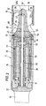
- Fig. 1 is a use of the blood pump 10 for Left heart support shown.
- the blood pump 10 has a motor part 11 and a pump part 12, which are arranged coaxially one behind the other and one rod-shaped design result.
- the pump part is through an intake hose 13 extended at its end and / or openings for blood access in its side wall to the pump. That facing away from the suction hose 13 rear end of the blood pump 10 is with a Connected catheter 14 through the aortic arch 15 and the aorta 16 was introduced.
- the blood pump 10 becomes like this placed that they mainly in the ascending Aorta 16 lies, the straight and short suction hose 13 but protrudes into the heart chamber 17.
- the aortic valve 18 lies on the outside of the Pump housing or the suction hose.
- the blood pump 10 with upstream suction hose 13 is by advancing of the catheter 14, possibly with one contained therein Stylet or using a guide wire, in advanced the position shown.
- the suction hose 13 passes through the aortic valve 18 retrograde, so that blood is drawn through the suction tube 13 and is pumped into the aorta 16.
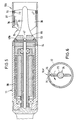
- Fig. 2 shows a preferred embodiment of the Blood pump with the motor part 11 and the firmly connected Pump part 12.
- the motor part 11 has elongated cylindrical housing 20 in which the electric motor 21 is housed. On the back The end of the housing 20 is an end wall 22 closed, to which the flexible catheter 14 seals connects. Pass through catheter 14 i.a. the electrical cables for power supply and Control of the electric motor 21.
- the stator 24 of the motor has numerous in the usual way windings distributed circumferentially, and a magnetic yoke in the longitudinal direction on. It is firmly connected to the motor housing 20.
- the Stator 24 surrounds a rotor 26 that extends in the effective direction magnetized permanent magnet.
- the rotor 26 is arranged rotatably in the motor housing 20.
- the rotor 26 of the motor sits on one with the rotor 26 connected motor shaft 50, which is designed as a hollow shaft and through which a shaft 25 extends.
- the motor shaft 50 is at the rear end with a bearing 51 stored in the motor housing and on the front At the end, it has a bearing 52 on the shaft 25 stored.
- the shaft 25 protrudes through a the front of the motor housing 20th closing end wall 45 in which it is fastened and is sealed stationary.
- the front section of the shaft 25 protrudes into the pump housing 32 inside.
- On this section is the hub 35 of the impeller 34 attached, with this hub 35 itself a support bearing 47 in the form of a ball against that Shaft end supports.
- the support bearing 47 is a combined one Axial / radial bearings.
- the hub 35 contains one Bore 48 with oversize through which the shaft 25 with radial play protrudes so that the hub 35 light Perform pendulum movements around the support bearing 47 can.
- a further extends through the hub 35 Flush bore 48a extending from the front end of the hub to the bore 48 is sufficient to avoid thrombus formation a constant flow through the bore 48 to effect.
- the pump housing 32 is longitudinal Web 49 connected to the motor housing 20.
- vanes 36 or pump blades From the hub 35 of the impeller 34 are vanes 36 or pump blades radially. With a rotation of the Impeller 34 becomes blood through the front suction opening 37 of the pump housing 32 sucked in and in the axial Direction driven in the pump housing 32 to the rear. Through the annular gap between the pump housing 32 and the motor housing 20, the blood flows along the hub 35 widening outward in the direction of flow, to then flow along the motor housing 20.
- Motor housing 20 and pump housing 32 have about the same diameter, however the outer diameter of the pump housing 32 can be somewhat be larger than that of the engine case because that Outside of the pump housing does not have to flow.
- the pump housing 32 consists of a cylindrical tube that is open at the front and rear ends. It is also possible with this and the following examples, operate the pump section with the delivery direction reversed, wherein blood is drawn along the motor housing is and exits axially from the end 37.
- the rotation of the motor shaft 50 is via a magnetic clutch 53 transferred to the impeller 34.
- the Magnetic coupling is connected to the motor shaft 50 first magnetic parts 54 on the inside of the motor housing and second magnetic parts 55 connected to the hub 35.
- the two magnetic parts are due to the non-magnetic End wall 45 magnetically coupled to one another.
- the magnetic Holding force of the clutch 53 is so strong that the force that is striven for when pumping, the impeller 34 to the front (to the right in FIG. 4) drive, overcomes, so that the impeller 34 with the Hub 35 only by magnetic holding force the shaft 25 is held.
- the end wall 45 is like the adjacent walls the magnetic parts 54 and 55 for the interior of the motor housing curved concavely, the support bearing 47 being the center point the bulge forms.
- the clutch is together with the holding force of the Magnetic coupling 53 a radial stabilization of the pendulum on the support bearing 47 suspended hub Liquid damping reached.
- the bulges of the front wall 45 and the adjacent wall of the impeller 34 form an alignment means 56 to the impeller at Pumping operation in coaxial alignment with the shaft 25 to keep.
- the motor housing 20 at its end facing the impeller 34 closed with a flat end wall 45a.
- the rotor 26 is attached to a rotor shaft 60, the rear End with a ball bearing 51 and at its front End is supported with a bearing 61.
- the warehouse 61 has one arranged along the axis of the rotor shaft 60 Ball 62 on that in a conical Pan 63 of the rotor shaft sits and a top bearing forms on which the rotor shaft is axially supported.
- the ball 62 is also seated in a bearing pan a projection 63 is formed, which from the end wall 45a protrudes into the interior of the housing.
- the engine case 20 is completely sealed.
- a magnetic coupling 53 For Transfer of rotation of the rotor shaft 60 to the impeller 34, a magnetic coupling 53 is provided has first magnetic parts 54 which are connected to the rotor shaft 60 connected and arranged inside the motor housing 20 are, and second magnetic parts 55, which on the Impeller 34 are attached.
- the first magnetic parts 54 and the second magnetic parts 55 pass through the End wall 45a through.
- a shaft 64 projects outward from the end wall 45a from which protrudes into the hub 35 of the impeller 34 and with its end against a support bearing 47 Ball hits, which is fixed in the hub 35.
- a Alignment means 56a provided in the form of a plain bearing, which is fixed inside the hub 35 and around the Shaft 64 rotates.
- the support bearing 47 causes an axial Support of the impeller 34 and a highly accurate radial centering. This is countered by the alignment agent 56a in the form of the plain bearing for the fact that an oscillation of the Impeller around the support bearing 47 is prevented, and that the impeller in coaxial alignment with the The axis of the engine remains.
- the ball of the support bearing 47 is preferably made of ceramic or another wear-resistant material. It rotates together with the Impeller.
- the motor is generally in formed in the same way as in Fig. 2.
- the hollow motor shaft 50 extends a shaft 25 which in the rear end wall 22 and in the front End wall 45b is centered and attached.
- the motor shaft 50 is at the rear end with a bearing 51 in Motor housing 20 and at the front end with a bearing 52nd stored on the shaft 25.
- the first magnets 54 attached to a magnetic coupling 53.
- the second magnets 55 of the magnetic coupling are attached to the hub 35 of the impeller 34.
- the support bearing 47 consists of a ball that is centric arranged between the second magnet 55 and is mounted on the end wall 45b of the motor housing 20.
- the support bearing 47 on the motor side End of the impeller 34 arranged so that none of the End wall 45b protruding long support arm required is.
- the alignment means consists of a bearing 56b, which is the upstream end of the hub 35 of the Impeller 34 is supported in the pump housing 32.
- the drive part 11 is the drive part 11 designed in the same way as in Fig. 4.
- the support bearing 47 is in the same way arranged near the end wall 45b of the motor housing 20.
- the alignment means 56c is different.
- This 5 consists of magnets 72, 73, of which the Magnets 72 in the wall of the pump housing 32 and the Magnets 73 arranged in the wings 36 of the impeller 34 are.
- the magnets are arranged in such a way that their poles of the same name face each other and repel each other. That way it will Impeller 34 centered inside the pump housing held.
- the alignment means consists of Bevels 75 on the outer ends of the wings 36 of the impeller 34 are provided, the Distance of the wing 36 from the peripheral wall of the pump housing 32 reduced against the direction of rotation. This means that between the inclined surface 75 and the peripheral wall a pressure build-up occurs in the pump housing 32, which acts on the wing 36 radially inwards. To this A hydrodynamic centering of the Impeller 34.
Description
- Fig. 1
- eine schematische Darstellung der Einführung der Blutpumpe vor den linken Ventrikel, mit Positionierung der Ansaugkanüle im linken Ventrikel,
- Fig. 2
- einen schematischen Längsschnitt eines ersten Ausführungsbeispiels der Blutpumpe,
- Fig. 3
- einen Längsschnitt durch ein zweites Ausführungsbeispiel der Blutpumpe,
- Fig. 4
- einen Längsschnitt durch ein drittes Ausführungsbeispiel der Blutpumpe,
- Fig. 5
- einen Längsschnitt durch ein viertes Ausführungsbeispiel der Blutpumpe und
- Fig. 6
- eine Frontansicht des Flügelrades bei einer abgewandelten weiteren Ausführungsform.
Claims (7)
- Intravasale Blutpumpe mit einem Antriebsteil (11), der in einem Motorgehäuse (20) einen Elektromotor (21) enthält und mit einem Katheter (14) verbunden ist, und einem Pumpenteil (12), der ein in einem rohrförmigen Pumpengehäuse (32) drehbares Flügelrad (34) enthält, wobei das Motorgehäuse (20) und das Pumpengehäuse (32) im wesentlichen gleichen Durchmesser haben und koaxial in axialem Abstand voneinander angeordnet sind,
dadurch gekennzeichnet,
daß das Pumpengehäuse (32) an dem dem Motorgehäuse (20) abgewandten Ende eine stirnseitige Ansaugöffnung (37) aufweist, daß das Flügelrad (34) an einem außerhalb des Motorgehäuses (20) angeordneten Stützlager (47) axial abgestützt ist und mit der Motorwelle (50) über eine Magnetkupplung (53) durch eine Stirnwand (45) des Motorgehäuses (20) hindurch gekoppelt ist, und daß ein Ausrichtmittel (56) vorgesehen ist, welches das Flügelrad (34) in koaxialer Ausrichtung mit der Achse des Pumpengehäuses (32) hält. - Blutpumpe nach Anspruch 1, dadurch gekennzeichnet, daß von der Stirnwand (45,45a) des Motorgehäuses (20) ein Schaft (25,64) absteht, der in eine Axialbohrung (48) des Flügelrades (34) ragt und das Stützlager (47) trägt.
- Blutpumpe nach Anspruch 1 oder 2, dadurch gekennzeichnet, daß das Ausrichtmittel (56) darin besteht, daß die Stirnwand (45) des Motorgehäuses (20) konkav und das benachbarte Ende des Flügelrades (35) konvex ausgebildet ist, so daß an dem Flügelrad entlangströmende Flüssigkeit das um das Stützlager (47) pendelnde Flügelrad (34) zusammen mit der Haltekraft der Magnetkupplung (53) zentriert.
- Blutpumpe nach Anspruch 2, dadurch gekennzeichnet, daß das Ausrichtmittel (56a) aus einem Radiallager besteht, mit dem das Flügelrad (34) auf dem Schaft (64) gelagert ist.
- Blutpumpe nach Anspruch 1, dadurch gekennzeichnet, daß das Ausrichtmittel (56b) aus einem Radiallager besteht, mit dem das die Flügel (36) überragende Ende des Flügelrades gelagert ist und das an dem Pumpengehäuse (32) befestigt ist.
- Blutpumpe nach Anspruch 1, dadurch gekennzeichnet, daß das Ausrichtmittel (56c) darin besteht, daß die Flügel (36) des Flügelrades (34) mit Magneten (73) versehen sind, die zusammen mit Gegenmagneten (72) am Pumpengehäuse (32) eine radiale Zentrierung des Flügelrades (34) bewirken.
- Blutpumpe nach Anspruch 1, dadurch gekennzeichnet, daß das Ausrichtmittel (56d) darin besteht, daß die Enden der Flügel (36) des Flügelrades (34) derart ausgebildet sind, daß beim Rotieren des Flügelrades in dem Pumpengehäuse (32) eine hydrodynamische Zentrierung des Flügelrades (34) erfolgt.
Applications Claiming Priority (3)
| Application Number | Priority Date | Filing Date | Title |
|---|---|---|---|
| DE19613564 | 1996-04-03 | ||
| DE19613564A DE19613564C1 (de) | 1996-04-04 | 1996-04-04 | Intravasale Blutpumpe |
| PCT/EP1997/001661 WO1997037698A1 (de) | 1996-04-04 | 1997-04-02 | Intravasale blutpumpe |
Publications (2)
| Publication Number | Publication Date |
|---|---|
| EP0904117A1 EP0904117A1 (de) | 1999-03-31 |
| EP0904117B1 true EP0904117B1 (de) | 2000-07-12 |
Family
ID=7790513
Family Applications (2)
| Application Number | Title | Priority Date | Filing Date |
|---|---|---|---|
| EP97918098A Expired - Lifetime EP0961621B1 (de) | 1996-04-04 | 1997-04-02 | Intravasale blutpumpe |
| EP97916428A Expired - Lifetime EP0904117B1 (de) | 1996-04-04 | 1997-04-02 | Intravasale blutpumpe |
Family Applications Before (1)
| Application Number | Title | Priority Date | Filing Date |
|---|---|---|---|
| EP97918098A Expired - Lifetime EP0961621B1 (de) | 1996-04-04 | 1997-04-02 | Intravasale blutpumpe |
Country Status (11)
| Country | Link |
|---|---|
| US (1) | US6176848B1 (de) |
| EP (2) | EP0961621B1 (de) |
| JP (2) | JP3570726B2 (de) |
| AT (2) | ATE270562T1 (de) |
| CA (2) | CA2250996A1 (de) |
| DE (3) | DE19613564C1 (de) |
| DK (1) | DK0904117T3 (de) |
| ES (1) | ES2150237T3 (de) |
| GR (1) | GR3034041T3 (de) |
| PT (1) | PT904117E (de) |
| WO (2) | WO1997037696A1 (de) |
Cited By (4)
| Publication number | Priority date | Publication date | Assignee | Title |
|---|---|---|---|---|
| DE102004019718A1 (de) * | 2004-03-18 | 2005-10-06 | Medos Medizintechnik Ag | Pumpe |
| DE102012202411A1 (de) * | 2012-02-16 | 2013-08-22 | Abiomed Europe Gmbh | Intravasale blutpumpe |
| AT515555A4 (de) * | 2014-05-15 | 2015-10-15 | Tech Universität Wien | Magnetkupplung |
| DE112005000636B4 (de) * | 2004-03-18 | 2020-11-05 | Circulite Inc. | Pumpe |
Families Citing this family (158)
| Publication number | Priority date | Publication date | Assignee | Title |
|---|---|---|---|---|
| US5964694A (en) | 1997-04-02 | 1999-10-12 | Guidant Corporation | Method and apparatus for cardiac blood flow assistance |
| US6123725A (en) | 1997-07-11 | 2000-09-26 | A-Med Systems, Inc. | Single port cardiac support apparatus |
| US6532964B2 (en) | 1997-07-11 | 2003-03-18 | A-Med Systems, Inc. | Pulmonary and circulatory blood flow support devices and methods for heart surgery procedures |
| US6889082B2 (en) | 1997-10-09 | 2005-05-03 | Orqis Medical Corporation | Implantable heart assist system and method of applying same |
| DE19821307C1 (de) | 1998-05-13 | 1999-10-21 | Impella Cardiotech Gmbh | Intrakardiale Blutpumpe |
| GB9824436D0 (en) * | 1998-11-06 | 1999-01-06 | Habib Nagy A | Methods of treatment |
| DE29821564U1 (de) * | 1998-12-02 | 2000-07-13 | Impella Cardiotech Ag | Fluidgekühlter Elektromotor mit hoher Leistungsdichte |
| US6123659A (en) * | 1999-01-26 | 2000-09-26 | Nimbus Inc. | Blood pump with profiled outflow region |
| US6186665B1 (en) | 1999-01-26 | 2001-02-13 | Nimbus, Inc. | Motor rotor bearing assembly for a blood pump |
| US7022100B1 (en) * | 1999-09-03 | 2006-04-04 | A-Med Systems, Inc. | Guidable intravascular blood pump and related methods |
| DE29921352U1 (de) * | 1999-12-04 | 2001-04-12 | Impella Cardiotech Ag | Intravasale Blutpumpe |
| DE10040403A1 (de) * | 2000-08-18 | 2002-02-28 | Impella Cardiotech Ag | Intrakardiale Blutpumpe |
| ES2242048T3 (es) | 2001-07-27 | 2005-11-01 | Prof. Dr. Med. Patrick Schauerte | Unidad de neuroestimulacion para la inmovilizacion del corazon durante operaciones de cirugia cardiaca. |
| CA2374989A1 (en) * | 2002-03-08 | 2003-09-08 | Andre Garon | Ventricular assist device comprising a dual inlet hybrid flow blood pump |
| US7241257B1 (en) | 2002-06-28 | 2007-07-10 | Abbott Cardiovascular Systems, Inc. | Devices and methods to perform minimally invasive surgeries |
| US7182769B2 (en) * | 2003-07-25 | 2007-02-27 | Medtronic, Inc. | Sealing clip, delivery systems, and methods |
| US7416525B2 (en) | 2003-09-18 | 2008-08-26 | Myrakelle, Llc | Rotary blood pump |
| US7393181B2 (en) | 2004-09-17 | 2008-07-01 | The Penn State Research Foundation | Expandable impeller pump |
| US20060089521A1 (en) * | 2004-10-21 | 2006-04-27 | Chang Sheldon S L | Rotor driven linear flow blood pump |
| US7479102B2 (en) * | 2005-02-28 | 2009-01-20 | Robert Jarvik | Minimally invasive transvalvular ventricular assist device |
| DE102005017546A1 (de) | 2005-04-16 | 2006-10-19 | Impella Cardiosystems Gmbh | Verfahren zur Steuerung einer Blutpumpe |
| WO2006133209A1 (en) | 2005-06-06 | 2006-12-14 | The Cleveland Clinic Foundation | Blood pump |
| JP5155186B2 (ja) | 2006-01-13 | 2013-02-27 | ハートウェア、インコーポレイテッド | 回転式血液ポンプ |
| US8672611B2 (en) | 2006-01-13 | 2014-03-18 | Heartware, Inc. | Stabilizing drive for contactless rotary blood pump impeller |
| EP1981585B1 (de) * | 2006-01-27 | 2019-03-06 | CircuLite, Inc. | Herzunterstützungssystem |
| JP2009530041A (ja) * | 2006-03-23 | 2009-08-27 | ザ・ペン・ステート・リサーチ・ファンデーション | 拡張可能なインペラポンプを有する心臓補助装置 |
| JP2009532131A (ja) | 2006-03-31 | 2009-09-10 | オーキス メディカル コーポレイション | 回転血液ポンプ |
| US7914436B1 (en) | 2006-06-12 | 2011-03-29 | Abiomed, Inc. | Method and apparatus for pumping blood |
| US8333686B2 (en) | 2006-08-30 | 2012-12-18 | Circulite, Inc. | Cannula insertion devices, systems, and methods including a compressible member |
| JP5537939B2 (ja) * | 2006-08-30 | 2014-07-02 | サーキュライト・インコーポレーテッド | 循環系に補足的な血流を確立するための装置、方法、及びシステム |
| US7905823B2 (en) * | 2006-08-30 | 2011-03-15 | Circulite, Inc. | Devices, methods and systems for establishing supplemental blood flow in the circulatory system |
| JP5457182B2 (ja) * | 2006-09-14 | 2014-04-02 | サーキュライト・インコーポレーテッド | 血管内血液ポンプおよびカテーテル |
| US9028392B2 (en) * | 2006-12-01 | 2015-05-12 | NuCardia, Inc. | Medical device |
| AT504990B1 (de) | 2007-02-27 | 2008-12-15 | Miracor Medizintechnik Handels | Katheter zur unterstützung der leistung eines herzens |
| JP5215580B2 (ja) * | 2007-03-28 | 2013-06-19 | 三菱重工業株式会社 | 人工心臓ポンプ |
| US7828710B2 (en) * | 2007-06-05 | 2010-11-09 | Medical Value Partners, Llc | Apparatus comprising a drive cable for a medical device |
| EP2170449B1 (de) * | 2007-07-19 | 2013-01-16 | CircuLite, Inc. | Kanüle zur herzkammer-implantation und relevante systeme und verfahren |
| US8079948B2 (en) | 2007-08-29 | 2011-12-20 | NuCardia, Inc. | Article comprising an impeller |
| US8489190B2 (en) | 2007-10-08 | 2013-07-16 | Ais Gmbh Aachen Innovative Solutions | Catheter device |
| US8343029B2 (en) * | 2007-10-24 | 2013-01-01 | Circulite, Inc. | Transseptal cannula, tip, delivery system, and method |
| JP5171953B2 (ja) | 2008-06-23 | 2013-03-27 | テルモ株式会社 | 血液ポンプ装置 |
| AU2009302471B2 (en) | 2008-10-06 | 2015-03-19 | Indiana University Research And Technology Corporation | Methods and apparatus for active or passive assistance in the circulatory system |
| EP2372160B1 (de) | 2008-12-08 | 2014-07-30 | Thoratec Corporation | Zentrifugalpumpenvorrichtung |
| JP5378010B2 (ja) | 2009-03-05 | 2013-12-25 | ソラテック コーポレーション | 遠心式ポンプ装置 |
| CN102341600B (zh) | 2009-03-06 | 2014-12-10 | 胸腔科技有限公司 | 离心式泵装置 |
| US8460168B2 (en) * | 2009-03-27 | 2013-06-11 | Circulite, Inc. | Transseptal cannula device, coaxial balloon delivery device, and methods of using the same |
| US20100249491A1 (en) * | 2009-03-27 | 2010-09-30 | Circulite, Inc. | Two-piece transseptal cannula, delivery system, and method of delivery |
| CA2769631A1 (en) | 2009-07-01 | 2011-01-06 | The Penn State Research Foundation | Blood pump with expandable cannula |
| EP2461465B1 (de) | 2009-07-29 | 2018-12-19 | Thoratec Corporation | Rotationsantriebsvorrichtung und zentrifugalpumpenvorrichtung |
| US8690749B1 (en) | 2009-11-02 | 2014-04-08 | Anthony Nunez | Wireless compressible heart pump |
| US20110112353A1 (en) * | 2009-11-09 | 2011-05-12 | Circulite, Inc. | Bifurcated outflow cannulae |
| US8562508B2 (en) * | 2009-12-30 | 2013-10-22 | Thoratec Corporation | Mobility-enhancing blood pump system |
| US9750866B2 (en) | 2010-02-11 | 2017-09-05 | Circulite, Inc. | Cannula lined with tissue in-growth material |
| US8768487B2 (en) * | 2010-02-11 | 2014-07-01 | Circulite, Inc. | Devices, methods and systems for establishing supplemental blood flow in the circulatory system |
| JP5443197B2 (ja) | 2010-02-16 | 2014-03-19 | ソラテック コーポレーション | 遠心式ポンプ装置 |
| JP5572832B2 (ja) | 2010-03-26 | 2014-08-20 | ソーラテック コーポレイション | 遠心式血液ポンプ装置 |
| JP5681403B2 (ja) | 2010-07-12 | 2015-03-11 | ソーラテック コーポレイション | 遠心式ポンプ装置 |
| JP5577506B2 (ja) | 2010-09-14 | 2014-08-27 | ソーラテック コーポレイション | 遠心式ポンプ装置 |
| US8597170B2 (en) | 2011-01-05 | 2013-12-03 | Thoratec Corporation | Catheter pump |
| US8485961B2 (en) | 2011-01-05 | 2013-07-16 | Thoratec Corporation | Impeller housing for percutaneous heart pump |
| WO2012094641A2 (en) * | 2011-01-06 | 2012-07-12 | Thoratec Corporation | Percutaneous heart pump |
| WO2012094535A2 (en) | 2011-01-06 | 2012-07-12 | Thoratec Corporation | Percutaneous heart pump |
| EP2693609B1 (de) | 2011-03-28 | 2017-05-03 | Thoratec Corporation | Dreh- und antriebsvorrichtung und zentrifugalpumpvorrichtung damit |
| KR102109391B1 (ko) | 2011-11-28 | 2020-05-13 | 미-바드, 아이엔씨. | 심실 보조 장치 및 방법 |
| JP6083929B2 (ja) | 2012-01-18 | 2017-02-22 | ソーラテック コーポレイション | 遠心式ポンプ装置 |
| JP2015505515A (ja) | 2012-02-07 | 2015-02-23 | フリダヤ インコーポレーテッドHridaya, Inc. | 血行補助デバイス |
| US11389638B2 (en) * | 2012-02-07 | 2022-07-19 | Hridaya, Inc. | Hemodynamic assist device |
| CA2868853C (en) | 2012-03-26 | 2021-02-09 | Procyrion, Inc. | Systems and methods for fluid flows and/or pressures for circulation and perfusion enhancement |
| GB2504175B (en) * | 2012-05-14 | 2015-01-28 | Thoratec Corp | Distal Bearing Support |
| GB2504176A (en) | 2012-05-14 | 2014-01-22 | Thoratec Corp | Collapsible impeller for catheter pump |
| US8721517B2 (en) | 2012-05-14 | 2014-05-13 | Thoratec Corporation | Impeller for catheter pump |
| US9446179B2 (en) | 2012-05-14 | 2016-09-20 | Thoratec Corporation | Distal bearing support |
| GB2504177B (en) | 2012-05-14 | 2014-12-10 | Thoratec Corp | Sheath system for catheter pump |
| US9327067B2 (en) | 2012-05-14 | 2016-05-03 | Thoratec Corporation | Impeller for catheter pump |
| US9872947B2 (en) | 2012-05-14 | 2018-01-23 | Tc1 Llc | Sheath system for catheter pump |
| US9597205B2 (en) | 2012-06-06 | 2017-03-21 | Magenta Medical Ltd. | Prosthetic renal valve |
| US9421311B2 (en) | 2012-07-03 | 2016-08-23 | Thoratec Corporation | Motor assembly for catheter pump |
| US9358329B2 (en) | 2012-07-03 | 2016-06-07 | Thoratec Corporation | Catheter pump |
| EP4186557A1 (de) | 2012-07-03 | 2023-05-31 | Tc1 Llc | Motoranordnung für katheterpumpe |
| WO2014042925A2 (en) | 2012-09-13 | 2014-03-20 | Circulite, Inc. | Blood flow system with variable speed control |
| US9371826B2 (en) | 2013-01-24 | 2016-06-21 | Thoratec Corporation | Impeller position compensation using field oriented control |
| US9556873B2 (en) | 2013-02-27 | 2017-01-31 | Tc1 Llc | Startup sequence for centrifugal pump with levitated impeller |
| US10583231B2 (en) | 2013-03-13 | 2020-03-10 | Magenta Medical Ltd. | Blood pump |
| US11033728B2 (en) | 2013-03-13 | 2021-06-15 | Tc1 Llc | Fluid handling system |
| EP2968718B1 (de) | 2013-03-13 | 2021-04-21 | Tc1 Llc | Flüssigkeitsbehandlungssystem |
| CA3126978A1 (en) | 2013-03-13 | 2014-09-18 | Magenta Medical Ltd. | Impeller for use with an axial support member |
| US11077294B2 (en) | 2013-03-13 | 2021-08-03 | Tc1 Llc | Sheath assembly for catheter pump |
| WO2014143593A1 (en) | 2013-03-15 | 2014-09-18 | Thoratec Corporation | Catheter pump assembly including a stator |
| US9308302B2 (en) | 2013-03-15 | 2016-04-12 | Thoratec Corporation | Catheter pump assembly including a stator |
| US20140303427A1 (en) | 2013-04-09 | 2014-10-09 | Circulite, Inc. | Blood flow system with operator attachable components |
| US10052420B2 (en) | 2013-04-30 | 2018-08-21 | Tc1 Llc | Heart beat identification and pump speed synchronization |
| US9713663B2 (en) | 2013-04-30 | 2017-07-25 | Tc1 Llc | Cardiac pump with speed adapted for ventricle unloading |
| CA2920101A1 (en) | 2013-08-02 | 2015-02-05 | Circulite, Inc. | Implantable system with secure remote control |
| EP3110468B1 (de) | 2014-02-25 | 2021-11-03 | Kushwaha, Sudhir | Ventrikuläre hilfsvorrichtung und verfahren |
| EP2915496B1 (de) | 2014-03-06 | 2016-11-30 | MPS Micro Precision Systems AG | Implantierbare Vorrichtung |
| WO2015160942A1 (en) | 2014-04-15 | 2015-10-22 | Thoratec Corporation | Catheter pump with off-set motor position |
| WO2015160990A1 (en) | 2014-04-15 | 2015-10-22 | Thoratec Corporation | Catheter pump introducer systems and methods |
| WO2015160943A1 (en) | 2014-04-15 | 2015-10-22 | Thoratec Corporation | Sensors for catheter pumps |
| WO2015160979A1 (en) | 2014-04-15 | 2015-10-22 | Thoratec Corporation | Catheter pump with access ports |
| US10449279B2 (en) | 2014-08-18 | 2019-10-22 | Tc1 Llc | Guide features for percutaneous catheter pump |
| US9623161B2 (en) | 2014-08-26 | 2017-04-18 | Tc1 Llc | Blood pump and method of suction detection |
| US9717832B2 (en) | 2015-01-06 | 2017-08-01 | HeartWave, Inc. | Axial flow rotor with downstream bearing wash flow |
| EP3598986B1 (de) | 2015-01-22 | 2021-02-17 | Tc1 Llc | Motoranordnung mit wärmetauscher für katheterpumpe |
| WO2016118784A1 (en) | 2015-01-22 | 2016-07-28 | Thoratec Corporation | Attachment mechanisms for motor of catheter pump |
| WO2016118777A1 (en) | 2015-01-22 | 2016-07-28 | Thoratec Corporation | Reduced rotational mass motor assembly for catheter pump |
| EP3256183A4 (de) | 2015-02-11 | 2018-09-19 | Tc1 Llc | Herzschlagidentifizierung und pumpengeschwindigkeitssynchronisierung |
| US10371152B2 (en) | 2015-02-12 | 2019-08-06 | Tc1 Llc | Alternating pump gaps |
| US10166318B2 (en) | 2015-02-12 | 2019-01-01 | Tc1 Llc | System and method for controlling the position of a levitated rotor |
| US10245361B2 (en) | 2015-02-13 | 2019-04-02 | Tc1 Llc | Impeller suspension mechanism for heart pump |
| JP6445363B2 (ja) * | 2015-03-20 | 2018-12-26 | テルモ株式会社 | 医療用装置 |
| US9907890B2 (en) | 2015-04-16 | 2018-03-06 | Tc1 Llc | Catheter pump with positioning brace |
| US11291824B2 (en) | 2015-05-18 | 2022-04-05 | Magenta Medical Ltd. | Blood pump |
| EP3331596A4 (de) | 2015-09-14 | 2019-04-03 | Thoratec Corporation | Flüssigkeitsbehandlungssystem |
| US10117983B2 (en) | 2015-11-16 | 2018-11-06 | Tc1 Llc | Pressure/flow characteristic modification of a centrifugal pump in a ventricular assist device |
| EP3222301B1 (de) * | 2016-03-23 | 2018-05-09 | Abiomed Europe GmbH | Blutpumpe |
| US10166319B2 (en) | 2016-04-11 | 2019-01-01 | CorWave SA | Implantable pump system having a coaxial ventricular cannula |
| US9968720B2 (en) | 2016-04-11 | 2018-05-15 | CorWave SA | Implantable pump system having an undulating membrane |
| EP3808401A1 (de) | 2016-07-21 | 2021-04-21 | Tc1 Llc | Gasgefüllte kammer für eine katheterpumpenmotoranordnung |
| US11160970B2 (en) | 2016-07-21 | 2021-11-02 | Tc1 Llc | Fluid seals for catheter pump motor assembly |
| EP3515524B1 (de) | 2016-09-23 | 2020-12-30 | Heartware, Inc. | Blutpumpe mit sensoren auf der gehäuseoberfläche |
| JP7383476B2 (ja) | 2016-10-25 | 2023-11-20 | マジェンタ・メディカル・リミテッド | 心室補助デバイス |
| EP3319098A1 (de) | 2016-11-02 | 2018-05-09 | Abiomed Europe GmbH | Intravaskuläre blutpumpe mit korrosionsbeständigem dauermagneten |
| WO2018089970A1 (en) | 2016-11-14 | 2018-05-17 | Tc1 Llc | Sheath assembly for catheter pump |
| CN110049792B (zh) | 2016-11-23 | 2022-01-18 | 马真塔医药有限公司 | 血泵 |
| EP3600479A1 (de) | 2017-03-31 | 2020-02-05 | Corwave SA | Implantierbares pumpensystem mit einer rechteckigen membran |
| EP3634528B1 (de) | 2017-06-07 | 2023-06-07 | Shifamed Holdings, LLC | Intravaskuläre fluidbewegungsvorrichtungen, systeme und verwendungsverfahren |
| CN107456617B (zh) * | 2017-08-08 | 2023-11-14 | 长治市久安人工心脏科技开发有限公司 | 一种无后导叶植入式轴流血泵 |
| WO2019035804A1 (en) * | 2017-08-14 | 2019-02-21 | Heartware, Inc. | SYSTEM FOR CONNECTING A PUMP TO AN ENGINE |
| US10780206B2 (en) | 2017-08-14 | 2020-09-22 | Heartware, Inc. | Pump to motor connection system |
| FR3073578B1 (fr) | 2017-11-10 | 2019-12-13 | Corwave | Circulateur de fluide a membrane ondulante |
| CN111556763B (zh) | 2017-11-13 | 2023-09-01 | 施菲姆德控股有限责任公司 | 血管内流体运动装置、系统 |
| US10188779B1 (en) | 2017-11-29 | 2019-01-29 | CorWave SA | Implantable pump system having an undulating membrane with improved hydraulic performance |
| CN111801069A (zh) * | 2017-11-30 | 2020-10-20 | 淼保尔斯医疗科技法国股份公司 | 含模块化结构的医疗级致动器和包括该致动器的医疗设备 |
| US10905808B2 (en) | 2018-01-10 | 2021-02-02 | Magenta Medical Ltd. | Drive cable for use with a blood pump |
| DE102018201030A1 (de) | 2018-01-24 | 2019-07-25 | Kardion Gmbh | Magnetkuppelelement mit magnetischer Lagerungsfunktion |
| EP4085965A1 (de) | 2018-02-01 | 2022-11-09 | Shifamed Holdings, LLC | Intravaskuläre blutpumpen und verfahren zur verwendung und herstellung |
| US11813443B2 (en) | 2018-03-09 | 2023-11-14 | Boston Scientific Scimed, Inc. | Magnetic coupler for hemostatic rotor sealing |
| WO2019178173A1 (en) | 2018-03-14 | 2019-09-19 | The Cleveland Clinic Foundation | Blood pump with magnetically loaded partial arc journal bearings |
| DK3542837T3 (da) | 2018-03-23 | 2020-09-21 | Abiomed Europe Gmbh | Intravaskulær blodpumpe |
| DE102018211327A1 (de) * | 2018-07-10 | 2020-01-16 | Kardion Gmbh | Laufrad für ein implantierbares, vaskuläres Unterstützungssystem |
| WO2020152611A2 (en) | 2019-01-24 | 2020-07-30 | Magenta Medical Ltd | Ventricular assist device |
| CN113795295A (zh) | 2019-03-15 | 2021-12-14 | 科瓦韦公司 | 用于控制可植入血泵的系统及方法 |
| US11964145B2 (en) | 2019-07-12 | 2024-04-23 | Shifamed Holdings, Llc | Intravascular blood pumps and methods of manufacture and use |
| US11654275B2 (en) | 2019-07-22 | 2023-05-23 | Shifamed Holdings, Llc | Intravascular blood pumps with struts and methods of use and manufacture |
| US11724089B2 (en) | 2019-09-25 | 2023-08-15 | Shifamed Holdings, Llc | Intravascular blood pump systems and methods of use and control thereof |
| EP4093480A1 (de) * | 2020-01-21 | 2022-11-30 | Boston Scientific Scimed Inc. | Elektromagnetisch angetriebene blutpumpe |
| DE102020102474A1 (de) | 2020-01-31 | 2021-08-05 | Kardion Gmbh | Pumpe zum Fördern eines Fluids und Verfahren zum Herstellen einer Pumpe |
| WO2021158967A1 (en) * | 2020-02-05 | 2021-08-12 | Shifamed Holdings, Llc | Intravascular blood pumps, motors, and fluid control |
| EP4114504A1 (de) | 2020-03-06 | 2023-01-11 | CorWave SA | Implantierbare blutpumpe, die ein linearlager umfasst |
| JP2023524020A (ja) | 2020-04-29 | 2023-06-08 | アビオメド インコーポレイテッド | 血液ポンプをパージする方法 |
| CN115474950A (zh) * | 2021-06-15 | 2022-12-16 | 浙江迪远医疗器械有限公司 | 能够防凝血的血液泵 |
| WO2023014742A1 (en) * | 2021-08-04 | 2023-02-09 | Kardion Gmbh | Seal for a mechanical circulatory support device |
| US20230134031A1 (en) | 2021-10-29 | 2023-05-04 | Abiomed, Inc. | CONTROLLED PURGE RECOVERY USING TISSUE PLASMINOGEN ACTIVATOR (tPA) |
| WO2023091454A1 (en) * | 2021-11-16 | 2023-05-25 | Boston Scientific Scimed Inc. | Percutaneous circulatory support system facilitating reduced hemolysis |
| WO2023091452A1 (en) * | 2021-11-16 | 2023-05-25 | Boston Scientific Scimed Inc. | Percutaneous circulatory support system facilitating reduced hemolysis |
| CN114796845A (zh) * | 2021-12-03 | 2022-07-29 | 深圳核心医疗科技有限公司 | 血泵及其驱动装置 |
| WO2023158870A2 (en) * | 2022-02-21 | 2023-08-24 | Abiomed, Inc. | Method of purging a blood pump |
| CN115025387B (zh) * | 2022-07-08 | 2023-05-30 | 深圳核心医疗科技股份有限公司 | 驱动装置和血泵 |
Family Cites Families (29)
| Publication number | Priority date | Publication date | Assignee | Title |
|---|---|---|---|---|
| US3568659A (en) | 1968-09-24 | 1971-03-09 | James N Karnegis | Disposable percutaneous intracardiac pump and method of pumping blood |
| US4382199A (en) | 1980-11-06 | 1983-05-03 | Nu-Tech Industries, Inc. | Hydrodynamic bearing system for a brushless DC motor |
| US4688998A (en) | 1981-03-18 | 1987-08-25 | Olsen Don B | Magnetically suspended and rotated impellor pump apparatus and method |
| US5078741A (en) | 1986-10-12 | 1992-01-07 | Life Extenders Corporation | Magnetically suspended and rotated rotor |
| US4704121A (en) | 1983-09-28 | 1987-11-03 | Nimbus, Inc. | Anti-thrombogenic blood pump |
| US4625712A (en) * | 1983-09-28 | 1986-12-02 | Nimbus, Inc. | High-capacity intravascular blood pump utilizing percutaneous access |
| US4779614A (en) | 1987-04-09 | 1988-10-25 | Nimbus Medical, Inc. | Magnetically suspended rotor axial flow blood pump |
| US4846152A (en) | 1987-11-24 | 1989-07-11 | Nimbus Medical, Inc. | Single-stage axial flow blood pump |
| US4817586A (en) * | 1987-11-24 | 1989-04-04 | Nimbus Medical, Inc. | Percutaneous bloom pump with mixed-flow output |
| US5061256A (en) | 1987-12-07 | 1991-10-29 | Johnson & Johnson | Inflow cannula for intravascular blood pumps |
| US4895557A (en) | 1987-12-07 | 1990-01-23 | Nimbus Medical, Inc. | Drive mechanism for powering intravascular blood pumps |
| US5092879A (en) | 1988-02-17 | 1992-03-03 | Jarvik Robert K | Intraventricular artificial hearts and methods of their surgical implantation and use |
| US4906229A (en) | 1988-05-03 | 1990-03-06 | Nimbus Medical, Inc. | High-frequency transvalvular axisymmetric blood pump |
| US4908012A (en) | 1988-08-08 | 1990-03-13 | Nimbus Medical, Inc. | Chronic ventricular assist system |
| US4919647A (en) | 1988-10-13 | 1990-04-24 | Kensey Nash Corporation | Aortically located blood pumping catheter and method of use |
| US5112292A (en) | 1989-01-09 | 1992-05-12 | American Biomed, Inc. | Helifoil pump |
| US4944722A (en) | 1989-02-23 | 1990-07-31 | Nimbus Medical, Inc. | Percutaneous axial flow blood pump |
| US5017103A (en) * | 1989-03-06 | 1991-05-21 | St. Jude Medical, Inc. | Centrifugal blood pump and magnetic coupling |
| US5211546A (en) * | 1990-05-29 | 1993-05-18 | Nu-Tech Industries, Inc. | Axial flow blood pump with hydrodynamically suspended rotor |
| KR100303616B1 (ko) | 1992-04-14 | 2001-11-30 | 마에다 시게루 | 캔드모터용카트리지타입베어링장치,캔드모터,및전주류형인라인펌프 |
| US5376114A (en) * | 1992-10-30 | 1994-12-27 | Jarvik; Robert | Cannula pumps for temporary cardiac support and methods of their application and use |
| US5393207A (en) | 1993-01-21 | 1995-02-28 | Nimbus, Inc. | Blood pump with disposable rotor assembly |
| JP2569419B2 (ja) * | 1993-02-18 | 1997-01-08 | 工業技術院長 | 人工心臓用ポンプ |
| JPH06346917A (ja) * | 1993-06-03 | 1994-12-20 | Shicoh Eng Co Ltd | 一方向性動圧軸受を用いた耐圧防水シ−ル機構 |
| US5507629A (en) | 1994-06-17 | 1996-04-16 | Jarvik; Robert | Artificial hearts with permanent magnet bearings |
| US5503615A (en) * | 1994-08-26 | 1996-04-02 | Goldstein; Bernard | Implantable cardiac ventricular assist device and controller thereof |
| US5695471A (en) * | 1996-02-20 | 1997-12-09 | Kriton Medical, Inc. | Sealless rotary blood pump with passive magnetic radial bearings and blood immersed axial bearings |
| US5911685A (en) | 1996-04-03 | 1999-06-15 | Guidant Corporation | Method and apparatus for cardiac blood flow assistance |
| US5964694A (en) | 1997-04-02 | 1999-10-12 | Guidant Corporation | Method and apparatus for cardiac blood flow assistance |
-
1996
- 1996-04-04 DE DE19613564A patent/DE19613564C1/de not_active Expired - Fee Related
-
1997
- 1997-04-02 DE DE59702014T patent/DE59702014D1/de not_active Expired - Lifetime
- 1997-04-02 DK DK97916428T patent/DK0904117T3/da active
- 1997-04-02 WO PCT/EP1997/001652 patent/WO1997037696A1/de active IP Right Grant
- 1997-04-02 ES ES97916428T patent/ES2150237T3/es not_active Expired - Lifetime
- 1997-04-02 WO PCT/EP1997/001661 patent/WO1997037698A1/de active IP Right Grant
- 1997-04-02 AT AT97918098T patent/ATE270562T1/de not_active IP Right Cessation
- 1997-04-02 EP EP97918098A patent/EP0961621B1/de not_active Expired - Lifetime
- 1997-04-02 US US09/155,818 patent/US6176848B1/en not_active Expired - Lifetime
- 1997-04-02 AT AT97916428T patent/ATE194500T1/de not_active IP Right Cessation
- 1997-04-02 CA CA002250996A patent/CA2250996A1/en not_active Abandoned
- 1997-04-02 PT PT97916428T patent/PT904117E/pt unknown
- 1997-04-02 EP EP97916428A patent/EP0904117B1/de not_active Expired - Lifetime
- 1997-04-02 JP JP53581897A patent/JP3570726B2/ja not_active Expired - Lifetime
- 1997-04-02 CA CA002250852A patent/CA2250852A1/en not_active Abandoned
- 1997-04-02 DE DE59711768T patent/DE59711768D1/de not_active Expired - Lifetime
- 1997-04-02 JP JP53581197A patent/JP3694031B2/ja not_active Expired - Lifetime
-
2000
- 2000-07-27 GR GR20000401731T patent/GR3034041T3/el not_active IP Right Cessation
Cited By (9)
| Publication number | Priority date | Publication date | Assignee | Title |
|---|---|---|---|---|
| DE102004019718A1 (de) * | 2004-03-18 | 2005-10-06 | Medos Medizintechnik Ag | Pumpe |
| DE112005001144B4 (de) * | 2004-03-18 | 2017-02-02 | Medos Medizintechnik Ag | Pumpe |
| DE112005000636B4 (de) * | 2004-03-18 | 2020-11-05 | Circulite Inc. | Pumpe |
| DE102012202411A1 (de) * | 2012-02-16 | 2013-08-22 | Abiomed Europe Gmbh | Intravasale blutpumpe |
| US9550017B2 (en) | 2012-02-16 | 2017-01-24 | Abiomed Europe Gmbh | Intravascular blood pump |
| DE102012202411B4 (de) * | 2012-02-16 | 2018-07-05 | Abiomed Europe Gmbh | Intravasale blutpumpe |
| AT515555A4 (de) * | 2014-05-15 | 2015-10-15 | Tech Universität Wien | Magnetkupplung |
| AT515555B1 (de) * | 2014-05-15 | 2015-10-15 | Tech Universität Wien | Magnetkupplung |
| WO2015172173A2 (de) | 2014-05-15 | 2015-11-19 | Technische Universität Wien | Magnetkupplung |
Also Published As
| Publication number | Publication date |
|---|---|
| ATE270562T1 (de) | 2004-07-15 |
| ES2150237T3 (es) | 2000-11-16 |
| ATE194500T1 (de) | 2000-07-15 |
| JP2001515374A (ja) | 2001-09-18 |
| JP2001517102A (ja) | 2001-10-02 |
| EP0961621B1 (de) | 2004-07-07 |
| WO1997037696A1 (de) | 1997-10-16 |
| EP0904117A1 (de) | 1999-03-31 |
| DK0904117T3 (da) | 2000-11-20 |
| EP0961621A1 (de) | 1999-12-08 |
| JP3694031B2 (ja) | 2005-09-14 |
| JP3570726B2 (ja) | 2004-09-29 |
| DE59711768D1 (de) | 2004-08-12 |
| US6176848B1 (en) | 2001-01-23 |
| CA2250996A1 (en) | 1997-10-16 |
| PT904117E (pt) | 2000-10-31 |
| WO1997037698A1 (de) | 1997-10-16 |
| DE59702014D1 (de) | 2000-08-17 |
| DE19613564C1 (de) | 1998-01-08 |
| CA2250852A1 (en) | 1997-10-16 |
| GR3034041T3 (en) | 2000-11-30 |
Similar Documents
| Publication | Publication Date | Title |
|---|---|---|
| EP0904117B1 (de) | Intravasale blutpumpe | |
| DE69629255T2 (de) | Herzunterstützungsvorrichtung | |
| EP3628344B1 (de) | Blutpumpe | |
| EP2366412B1 (de) | Katheter-Vorrichtung | |
| EP1360416B1 (de) | Vorrichtung zur axialen förderung von flüssigkeiten | |
| EP2298374B1 (de) | Katheter-Vorrichtung | |
| EP2051751B1 (de) | Blutpumpe | |
| DE102010011998A1 (de) | Fluidpumpeinrichtung | |
| EP1416163B1 (de) | Kreiselpumpe mit Auswaschung der Fugenspalte | |
| WO1998028543A2 (de) | Vorrichtung zur schonenden förderung von ein- und mehrphasigen fluiden |
Legal Events
| Date | Code | Title | Description |
|---|---|---|---|
| PUAI | Public reference made under article 153(3) epc to a published international application that has entered the european phase |
Free format text: ORIGINAL CODE: 0009012 |
|
| 17P | Request for examination filed |
Effective date: 19980918 |
|
| AK | Designated contracting states |
Kind code of ref document: A1 Designated state(s): AT BE CH DE DK ES FI FR GB GR IE IT LI NL PT SE |
|
| GRAG | Despatch of communication of intention to grant |
Free format text: ORIGINAL CODE: EPIDOS AGRA |
|
| 17Q | First examination report despatched |
Effective date: 19990506 |
|
| GRAG | Despatch of communication of intention to grant |
Free format text: ORIGINAL CODE: EPIDOS AGRA |
|
| GRAH | Despatch of communication of intention to grant a patent |
Free format text: ORIGINAL CODE: EPIDOS IGRA |
|
| RAP3 | Party data changed (applicant data changed or rights of an application transferred) |
Owner name: IMPELLA CARDIOTECHNIK AKTIENGESELLSCHAFT |
|
| GRAH | Despatch of communication of intention to grant a patent |
Free format text: ORIGINAL CODE: EPIDOS IGRA |
|
| GRAA | (expected) grant |
Free format text: ORIGINAL CODE: 0009210 |
|
| AK | Designated contracting states |
Kind code of ref document: B1 Designated state(s): AT BE CH DE DK ES FI FR GB GR IE IT LI NL PT SE |
|
| REF | Corresponds to: |
Ref document number: 194500 Country of ref document: AT Date of ref document: 20000715 Kind code of ref document: T |
|
| RIN1 | Information on inventor provided before grant (corrected) |
Inventor name: SIESS, THORSTEN Inventor name: REUL, HELMUT Inventor name: RAU, GUNTER |
|
| REG | Reference to a national code |
Ref country code: CH Ref legal event code: NV Representative=s name: TROESCH SCHEIDEGGER WERNER AG Ref country code: CH Ref legal event code: EP |
|
| REG | Reference to a national code |
Ref country code: IE Ref legal event code: FG4D Free format text: GERMAN |
|
| REF | Corresponds to: |
Ref document number: 59702014 Country of ref document: DE Date of ref document: 20000817 |
|
| ITF | It: translation for a ep patent filed |
Owner name: ING. A. GIAMBROCONO & C. S.R.L. |
|
| ET | Fr: translation filed | ||
| GBT | Gb: translation of ep patent filed (gb section 77(6)(a)/1977) |
Effective date: 20000925 |
|
| REG | Reference to a national code |
Ref country code: PT Ref legal event code: SC4A Free format text: AVAILABILITY OF NATIONAL TRANSLATION Effective date: 20000713 |
|
| REG | Reference to a national code |
Ref country code: ES Ref legal event code: FG2A Ref document number: 2150237 Country of ref document: ES Kind code of ref document: T3 |
|
| REG | Reference to a national code |
Ref country code: DK Ref legal event code: T3 |
|
| PLBE | No opposition filed within time limit |
Free format text: ORIGINAL CODE: 0009261 |
|
| STAA | Information on the status of an ep patent application or granted ep patent |
Free format text: STATUS: NO OPPOSITION FILED WITHIN TIME LIMIT |
|
| 26N | No opposition filed | ||
| REG | Reference to a national code |
Ref country code: GB Ref legal event code: IF02 |
|
| PGFP | Annual fee paid to national office [announced via postgrant information from national office to epo] |
Ref country code: PT Payment date: 20020321 Year of fee payment: 6 |
|
| PGFP | Annual fee paid to national office [announced via postgrant information from national office to epo] |
Ref country code: BE Payment date: 20020419 Year of fee payment: 6 Ref country code: AT Payment date: 20020419 Year of fee payment: 6 |
|
| PGFP | Annual fee paid to national office [announced via postgrant information from national office to epo] |
Ref country code: FI Payment date: 20020422 Year of fee payment: 6 Ref country code: DK Payment date: 20020422 Year of fee payment: 6 Ref country code: CH Payment date: 20020422 Year of fee payment: 6 |
|
| PGFP | Annual fee paid to national office [announced via postgrant information from national office to epo] |
Ref country code: GR Payment date: 20020426 Year of fee payment: 6 |
|
| PGFP | Annual fee paid to national office [announced via postgrant information from national office to epo] |
Ref country code: IE Payment date: 20020430 Year of fee payment: 6 |
|
| PG25 | Lapsed in a contracting state [announced via postgrant information from national office to epo] |
Ref country code: IE Free format text: LAPSE BECAUSE OF NON-PAYMENT OF DUE FEES Effective date: 20030402 Ref country code: FI Free format text: LAPSE BECAUSE OF NON-PAYMENT OF DUE FEES Effective date: 20030402 Ref country code: AT Free format text: LAPSE BECAUSE OF NON-PAYMENT OF DUE FEES Effective date: 20030402 |
|
| PG25 | Lapsed in a contracting state [announced via postgrant information from national office to epo] |
Ref country code: LI Free format text: LAPSE BECAUSE OF NON-PAYMENT OF DUE FEES Effective date: 20030430 Ref country code: DK Free format text: LAPSE BECAUSE OF NON-PAYMENT OF DUE FEES Effective date: 20030430 Ref country code: CH Free format text: LAPSE BECAUSE OF NON-PAYMENT OF DUE FEES Effective date: 20030430 Ref country code: BE Free format text: LAPSE BECAUSE OF NON-PAYMENT OF DUE FEES Effective date: 20030430 |
|
| BERE | Be: lapsed |
Owner name: *IMPELLA CARDIOTECHNIK A.G. Effective date: 20030430 |
|
| PG25 | Lapsed in a contracting state [announced via postgrant information from national office to epo] |
Ref country code: PT Free format text: LAPSE BECAUSE OF NON-PAYMENT OF DUE FEES Effective date: 20031031 |
|
| PG25 | Lapsed in a contracting state [announced via postgrant information from national office to epo] |
Ref country code: GR Free format text: LAPSE BECAUSE OF NON-PAYMENT OF DUE FEES Effective date: 20031104 |
|
| REG | Reference to a national code |
Ref country code: DK Ref legal event code: EBP |
|
| REG | Reference to a national code |
Ref country code: CH Ref legal event code: PL |
|
| REG | Reference to a national code |
Ref country code: PT Ref legal event code: MM4A Free format text: LAPSE DUE TO NON-PAYMENT OF FEES Effective date: 20031031 |
|
| REG | Reference to a national code |
Ref country code: IE Ref legal event code: MM4A |
|
| REG | Reference to a national code |
Ref country code: FR Ref legal event code: PLFP Year of fee payment: 20 |
|
| PGFP | Annual fee paid to national office [announced via postgrant information from national office to epo] |
Ref country code: NL Payment date: 20160422 Year of fee payment: 20 |
|
| PGFP | Annual fee paid to national office [announced via postgrant information from national office to epo] |
Ref country code: DE Payment date: 20160429 Year of fee payment: 20 Ref country code: GB Payment date: 20160422 Year of fee payment: 20 Ref country code: ES Payment date: 20160422 Year of fee payment: 20 |
|
| PGFP | Annual fee paid to national office [announced via postgrant information from national office to epo] |
Ref country code: FR Payment date: 20160422 Year of fee payment: 20 Ref country code: SE Payment date: 20160422 Year of fee payment: 20 Ref country code: IT Payment date: 20160422 Year of fee payment: 20 |
|
| REG | Reference to a national code |
Ref country code: DE Ref legal event code: R071 Ref document number: 59702014 Country of ref document: DE |
|
| REG | Reference to a national code |
Ref country code: NL Ref legal event code: MK Effective date: 20170401 |
|
| REG | Reference to a national code |
Ref country code: GB Ref legal event code: PE20 Expiry date: 20170401 |
|
| PG25 | Lapsed in a contracting state [announced via postgrant information from national office to epo] |
Ref country code: GB Free format text: LAPSE BECAUSE OF EXPIRATION OF PROTECTION Effective date: 20170401 |
|
| REG | Reference to a national code |
Ref country code: ES Ref legal event code: FD2A Effective date: 20170726 |
|
| PG25 | Lapsed in a contracting state [announced via postgrant information from national office to epo] |
Ref country code: ES Free format text: LAPSE BECAUSE OF EXPIRATION OF PROTECTION Effective date: 20170403 |