EP0903843A2 - Onduleur - Google Patents
Onduleur Download PDFInfo
- Publication number
- EP0903843A2 EP0903843A2 EP98810735A EP98810735A EP0903843A2 EP 0903843 A2 EP0903843 A2 EP 0903843A2 EP 98810735 A EP98810735 A EP 98810735A EP 98810735 A EP98810735 A EP 98810735A EP 0903843 A2 EP0903843 A2 EP 0903843A2
- Authority
- EP
- European Patent Office
- Prior art keywords
- inverter
- earth connection
- bridges
- voltages
- switching means
- Prior art date
- Legal status (The legal status is an assumption and is not a legal conclusion. Google has not performed a legal analysis and makes no representation as to the accuracy of the status listed.)
- Granted
Links
- 230000001629 suppression Effects 0.000 claims abstract description 4
- 238000004804 winding Methods 0.000 claims description 17
- 238000010586 diagram Methods 0.000 description 14
- 238000013016 damping Methods 0.000 description 4
- 230000008878 coupling Effects 0.000 description 3
- 238000010168 coupling process Methods 0.000 description 3
- 238000005859 coupling reaction Methods 0.000 description 3
- 238000001208 nuclear magnetic resonance pulse sequence Methods 0.000 description 3
- 239000003990 capacitor Substances 0.000 description 2
- 238000010276 construction Methods 0.000 description 2
- 230000007423 decrease Effects 0.000 description 2
- 230000003068 static effect Effects 0.000 description 2
- 238000004891 communication Methods 0.000 description 1
- 238000000354 decomposition reaction Methods 0.000 description 1
- 230000001419 dependent effect Effects 0.000 description 1
- 230000000694 effects Effects 0.000 description 1
- 238000009499 grossing Methods 0.000 description 1
- 230000000717 retained effect Effects 0.000 description 1
- 239000004065 semiconductor Substances 0.000 description 1
- 238000004088 simulation Methods 0.000 description 1
Images


Classifications
-
- H—ELECTRICITY
- H02—GENERATION; CONVERSION OR DISTRIBUTION OF ELECTRIC POWER
- H02M—APPARATUS FOR CONVERSION BETWEEN AC AND AC, BETWEEN AC AND DC, OR BETWEEN DC AND DC, AND FOR USE WITH MAINS OR SIMILAR POWER SUPPLY SYSTEMS; CONVERSION OF DC OR AC INPUT POWER INTO SURGE OUTPUT POWER; CONTROL OR REGULATION THEREOF
- H02M7/00—Conversion of AC power input into DC power output; Conversion of DC power input into AC power output
- H02M7/42—Conversion of DC power input into AC power output without possibility of reversal
- H02M7/44—Conversion of DC power input into AC power output without possibility of reversal by static converters
- H02M7/48—Conversion of DC power input into AC power output without possibility of reversal by static converters using discharge tubes with control electrode or semiconductor devices with control electrode
- H02M7/505—Conversion of DC power input into AC power output without possibility of reversal by static converters using discharge tubes with control electrode or semiconductor devices with control electrode using devices of a thyratron or thyristor type requiring extinguishing means
- H02M7/515—Conversion of DC power input into AC power output without possibility of reversal by static converters using discharge tubes with control electrode or semiconductor devices with control electrode using devices of a thyratron or thyristor type requiring extinguishing means using semiconductor devices only
- H02M7/521—Conversion of DC power input into AC power output without possibility of reversal by static converters using discharge tubes with control electrode or semiconductor devices with control electrode using devices of a thyratron or thyristor type requiring extinguishing means using semiconductor devices only in a bridge configuration
-
- H—ELECTRICITY
- H02—GENERATION; CONVERSION OR DISTRIBUTION OF ELECTRIC POWER
- H02M—APPARATUS FOR CONVERSION BETWEEN AC AND AC, BETWEEN AC AND DC, OR BETWEEN DC AND DC, AND FOR USE WITH MAINS OR SIMILAR POWER SUPPLY SYSTEMS; CONVERSION OF DC OR AC INPUT POWER INTO SURGE OUTPUT POWER; CONTROL OR REGULATION THEREOF
- H02M7/00—Conversion of AC power input into DC power output; Conversion of DC power input into AC power output
- H02M7/42—Conversion of DC power input into AC power output without possibility of reversal
- H02M7/44—Conversion of DC power input into AC power output without possibility of reversal by static converters
- H02M7/48—Conversion of DC power input into AC power output without possibility of reversal by static converters using discharge tubes with control electrode or semiconductor devices with control electrode
- H02M7/483—Converters with outputs that each can have more than two voltages levels
- H02M7/49—Combination of the output voltage waveforms of a plurality of converters
-
- H—ELECTRICITY
- H02—GENERATION; CONVERSION OR DISTRIBUTION OF ELECTRIC POWER
- H02M—APPARATUS FOR CONVERSION BETWEEN AC AND AC, BETWEEN AC AND DC, OR BETWEEN DC AND DC, AND FOR USE WITH MAINS OR SIMILAR POWER SUPPLY SYSTEMS; CONVERSION OF DC OR AC INPUT POWER INTO SURGE OUTPUT POWER; CONTROL OR REGULATION THEREOF
- H02M7/00—Conversion of AC power input into DC power output; Conversion of DC power input into AC power output
- H02M7/42—Conversion of DC power input into AC power output without possibility of reversal
- H02M7/44—Conversion of DC power input into AC power output without possibility of reversal by static converters
- H02M7/48—Conversion of DC power input into AC power output without possibility of reversal by static converters using discharge tubes with control electrode or semiconductor devices with control electrode
Definitions
- the present invention relates to the field of Power electronics. It relates to an inverter, comprehensively a plurality of on the same DC link parallel working inverter bridges, their Output voltages are summed up by summation means, where the inverter bridges according to a Carrier signal can be controlled and the pulse duration modulated Carrier signals between the individual inverter bridges have a constant phase difference, and wherein the Summation means have a center tap, which over an earth connection is earthed.
- traction current converter 10 for example a (thyristor-equipped) Power converter 13
- the three-phase current via a transformer 12 decreases from the three-phase network 11 and into a direct current converts a DC link 14 to Smoothing or temporary storage, and an inverter 15, which turns the direct current back into an alternating current of the desired Frequency converted and fed into the rail network 16.
- inverter 15 parallel inverter bridges with switchable Valves (e.g. GTOs) are used, which are controlled by pulse duration modulation and the desired sinusoidal output voltage through a sequence of permanently modulated rectangular pulses Approximate alternating polarity.
- GTOs switchable Valves
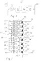
- FIG. 2 An exemplary construction of an inverter 15 is shown in FIG. 2.
- the inverter 15 of this example comprises 8 inverter bridges B1, which operate in parallel. , B8, which are each connected to the input lines 17, 18 coming from the DC voltage intermediate circuit 14 with a parallel capacitor C1, .., C8 at the input.
- a transformer 19 is provided, which contains a pair of windings for each of the inverter bridges B1, .., B8 from a primary winding P1, .., P8 and a secondary winding S1, .., S8 .
- the outputs of the inverter bridges B1, .., B8 are each connected to the corresponding primary windings P1, .., P8, the secondary windings S1, .., S8 are connected in series.
- the summed output signal is available on the output lines 20, 21.
- the transformer 19 can additionally be equipped with tertiary windings T1, .., T8, which are connected in series and are damped by a corresponding filter circuit 25 (see, for example, EP-B1-0 149 169).
- Exemplary permanently modulated and phase-shifted pulse series for the inverter bridges B1, .., B8 are shown in FIG. 3.
- the resulting sum voltage u Bi in FIG. 4 results from the summation of the individual pulse sequences in the transformer 19.
- the impedances 27 and 28 with the values z 1 and z 2 represent the transformer 19, the impedance 29 with the value z 3 represents the filter circuit 25.
- the rail network 16 can be represented in the equivalent circuit diagram by the impedance 30 (z 4 ) and the voltage source 31 describe.
- the equivalent circuit diagram of the VSC from FIG. 5 can be converted into an equivalent circuit diagram according to FIG. 6 by grounding (via the resistor 22) at the center tap 23 of the transformer 19.
- the impedances 27 and 28 of the transformer 19 are shown in FIG. 6 now divided into impedances 34 and 39 or 35 and 40, each with half the original impedance value, namely z 1/2 and z 2/2.
- the impedance 29 with the value z 3 is retained, while the impedance 30 and the voltage source 31 of the rail network 16 are also divided into the impedances 36 and 41 (each with the value z 4/2 ) or voltage sources 42 and 43.
- the center tap 23 of the transformer 19 is represented in FIG. 6 by the resistor 37 with the value R E.
- a corresponding resistor 38 with the value R E, r describes the total remote earthing resistance of the rail network 16.
- the equivalent circuit diagram of FIG. 6 can be broken down into two superimposed subsystems, namely the common mode system and the push-pull system (differential mode system). ). The two superimposed systems can then be treated separately from one another and the resulting currents and voltages can simply be added after the end of the analysis to obtain the real physical quantities.
- the equivalent circuit diagram in the common mode system for the upper half of the VSC is shown in FIG. 7.
- resistors 45 and 46 in the circuit, which each make up twice the grounding resistors 37 and 38, respectively.
- the voltage source 44 outputs a voltage u Bi, CM which drives a current i Bi, CM through the circuit.
- the equivalent circuit diagram in the push-pull system for the upper half of the VSC is shown in FIG. 8.
- the impedance 48 is also present here, which corresponds to half the impedance 29 and is characteristic of the filter circuit 25.
- the voltage source 47 outputs a voltage u Bi, D which drives a current i Bi, D through the circuit.
- the task is performed with an inverter of the type mentioned Art solved in that for damping or suppression of in-phase flowing over the earth connection Interference currents and the associated interference voltages in the earth connection switching means are arranged. Through the Arrangement of the switching means directly in the earth connection can be prevented that normally (when the switching means open-phase interference currents via the earth connection flow. In the event of a short circuit, the switching means can be closed so that the short-circuit currents flow to earth can.
- a first preferred embodiment of the invention draws is characterized in that the switching means as a saturation choke trained throttle include.
- the throttle represents the common mode currents with a suitable design have a high impedance without the ohmic connection of the center tap to affect the earth in the event of a fault. At the same time it is Choke as a passive component simple and safe in the Function.
- a simple throttle fulfills easily the demands placed on them.
- the choke is designed as a saturation choke, the Voltage-time area of the expected voltage-time area the interference voltages or interference currents in normal operation is adjusted.
- the saturation choke normally works below saturation and dampens that in the earth connection flowing currents. In the event of a short circuit, the saturation choke goes into saturation and then leaves largely unimpeded pass the short-circuit current.
- the switching means comprise a thyristor switch.
- the thyristor switch In normal operation, the thyristor switch is closed and thus reliably prevents the interference currents mentioned via the Earth connection can flow.
- the Thyristor switch In the event of a short circuit, the Thyristor switch, e.g. made of two anti-parallel thyristors exists, closed, and the short-circuit currents can be unhindered flow over the earth connection.
- An inverter according to the invention is preferred in one DC-link converter, in particular in a traction current converter or a frequency coupling.
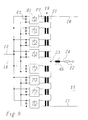
- FIG. 9 is a preferred embodiment for one Inverter reproduced according to the invention.
- the inverter of FIG. 9 is essentially the same in construction the inverter of Fig. 2.
- the tertiary windings on the transformer 19 and the associated filter circuit 25 are omitted here for the sake of simplicity.
- a resistor 22 leads to earth, is for damping or suppression of common mode currents in the earth connection one Saturation choke 49 provided in series with resistor 22.
- the characteristic of the saturation choke 49 is included dimensioned so that in normal (stationary) operation of the inverter 15, the expected in-phase Currents at the small number of 8 inverter bridges B1, .., B8 can be relatively high, strongly damped are, while in the event of a short circuit, the saturation choke 49 is controlled in the saturation and the short circuit current largely unhindered. This is the voltage-time area the saturation choke of the expected Voltage-time area of the interference voltages adjusted in normal operation.
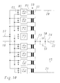
- the saturation choke 49 as a switching means, for example from two anti-parallel connected thyristors 50, 51 formed thyristor switch can be used, the Normally open and controlled in the event of a short circuit becomes.
- Example: With a transmitted nominal power of approx. 55MVA and a number of 8 inverter bridges without damping measures, there is a common mode current distortion (common mode currents), which accounts for approximately 3% of the nominal current (of approx. 400A). At a ground resistance 22 or 37 of R E 240 ⁇ , a maximum power loss of 100kW then drops. By inserting a saturation choke 49 with an unsaturated inductance of ⁇ 2H in the ground connection 24, the current distortion and thus the power loss dropping at the ground resistance can be reduced to ⁇ 5 kW.
- common mode current distortion common mode currents
- the invention is in Fig. 9, 10 in connection with a 1-phase Transformer has been explained. It goes without saying however, by itself that they are based on a 3-phase Transformer is applicable.
Landscapes
- Engineering & Computer Science (AREA)
- Power Engineering (AREA)
- Inverter Devices (AREA)
- Metal-Oxide And Bipolar Metal-Oxide Semiconductor Integrated Circuits (AREA)
- Bipolar Transistors (AREA)
- Confectionery (AREA)
- Glass Compositions (AREA)
- External Artificial Organs (AREA)
Applications Claiming Priority (2)
| Application Number | Priority Date | Filing Date | Title |
|---|---|---|---|
| DE19736612 | 1997-08-22 | ||
| DE19736612A DE19736612A1 (de) | 1997-08-22 | 1997-08-22 | Wechselrichter |
Publications (3)
| Publication Number | Publication Date |
|---|---|
| EP0903843A2 true EP0903843A2 (fr) | 1999-03-24 |
| EP0903843A3 EP0903843A3 (fr) | 1999-06-02 |
| EP0903843B1 EP0903843B1 (fr) | 2002-09-18 |
Family
ID=7839875
Family Applications (1)
| Application Number | Title | Priority Date | Filing Date |
|---|---|---|---|
| EP98810735A Expired - Lifetime EP0903843B1 (fr) | 1997-08-22 | 1998-07-30 | Onduleur |
Country Status (8)
| Country | Link |
|---|---|
| US (1) | US6169676B1 (fr) |
| EP (1) | EP0903843B1 (fr) |
| JP (1) | JPH11136956A (fr) |
| KR (1) | KR19990023779A (fr) |
| AT (1) | ATE224609T1 (fr) |
| DE (2) | DE19736612A1 (fr) |
| NO (1) | NO983808L (fr) |
| ZA (1) | ZA987063B (fr) |
Cited By (1)
| Publication number | Priority date | Publication date | Assignee | Title |
|---|---|---|---|---|
| DE102018109107B3 (de) | 2018-04-17 | 2019-05-23 | Sma Solar Technology Ag | Überwachungsvorrichtung und Verfahren zum Überwachen eines Solargenerators auf Erdfehler |
Families Citing this family (19)
| Publication number | Priority date | Publication date | Assignee | Title |
|---|---|---|---|---|
| JP4112930B2 (ja) * | 2002-09-04 | 2008-07-02 | 東芝三菱電機産業システム株式会社 | インバータ装置 |
| US20070230226A1 (en) * | 2003-11-25 | 2007-10-04 | Jih-Sheng Lai | Multilevel intelligent universal auto-transformer |
| US20070223258A1 (en) * | 2003-11-25 | 2007-09-27 | Jih-Sheng Lai | Multilevel converters for intelligent high-voltage transformers |
| US7050311B2 (en) * | 2003-11-25 | 2006-05-23 | Electric Power Research Institute, Inc. | Multilevel converter based intelligent universal transformer |
| US6954366B2 (en) * | 2003-11-25 | 2005-10-11 | Electric Power Research Institute | Multifunction hybrid intelligent universal transformer |
| TWI299616B (en) * | 2005-12-16 | 2008-08-01 | Via Tech Inc | Transmitter and transmission circuit |
| WO2007075132A1 (fr) * | 2005-12-28 | 2007-07-05 | Abb Research Ltd | Convertisseur de source de tension et son procede de commande |
| US7558092B2 (en) * | 2006-02-28 | 2009-07-07 | Tdk Corporation | Switching power supply unit |
| US8130518B2 (en) * | 2007-11-30 | 2012-03-06 | Rowan Technologies, Inc. | Multiphase grid synchronized regulated current source inverter systems |
| US9350166B2 (en) | 2010-10-05 | 2016-05-24 | Alencon Acquisition Co., Llc | High voltage energy harvesting and conversion renewable energy utility size electric power systems and visual monitoring and control systems for said systems |
| US8885371B2 (en) * | 2010-10-19 | 2014-11-11 | Astec International Limited | Multi-level parallel power converters |
| AU2012253314B2 (en) | 2011-05-12 | 2016-11-24 | Alencon Acquisition Co., Llc | High voltage energy harvesting and conversion renewable energy utility size electric power systems and visual monitoring and control systems |
| KR101491658B1 (ko) * | 2013-04-25 | 2015-02-09 | 주식회사 피에스텍 | 스위칭 증폭기 장치 및 그 제어 방법 |
| JP6148164B2 (ja) * | 2013-12-02 | 2017-06-14 | 東芝三菱電機産業システム株式会社 | 無停電電源システム |
| JP6014061B2 (ja) * | 2014-01-22 | 2016-10-25 | 東芝三菱電機産業システム株式会社 | 無停電電源システム |
| JP6331480B2 (ja) * | 2014-03-03 | 2018-05-30 | 株式会社リコー | インバータ装置及びプラズマ発生装置 |
| US10483759B2 (en) | 2016-04-07 | 2019-11-19 | Alencon Acquisition Co., Llc | Integrated multi-mode large-scale electric power support system for an electrical grid |
| EP3642946A1 (fr) * | 2017-06-21 | 2020-04-29 | ABB Schweiz AG | Régulation de courant basée sur un modèle d'un convertisseur de puissance trimonophasé |
| DE102019124568A1 (de) * | 2019-09-12 | 2021-03-18 | Tdk Electronics Ag | Verfahren zum Betreiben eines drahtlosen Ladegeräts und drahtloses Ladegerätsystem |
Family Cites Families (11)
| Publication number | Priority date | Publication date | Assignee | Title |
|---|---|---|---|---|
| US3671810A (en) | 1969-09-18 | 1972-06-20 | Singer Co | Saturated core transient current limiter |
| CH633918A5 (en) | 1978-04-10 | 1982-12-31 | Bbc Brown Boveri & Cie | Method for rapidly reducing the short-circuit current in a network, and a device for carrying out the method |
| DE3010099A1 (de) | 1980-02-25 | 1981-09-03 | BBC AG Brown, Boveri & Cie., Baden, Aargau | Elektronische schutzschaltung |
| CA1203007A (fr) * | 1983-07-06 | 1986-04-08 | Dale B. Williston | Dispositif de mise a la terre |
| DE3602496A1 (de) | 1986-01-28 | 1987-07-30 | Klein Kg Elektro Geraete G | Verfahren zum parallelbetrieb von wechselrichtern und wechselrichteranordnung zur durchfuehrung des verfahrens |
| US5065303A (en) | 1990-07-24 | 1991-11-12 | Sundstrand Corporation | Transformer-coupled and phase-shifted inverter |
| DE4142644C1 (fr) | 1991-12-21 | 1993-02-04 | Fraunhofer-Gesellschaft Zur Foerderung Der Angewandten Forschung Ev, 8000 Muenchen, De | |
| DE4225269A1 (de) * | 1992-07-31 | 1994-02-03 | Asea Brown Boveri | Verfahren zur Dämpfung von Netzoberschwingungen und eine Netzkupplung |
| US5508905A (en) | 1992-08-06 | 1996-04-16 | Metropolitan Pump Company | Low distortion variable output power supply |
| DE19736613A1 (de) * | 1997-08-22 | 1999-02-25 | Asea Brown Boveri | Wechselrichter |
| DE19736614A1 (de) * | 1997-08-22 | 1999-02-25 | Asea Brown Boveri | Wechselrichter |
-
1997
- 1997-08-22 DE DE19736612A patent/DE19736612A1/de not_active Withdrawn
-
1998
- 1998-07-30 DE DE59805592T patent/DE59805592D1/de not_active Expired - Fee Related
- 1998-07-30 AT AT98810735T patent/ATE224609T1/de not_active IP Right Cessation
- 1998-07-30 EP EP98810735A patent/EP0903843B1/fr not_active Expired - Lifetime
- 1998-08-06 ZA ZA987063A patent/ZA987063B/xx unknown
- 1998-08-19 NO NO983808A patent/NO983808L/no not_active Application Discontinuation
- 1998-08-20 JP JP10233393A patent/JPH11136956A/ja active Pending
- 1998-08-21 KR KR1019980033977A patent/KR19990023779A/ko not_active Withdrawn
- 1998-08-21 US US09/137,539 patent/US6169676B1/en not_active Expired - Fee Related
Cited By (1)
| Publication number | Priority date | Publication date | Assignee | Title |
|---|---|---|---|---|
| DE102018109107B3 (de) | 2018-04-17 | 2019-05-23 | Sma Solar Technology Ag | Überwachungsvorrichtung und Verfahren zum Überwachen eines Solargenerators auf Erdfehler |
Also Published As
| Publication number | Publication date |
|---|---|
| US6169676B1 (en) | 2001-01-02 |
| EP0903843B1 (fr) | 2002-09-18 |
| ZA987063B (en) | 1999-02-08 |
| NO983808L (no) | 1999-02-23 |
| EP0903843A3 (fr) | 1999-06-02 |
| KR19990023779A (ko) | 1999-03-25 |
| NO983808D0 (no) | 1998-08-19 |
| JPH11136956A (ja) | 1999-05-21 |
| DE19736612A1 (de) | 1999-02-25 |
| DE59805592D1 (de) | 2002-10-24 |
| ATE224609T1 (de) | 2002-10-15 |
Similar Documents
| Publication | Publication Date | Title |
|---|---|---|
| EP0903843B1 (fr) | Onduleur | |
| DE2950247C2 (de) | Stromversorgungssystem | |
| EP2217937B1 (fr) | Dispositif d'essai à haute tension de transformateurs | |
| EP0166954B1 (fr) | Procédé pour la réduction des surtensions dynamiques dans un réseau de courant alternatif | |
| DE102005012371A1 (de) | Zwölfpuls-Hochspannungsgleichstromübertagung | |
| EP0212172B1 (fr) | Procédé et dispositif de compensation d'oscillations de courant | |
| EP0898359A2 (fr) | Onduleur | |
| EP1069673B1 (fr) | Filtre réseau | |
| EP0682402B1 (fr) | Dispositif pour la limitation de la pente des grandeurs de sortie d'un convertisseur auto-commuté à circuit intermédiaire à tension continue | |
| EP0898358A2 (fr) | Onduleur | |
| EP3180844B1 (fr) | Ensemble convertisseur muni d'une unité de court-circuit ainsi que procédé de coupure d'une ligne à tension alternative | |
| CH642493A5 (de) | Uebertragungsanlage fuer hochgespannten gleichstrom. | |
| WO1999049559A2 (fr) | Procede et dispositif pour supprimer les parasites dans des changeurs de frequence | |
| WO2018113926A1 (fr) | Convertisseur | |
| DE4235223C1 (de) | Schaltungsanordnung zum Betreiben und gemeinsamen Bremsen von mehreren, kraftschlüssig über eine Last verbundenen, einzeln an Gleichspannungszwischenkreis-Umrichter angeschlossenen Drehstrommotoren | |
| DE102018208626A1 (de) | Magnetisch regelbare Drossel zur Blindleistungskompensation mit kapazitiv beschalteten Zusatzwicklungen | |
| DE1463574B1 (de) | Erdschlussschutzeinrichtung fuer galvanisch vom Netz getrennte Wechsel- oder Drehstromsysteme | |
| DE102004002261A1 (de) | Kommutierungsfilter | |
| EP3827510B1 (fr) | Onduleur de fréquence à pré-commutation simplifiée | |
| DE4025685A1 (de) | Stromrichterschaltung | |
| WO1991003861A1 (fr) | Circuit pour convertisseur commande | |
| DE3938700C2 (fr) | ||
| DE10221933A1 (de) | Schaltungsanordnung für einen Gleichspannungszwischenkreis | |
| DE588301C (de) | Schutzschaltung zur selbsttaetigen Steuerung der Schalter einer Leitungsstrecke | |
| DE9408504U1 (de) | Frequenzumrichter |
Legal Events
| Date | Code | Title | Description |
|---|---|---|---|
| PUAI | Public reference made under article 153(3) epc to a published international application that has entered the european phase |
Free format text: ORIGINAL CODE: 0009012 |
|
| AK | Designated contracting states |
Kind code of ref document: A2 Designated state(s): AT CH DE LI SE |
|
| AX | Request for extension of the european patent |
Free format text: AL;LT;LV;MK;RO;SI |
|
| PUAL | Search report despatched |
Free format text: ORIGINAL CODE: 0009013 |
|
| AK | Designated contracting states |
Kind code of ref document: A3 Designated state(s): AT BE CH CY DE DK ES FI FR GB GR IE IT LI LU MC NL PT SE |
|
| AX | Request for extension of the european patent |
Free format text: AL;LT;LV;MK;RO;SI |
|
| 17P | Request for examination filed |
Effective date: 19991108 |
|
| AKX | Designation fees paid |
Free format text: AT CH DE LI SE |
|
| 17Q | First examination report despatched |
Effective date: 20000314 |
|
| RAP1 | Party data changed (applicant data changed or rights of an application transferred) |
Owner name: ABB INDUSTRIE AG |
|
| GRAG | Despatch of communication of intention to grant |
Free format text: ORIGINAL CODE: EPIDOS AGRA |
|
| GRAG | Despatch of communication of intention to grant |
Free format text: ORIGINAL CODE: EPIDOS AGRA |
|
| GRAH | Despatch of communication of intention to grant a patent |
Free format text: ORIGINAL CODE: EPIDOS IGRA |
|
| RAP1 | Party data changed (applicant data changed or rights of an application transferred) |
Owner name: ABB SCHWEIZ AG |
|
| GRAH | Despatch of communication of intention to grant a patent |
Free format text: ORIGINAL CODE: EPIDOS IGRA |
|
| GRAA | (expected) grant |
Free format text: ORIGINAL CODE: 0009210 |
|
| AK | Designated contracting states |
Kind code of ref document: B1 Designated state(s): AT CH DE LI SE |
|
| REF | Corresponds to: |
Ref document number: 224609 Country of ref document: AT Date of ref document: 20021015 Kind code of ref document: T |
|
| REG | Reference to a national code |
Ref country code: CH Ref legal event code: EP |
|
| REF | Corresponds to: |
Ref document number: 59805592 Country of ref document: DE Date of ref document: 20021024 |
|
| REG | Reference to a national code |
Ref country code: CH Ref legal event code: NV Representative=s name: ABB BUSINESS SERVICES LTD INTELLECTUAL PROPERTY (S |
|
| PLBE | No opposition filed within time limit |
Free format text: ORIGINAL CODE: 0009261 |
|
| STAA | Information on the status of an ep patent application or granted ep patent |
Free format text: STATUS: NO OPPOSITION FILED WITHIN TIME LIMIT |
|
| PG25 | Lapsed in a contracting state [announced via postgrant information from national office to epo] |
Ref country code: AT Free format text: LAPSE BECAUSE OF NON-PAYMENT OF DUE FEES Effective date: 20030730 |
|
| PG25 | Lapsed in a contracting state [announced via postgrant information from national office to epo] |
Ref country code: SE Free format text: LAPSE BECAUSE OF NON-PAYMENT OF DUE FEES Effective date: 20030731 Ref country code: LI Free format text: LAPSE BECAUSE OF NON-PAYMENT OF DUE FEES Effective date: 20030731 Ref country code: CH Free format text: LAPSE BECAUSE OF NON-PAYMENT OF DUE FEES Effective date: 20030731 |
|
| 26N | No opposition filed |
Effective date: 20030619 |
|
| PG25 | Lapsed in a contracting state [announced via postgrant information from national office to epo] |
Ref country code: DE Free format text: LAPSE BECAUSE OF NON-PAYMENT OF DUE FEES Effective date: 20040203 |
|
| EUG | Se: european patent has lapsed | ||
| REG | Reference to a national code |
Ref country code: CH Ref legal event code: PL |