EP0898359A2 - Onduleur - Google Patents
Onduleur Download PDFInfo
- Publication number
- EP0898359A2 EP0898359A2 EP98810736A EP98810736A EP0898359A2 EP 0898359 A2 EP0898359 A2 EP 0898359A2 EP 98810736 A EP98810736 A EP 98810736A EP 98810736 A EP98810736 A EP 98810736A EP 0898359 A2 EP0898359 A2 EP 0898359A2
- Authority
- EP
- European Patent Office
- Prior art keywords
- inverter
- output
- secondary windings
- transformer
- series connection
- Prior art date
- Legal status (The legal status is an assumption and is not a legal conclusion. Google has not performed a legal analysis and makes no representation as to the accuracy of the status listed.)
- Withdrawn
Links
Images


Classifications
-
- H—ELECTRICITY
- H02—GENERATION; CONVERSION OR DISTRIBUTION OF ELECTRIC POWER
- H02M—APPARATUS FOR CONVERSION BETWEEN AC AND AC, BETWEEN AC AND DC, OR BETWEEN DC AND DC, AND FOR USE WITH MAINS OR SIMILAR POWER SUPPLY SYSTEMS; CONVERSION OF DC OR AC INPUT POWER INTO SURGE OUTPUT POWER; CONTROL OR REGULATION THEREOF
- H02M7/00—Conversion of ac power input into dc power output; Conversion of dc power input into ac power output
- H02M7/42—Conversion of dc power input into ac power output without possibility of reversal
- H02M7/44—Conversion of dc power input into ac power output without possibility of reversal by static converters
- H02M7/48—Conversion of dc power input into ac power output without possibility of reversal by static converters using discharge tubes with control electrode or semiconductor devices with control electrode
- H02M7/483—Converters with outputs that each can have more than two voltages levels
- H02M7/49—Combination of the output voltage waveforms of a plurality of converters
-
- H—ELECTRICITY
- H02—GENERATION; CONVERSION OR DISTRIBUTION OF ELECTRIC POWER
- H02M—APPARATUS FOR CONVERSION BETWEEN AC AND AC, BETWEEN AC AND DC, OR BETWEEN DC AND DC, AND FOR USE WITH MAINS OR SIMILAR POWER SUPPLY SYSTEMS; CONVERSION OF DC OR AC INPUT POWER INTO SURGE OUTPUT POWER; CONTROL OR REGULATION THEREOF
- H02M7/00—Conversion of ac power input into dc power output; Conversion of dc power input into ac power output
- H02M7/42—Conversion of dc power input into ac power output without possibility of reversal
- H02M7/44—Conversion of dc power input into ac power output without possibility of reversal by static converters
- H02M7/48—Conversion of dc power input into ac power output without possibility of reversal by static converters using discharge tubes with control electrode or semiconductor devices with control electrode
- H02M7/505—Conversion of dc power input into ac power output without possibility of reversal by static converters using discharge tubes with control electrode or semiconductor devices with control electrode using devices of a thyratron or thyristor type requiring extinguishing means
- H02M7/515—Conversion of dc power input into ac power output without possibility of reversal by static converters using discharge tubes with control electrode or semiconductor devices with control electrode using devices of a thyratron or thyristor type requiring extinguishing means using semiconductor devices only
- H02M7/521—Conversion of dc power input into ac power output without possibility of reversal by static converters using discharge tubes with control electrode or semiconductor devices with control electrode using devices of a thyratron or thyristor type requiring extinguishing means using semiconductor devices only in a bridge configuration
-
- H—ELECTRICITY
- H02—GENERATION; CONVERSION OR DISTRIBUTION OF ELECTRIC POWER
- H02M—APPARATUS FOR CONVERSION BETWEEN AC AND AC, BETWEEN AC AND DC, OR BETWEEN DC AND DC, AND FOR USE WITH MAINS OR SIMILAR POWER SUPPLY SYSTEMS; CONVERSION OF DC OR AC INPUT POWER INTO SURGE OUTPUT POWER; CONTROL OR REGULATION THEREOF
- H02M7/00—Conversion of ac power input into dc power output; Conversion of dc power input into ac power output
- H02M7/42—Conversion of dc power input into ac power output without possibility of reversal
- H02M7/44—Conversion of dc power input into ac power output without possibility of reversal by static converters
- H02M7/48—Conversion of dc power input into ac power output without possibility of reversal by static converters using discharge tubes with control electrode or semiconductor devices with control electrode
Definitions
- the present invention relates to the field of Power electronics. It relates to an inverter, comprehensively a plurality of from the same DC voltage source parallel working inverter bridges, their Output voltages are summed up via a transformer, which corresponds to the number of inverter bridges Number of primary windings and associated secondary windings each inverter bridge each connected to a primary winding on the output side and the secondary windings for the summation of the output voltages are connected in series, and the inverter bridges in accordance with an auxiliary control voltage pulse duration modulated and the auxiliary control voltages of the individual inverter bridges with each other have a constant phase difference, and wherein the Transformer has a center tap, which has a Earth connection is earthed.
- traction current converter 10 for example a (thyristor-equipped) Power converter 13
- the three-phase current via a transformer 12 decreases from the three-phase network 11 and into a direct current converts a DC link 14 to Smoothing or temporary storage, and an inverter 15, which turns the direct current back into an alternating current of the desired Frequency converted and fed into the rail network 16.
- inverter 15 parallel inverter bridges with switchable Valves (e.g. GTOs) are used, which are controlled by pulse duration modulation and the desired sinusoidal output voltage through a sequence of permanently modulated rectangular pulses Approximate alternating polarity.
- switchable Valves e.g. GTOs
- pulse duration modulation usually becomes a triangular auxiliary control voltage used.
- Details of the control can, for example a special print (No. 9608-1000-0) by the applicant, "Fully static 100 MW frequency coupling Bremen", taken become. If several inverter bridges are operated in parallel, the output voltages are added up. A decrease the harmonic content is achieved by that the control of the individual inverter bridges via the auxiliary control voltages out of phase.
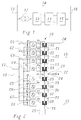
- FIG. 2 An exemplary construction of an inverter 15 is shown in FIG. 2.
- the inverter 15 of this example comprises 8 inverter bridges B1, .., B8 operating in parallel, each of which is connected to the input lines 17, 18 coming from the DC voltage intermediate circuit 14 with a parallel capacitor C1, .., C8.
- a transformer 19 is provided, which contains a pair of windings for each of the inverter bridges B1, .., B8 from a primary winding P1, .., P8 and a secondary winding S1, .., S8 .
- the outputs of the inverter bridges B1, .., B8 are each connected to the corresponding primary windings P1, .., P8, the secondary windings S1, .., S8 are connected in series.
- the summed output signal is available on the output lines 20, 21.
- the transformer 19 can additionally be equipped with tertiary windings T1, .., T8, which are connected in series and are damped by a corresponding filter circuit 25 (see, for example, EP-B1-0 149 169).
- Exemplary permanently modulated and phase-shifted pulse series for the inverter bridges B1, .., B8 are shown in FIG. 3.
- the resulting sum voltage u Bi in FIG. 4 results from the summation of the individual pulse sequences in the transformer 19.
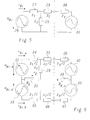
- the impedances 27 and 28 with the values z 1 and z 2 represent the transformer 19, the impedance 29 with the value z 3 represents the filter circuit 25.
- the rail network 16 can be represented in the equivalent circuit diagram by the impedance 30 (z 4 ) and the voltage source 31 describe.
- the equivalent circuit diagram of the VSC from FIG. 5 can be converted into an equivalent circuit diagram according to FIG. 6 by grounding (via the resistor 22) at the center tap 23 of the transformer 19.
- the impedances 27 and 28 of the transformer 19 are shown in FIG. 6 now divided into impedances 34 and 39 or 35 and 40, each with half the original impedance value, namely z 1/2 and z 2/2.
- the impedance 29 with the value z3 is maintained, while the impedance 30 and the voltage source 31 to the rail system 16 is also divided in the impedances 36 and 41 (in each case with the value z 4/2) or voltage sources 42 and 43.
- the grounding via the center tap 23 of the transformer 19 is represented in FIG. 6 by the resistor 37 with the value R E.
- a corresponding resistor 38 with the value R E, r describes the total remote earthing resistance of the rail network 16.
- the equivalent circuit diagram of FIG. 6 can be broken down into two superimposed subsystems, namely the common mode system and the push-pull system (differential mode system). ). The two superimposed systems can then be treated separately from one another and the resulting currents and voltages can simply be added after the end of the analysis to obtain the real physical quantities.
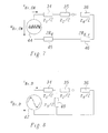
- the equivalent circuit diagram in the common mode system for the upper half of the VSC is shown in FIG. 7.
- resistors 45 and 46 in the circuit, which each make up twice the grounding resistors 37 and 38, respectively.
- the voltage source 44 outputs a voltage u Bi, CM which drives a current i Bi, CM through the circuit.
- the equivalent circuit diagram in the push-pull system for the upper half of the VSC is shown in FIG. 8.
- the impedance 48 is also present here, which corresponds to half the impedance 29 and is characteristic of the filter circuit 25.
- the voltage source 47 outputs a voltage u Bi, D which drives a current i Bi, D through the circuit.
- the object is achieved in an inverter of the type mentioned at the outset in that for damping or suppression of in-phase or common-mode interference currents flowing via the ground connection within the transformer, the secondary windings are each divided into a first and second similar partial-secondary winding, and that Partial secondary windings are connected to one another and to the center tap in such a way that the common mode voltages induced in the partial secondary windings cancel each other out.
- the particular advantage of the solution according to the invention is that common-mode voltage components u Bi, CM or common-mode current components are avoided without the spectral quality of the push-pull voltage u Bi, D or the push-pull currents being impaired in any way.
- a preferred embodiment of the invention stands out characterized in that the first partial secondary windings a first Series connection that form the second part-secondary windings a second parallel to the first series connection Series connection form that the top output of the first Series connection that forms an output of the inverter and the lower output of the second series connection the other Output of the inverter forms, and that the lower Output of the first series connection and the upper output of the second series connection merged at the center tap are.
- An inverter according to the invention is preferred in one Converter with DC link, especially in a traction current converter or a frequency coupling.
- FIG. 9 is a preferred embodiment for one Inverter reproduced according to the invention.
- the inverter of FIG. 9 is essentially the same in construction the inverter of FIG. 2.
- the secondary windings in the transformer 19 divided into two Similar secondary windings S11, S12; ...; S81, S82.
- the first (upper) partial secondary windings S11, .., S81 are connected in series and form a first series connection with the outputs A1 (top) and A3 (below).
- the second (lower) partial secondary windings S12, .., S82 are also connected in series and form a parallel to the first series connection second series connection with the outputs A2 (top) and A4 (below).
Landscapes
- Engineering & Computer Science (AREA)
- Power Engineering (AREA)
- Inverter Devices (AREA)
- Amplifiers (AREA)
- Confectionery (AREA)
- Coils Or Transformers For Communication (AREA)
Applications Claiming Priority (2)
| Application Number | Priority Date | Filing Date | Title |
|---|---|---|---|
| DE19736613 | 1997-08-22 | ||
| DE19736613A DE19736613A1 (de) | 1997-08-22 | 1997-08-22 | Wechselrichter |
Publications (2)
| Publication Number | Publication Date |
|---|---|
| EP0898359A2 true EP0898359A2 (fr) | 1999-02-24 |
| EP0898359A3 EP0898359A3 (fr) | 1999-10-20 |
Family
ID=7839876
Family Applications (1)
| Application Number | Title | Priority Date | Filing Date |
|---|---|---|---|
| EP98810736A Withdrawn EP0898359A3 (fr) | 1997-08-22 | 1998-07-30 | Onduleur |
Country Status (6)
| Country | Link |
|---|---|
| US (1) | US5999428A (fr) |
| EP (1) | EP0898359A3 (fr) |
| KR (1) | KR19990023780A (fr) |
| DE (1) | DE19736613A1 (fr) |
| NO (1) | NO983809L (fr) |
| ZA (1) | ZA987064B (fr) |
Cited By (2)
| Publication number | Priority date | Publication date | Assignee | Title |
|---|---|---|---|---|
| WO2004064240A1 (fr) | 2003-01-15 | 2004-07-29 | Siemens Aktiengesellschaft | Procede pour reduire les courants parasites en mode commun dans un systeme d'entrainement electrique, et systeme d'entrainement electrique correspondant |
| CN104852387A (zh) * | 2015-05-11 | 2015-08-19 | 西南交通大学 | 一种基于模块化级联h桥的有源补偿同相供电系统 |
Families Citing this family (11)
| Publication number | Priority date | Publication date | Assignee | Title |
|---|---|---|---|---|
| DE19736612A1 (de) * | 1997-08-22 | 1999-02-25 | Asea Brown Boveri | Wechselrichter |
| GB2330254B (en) * | 1997-10-09 | 2000-10-18 | Toshiba Kk | Multiple inverter system |
| US6377478B1 (en) | 1999-05-28 | 2002-04-23 | Toshiba International Corporation | Inverter device |
| GB2354121B (en) * | 1999-09-09 | 2001-07-25 | Donald Watson Bingley | Improvements in or relating to inverters |
| EP1195877B1 (fr) * | 2000-10-06 | 2018-09-12 | ABB Schweiz AG | Système d'onduleur avec modules onduleurs connectés par circuit intermédiaire à tension continue et procédé de fonctionnement |
| JP4112930B2 (ja) * | 2002-09-04 | 2008-07-02 | 東芝三菱電機産業システム株式会社 | インバータ装置 |
| ES2715978T3 (es) * | 2008-09-12 | 2019-06-07 | Vestas Wind Sys As | Filtro de armónicos de baja tensión para sistemas convertidores de escala completa |
| ES2411356T3 (es) * | 2009-05-07 | 2013-07-05 | Siemens Aktiengesellschaft | Método para adaptar una configuración de un dispositivo de conversión de tensión y una unidad de conversión de tensión para un dispositivo de conversión de tensión |
| ES2402462B1 (es) * | 2010-11-08 | 2014-03-28 | Ingeteam Technology, S.A | Método de control para la conversión de energía, y convertidor electrónico de potencia adaptado para llevar a cabo dicho método |
| RU2515474C2 (ru) * | 2011-05-17 | 2014-05-10 | Хонда Мотор Ко., Лтд. | Инверторный генератор |
| CN110771019B (zh) * | 2017-06-21 | 2021-10-19 | Abb电网瑞士股份公司 | 三相-单相功率变流器的基于模型的电流控制 |
Citations (5)
| Publication number | Priority date | Publication date | Assignee | Title |
|---|---|---|---|---|
| US2779926A (en) * | 1954-01-25 | 1957-01-29 | Gen Electric | Transformer with five-leg core |
| US3611224A (en) * | 1967-08-24 | 1971-10-05 | Licentia Gmbh | Controllable reactive current generator |
| US3628123A (en) * | 1970-03-11 | 1971-12-14 | Westinghouse Electric Corp | Apparatus for harmonic neutralization of inverters |
| US5006783A (en) * | 1989-10-16 | 1991-04-09 | General Signal Corporation | Three phase voltage regulator system using tertiary winding transformer |
| US5057808A (en) * | 1989-12-27 | 1991-10-15 | Sundstrand Corporation | Transformer with voltage balancing tertiary winding |
Family Cites Families (5)
| Publication number | Priority date | Publication date | Assignee | Title |
|---|---|---|---|---|
| US4159513A (en) * | 1977-09-30 | 1979-06-26 | Westinghouse Electric Corp. | Static controlled AC motor drive having plug reversal capability |
| US4426678A (en) * | 1982-05-28 | 1984-01-17 | The United States Of America As Represented By The Administrator Of The National Aeronautics And Space Administration | D.C. to D.C. converter |
| DE3602496A1 (de) * | 1986-01-28 | 1987-07-30 | Klein Kg Elektro Geraete G | Verfahren zum parallelbetrieb von wechselrichtern und wechselrichteranordnung zur durchfuehrung des verfahrens |
| US5065303A (en) * | 1990-07-24 | 1991-11-12 | Sundstrand Corporation | Transformer-coupled and phase-shifted inverter |
| US5508905A (en) * | 1992-08-06 | 1996-04-16 | Metropolitan Pump Company | Low distortion variable output power supply |
-
1997
- 1997-08-22 DE DE19736613A patent/DE19736613A1/de not_active Withdrawn
-
1998
- 1998-07-30 EP EP98810736A patent/EP0898359A3/fr not_active Withdrawn
- 1998-08-06 ZA ZA987064A patent/ZA987064B/xx unknown
- 1998-08-19 NO NO983809A patent/NO983809L/no not_active Application Discontinuation
- 1998-08-21 KR KR1019980033978A patent/KR19990023780A/ko not_active Application Discontinuation
- 1998-08-21 US US09/137,746 patent/US5999428A/en not_active Expired - Fee Related
Patent Citations (5)
| Publication number | Priority date | Publication date | Assignee | Title |
|---|---|---|---|---|
| US2779926A (en) * | 1954-01-25 | 1957-01-29 | Gen Electric | Transformer with five-leg core |
| US3611224A (en) * | 1967-08-24 | 1971-10-05 | Licentia Gmbh | Controllable reactive current generator |
| US3628123A (en) * | 1970-03-11 | 1971-12-14 | Westinghouse Electric Corp | Apparatus for harmonic neutralization of inverters |
| US5006783A (en) * | 1989-10-16 | 1991-04-09 | General Signal Corporation | Three phase voltage regulator system using tertiary winding transformer |
| US5057808A (en) * | 1989-12-27 | 1991-10-15 | Sundstrand Corporation | Transformer with voltage balancing tertiary winding |
Cited By (4)
| Publication number | Priority date | Publication date | Assignee | Title |
|---|---|---|---|---|
| WO2004064240A1 (fr) | 2003-01-15 | 2004-07-29 | Siemens Aktiengesellschaft | Procede pour reduire les courants parasites en mode commun dans un systeme d'entrainement electrique, et systeme d'entrainement electrique correspondant |
| KR101144364B1 (ko) | 2003-01-15 | 2012-05-11 | 지멘스 악티엔게젤샤프트 | 전기 추진 시스템의 공통 모드 간섭전류를 감소시키기 위한방법 및 이에 상응하는 전기 추진 시스템 |
| CN104852387A (zh) * | 2015-05-11 | 2015-08-19 | 西南交通大学 | 一种基于模块化级联h桥的有源补偿同相供电系统 |
| CN104852387B (zh) * | 2015-05-11 | 2017-06-13 | 西南交通大学 | 一种基于模块化级联h桥的有源补偿同相供电系统 |
Also Published As
| Publication number | Publication date |
|---|---|
| KR19990023780A (ko) | 1999-03-25 |
| ZA987064B (en) | 1999-02-08 |
| US5999428A (en) | 1999-12-07 |
| DE19736613A1 (de) | 1999-02-25 |
| EP0898359A3 (fr) | 1999-10-20 |
| NO983809D0 (no) | 1998-08-19 |
| NO983809L (no) | 1999-02-23 |
Similar Documents
| Publication | Publication Date | Title |
|---|---|---|
| EP0903843B1 (fr) | Onduleur | |
| EP0899859B1 (fr) | Onduleur avec circuit intermédiaire de tension | |
| DE102005012371A1 (de) | Zwölfpuls-Hochspannungsgleichstromübertagung | |
| EP0898359A2 (fr) | Onduleur | |
| DE19913634C2 (de) | Vorrichtung zur Steuerung abschaltbarer Halbleiterschalter eines netzseitigen Stromrichters eines Spannungszwischenkreis-Umrichters | |
| DE10128152B4 (de) | Schiffsantriebssystem mit vermindertem Bordnetzklirrfaktor | |
| DE102007047165A1 (de) | Energieversorgung | |
| EP0212172B1 (fr) | Procédé et dispositif de compensation d'oscillations de courant | |
| EP0898358A2 (fr) | Onduleur | |
| EP0682402B1 (fr) | Dispositif pour la limitation de la pente des grandeurs de sortie d'un convertisseur auto-commuté à circuit intermédiaire à tension continue | |
| DE69125894T2 (de) | Optimiertes 18-Puls AC/DC, oder DC/AC, Konvertersystem | |
| CH641610A5 (de) | Rundsteueranlage. | |
| CH642493A5 (de) | Uebertragungsanlage fuer hochgespannten gleichstrom. | |
| EP0115814B1 (fr) | Dispositif pour alimenter des signaux à fréquence acoustique dans un réseau de distribution d'énergie électrique | |
| EP0584660B1 (fr) | Méthode et dispositif de circuit pour la réduction des harmoniques | |
| DE102004002261A1 (de) | Kommutierungsfilter | |
| DE102018208626A1 (de) | Magnetisch regelbare Drossel zur Blindleistungskompensation mit kapazitiv beschalteten Zusatzwicklungen | |
| EP3827510B1 (fr) | Onduleur de fréquence à pré-commutation simplifiée | |
| EP0967109A1 (fr) | Sous-station pour l'alimentation de deux sections d'un réseau électrifié de chemin de fer | |
| DE4025685A1 (de) | Stromrichterschaltung | |
| EP0763833A2 (fr) | Transformateur pour un véhicule à propulsion électrique | |
| DE3045574A1 (de) | Statischer blindleistungskompensator | |
| DE329364C (de) | Transformator mit m Magnetschenkeln zur Veraenderung der Phasenzahl n eines Mehrphasensystems | |
| DE9408504U1 (de) | Frequenzumrichter | |
| DE19646085A1 (de) | Stromrichterschaltungsanordnung |
Legal Events
| Date | Code | Title | Description |
|---|---|---|---|
| PUAI | Public reference made under article 153(3) epc to a published international application that has entered the european phase |
Free format text: ORIGINAL CODE: 0009012 |
|
| AK | Designated contracting states |
Kind code of ref document: A2 Designated state(s): AT CH DE LI SE |
|
| AX | Request for extension of the european patent |
Free format text: AL;LT;LV;MK;RO;SI |
|
| PUAL | Search report despatched |
Free format text: ORIGINAL CODE: 0009013 |
|
| AK | Designated contracting states |
Kind code of ref document: A3 Designated state(s): AT BE CH CY DE DK ES FI FR GB GR IE IT LI LU MC NL PT SE |
|
| AX | Request for extension of the european patent |
Free format text: AL;LT;LV;MK;RO;SI |
|
| 17P | Request for examination filed |
Effective date: 20000318 |
|
| RAP1 | Party data changed (applicant data changed or rights of an application transferred) |
Owner name: ABB AG (ABB SA) (ABB LTD) |
|
| RAP1 | Party data changed (applicant data changed or rights of an application transferred) |
Owner name: ABB (SCHWEIZ) AG |
|
| AKX | Designation fees paid |
Free format text: AT CH DE LI SE |
|
| RAP1 | Party data changed (applicant data changed or rights of an application transferred) |
Owner name: ABB INDUSTRIE AG |
|
| RAP1 | Party data changed (applicant data changed or rights of an application transferred) |
Owner name: ABB SCHWEIZ AG |
|
| STAA | Information on the status of an ep patent application or granted ep patent |
Free format text: STATUS: THE APPLICATION HAS BEEN WITHDRAWN |
|
| 18W | Application withdrawn |
Effective date: 20030303 |