EP0903843A2 - Inverter - Google Patents
Inverter Download PDFInfo
- Publication number
- EP0903843A2 EP0903843A2 EP98810735A EP98810735A EP0903843A2 EP 0903843 A2 EP0903843 A2 EP 0903843A2 EP 98810735 A EP98810735 A EP 98810735A EP 98810735 A EP98810735 A EP 98810735A EP 0903843 A2 EP0903843 A2 EP 0903843A2
- Authority
- EP
- European Patent Office
- Prior art keywords
- inverter
- bridges
- earth connection
- voltages
- voltage
- Prior art date
- Legal status (The legal status is an assumption and is not a legal conclusion. Google has not performed a legal analysis and makes no representation as to the accuracy of the status listed.)
- Granted
Links
Images


Classifications
-
- H—ELECTRICITY
- H02—GENERATION; CONVERSION OR DISTRIBUTION OF ELECTRIC POWER
- H02M—APPARATUS FOR CONVERSION BETWEEN AC AND AC, BETWEEN AC AND DC, OR BETWEEN DC AND DC, AND FOR USE WITH MAINS OR SIMILAR POWER SUPPLY SYSTEMS; CONVERSION OF DC OR AC INPUT POWER INTO SURGE OUTPUT POWER; CONTROL OR REGULATION THEREOF
- H02M7/00—Conversion of ac power input into dc power output; Conversion of dc power input into ac power output
- H02M7/42—Conversion of dc power input into ac power output without possibility of reversal
- H02M7/44—Conversion of dc power input into ac power output without possibility of reversal by static converters
- H02M7/48—Conversion of dc power input into ac power output without possibility of reversal by static converters using discharge tubes with control electrode or semiconductor devices with control electrode
- H02M7/505—Conversion of dc power input into ac power output without possibility of reversal by static converters using discharge tubes with control electrode or semiconductor devices with control electrode using devices of a thyratron or thyristor type requiring extinguishing means
- H02M7/515—Conversion of dc power input into ac power output without possibility of reversal by static converters using discharge tubes with control electrode or semiconductor devices with control electrode using devices of a thyratron or thyristor type requiring extinguishing means using semiconductor devices only
- H02M7/521—Conversion of dc power input into ac power output without possibility of reversal by static converters using discharge tubes with control electrode or semiconductor devices with control electrode using devices of a thyratron or thyristor type requiring extinguishing means using semiconductor devices only in a bridge configuration
-
- H—ELECTRICITY
- H02—GENERATION; CONVERSION OR DISTRIBUTION OF ELECTRIC POWER
- H02M—APPARATUS FOR CONVERSION BETWEEN AC AND AC, BETWEEN AC AND DC, OR BETWEEN DC AND DC, AND FOR USE WITH MAINS OR SIMILAR POWER SUPPLY SYSTEMS; CONVERSION OF DC OR AC INPUT POWER INTO SURGE OUTPUT POWER; CONTROL OR REGULATION THEREOF
- H02M7/00—Conversion of ac power input into dc power output; Conversion of dc power input into ac power output
- H02M7/42—Conversion of dc power input into ac power output without possibility of reversal
- H02M7/44—Conversion of dc power input into ac power output without possibility of reversal by static converters
- H02M7/48—Conversion of dc power input into ac power output without possibility of reversal by static converters using discharge tubes with control electrode or semiconductor devices with control electrode
- H02M7/483—Converters with outputs that each can have more than two voltages levels
- H02M7/49—Combination of the output voltage waveforms of a plurality of converters
-
- H—ELECTRICITY
- H02—GENERATION; CONVERSION OR DISTRIBUTION OF ELECTRIC POWER
- H02M—APPARATUS FOR CONVERSION BETWEEN AC AND AC, BETWEEN AC AND DC, OR BETWEEN DC AND DC, AND FOR USE WITH MAINS OR SIMILAR POWER SUPPLY SYSTEMS; CONVERSION OF DC OR AC INPUT POWER INTO SURGE OUTPUT POWER; CONTROL OR REGULATION THEREOF
- H02M7/00—Conversion of ac power input into dc power output; Conversion of dc power input into ac power output
- H02M7/42—Conversion of dc power input into ac power output without possibility of reversal
- H02M7/44—Conversion of dc power input into ac power output without possibility of reversal by static converters
- H02M7/48—Conversion of dc power input into ac power output without possibility of reversal by static converters using discharge tubes with control electrode or semiconductor devices with control electrode
Definitions
- the present invention relates to the field of Power electronics. It relates to an inverter, comprehensively a plurality of on the same DC link parallel working inverter bridges, their Output voltages are summed up by summation means, where the inverter bridges according to a Carrier signal can be controlled and the pulse duration modulated Carrier signals between the individual inverter bridges have a constant phase difference, and wherein the Summation means have a center tap, which over an earth connection is earthed.
- traction current converter 10 for example a (thyristor-equipped) Power converter 13
- the three-phase current via a transformer 12 decreases from the three-phase network 11 and into a direct current converts a DC link 14 to Smoothing or temporary storage, and an inverter 15, which turns the direct current back into an alternating current of the desired Frequency converted and fed into the rail network 16.
- inverter 15 parallel inverter bridges with switchable Valves (e.g. GTOs) are used, which are controlled by pulse duration modulation and the desired sinusoidal output voltage through a sequence of permanently modulated rectangular pulses Approximate alternating polarity.
- GTOs switchable Valves
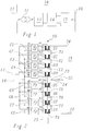
- FIG. 2 An exemplary construction of an inverter 15 is shown in FIG. 2.
- the inverter 15 of this example comprises 8 inverter bridges B1, which operate in parallel. , B8, which are each connected to the input lines 17, 18 coming from the DC voltage intermediate circuit 14 with a parallel capacitor C1, .., C8 at the input.
- a transformer 19 is provided, which contains a pair of windings for each of the inverter bridges B1, .., B8 from a primary winding P1, .., P8 and a secondary winding S1, .., S8 .
- the outputs of the inverter bridges B1, .., B8 are each connected to the corresponding primary windings P1, .., P8, the secondary windings S1, .., S8 are connected in series.
- the summed output signal is available on the output lines 20, 21.
- the transformer 19 can additionally be equipped with tertiary windings T1, .., T8, which are connected in series and are damped by a corresponding filter circuit 25 (see, for example, EP-B1-0 149 169).
- Exemplary permanently modulated and phase-shifted pulse series for the inverter bridges B1, .., B8 are shown in FIG. 3.
- the resulting sum voltage u Bi in FIG. 4 results from the summation of the individual pulse sequences in the transformer 19.
- the impedances 27 and 28 with the values z 1 and z 2 represent the transformer 19, the impedance 29 with the value z 3 represents the filter circuit 25.
- the rail network 16 can be represented in the equivalent circuit diagram by the impedance 30 (z 4 ) and the voltage source 31 describe.
- the equivalent circuit diagram of the VSC from FIG. 5 can be converted into an equivalent circuit diagram according to FIG. 6 by grounding (via the resistor 22) at the center tap 23 of the transformer 19.
- the impedances 27 and 28 of the transformer 19 are shown in FIG. 6 now divided into impedances 34 and 39 or 35 and 40, each with half the original impedance value, namely z 1/2 and z 2/2.
- the impedance 29 with the value z 3 is retained, while the impedance 30 and the voltage source 31 of the rail network 16 are also divided into the impedances 36 and 41 (each with the value z 4/2 ) or voltage sources 42 and 43.
- the center tap 23 of the transformer 19 is represented in FIG. 6 by the resistor 37 with the value R E.
- a corresponding resistor 38 with the value R E, r describes the total remote earthing resistance of the rail network 16.
- the equivalent circuit diagram of FIG. 6 can be broken down into two superimposed subsystems, namely the common mode system and the push-pull system (differential mode system). ). The two superimposed systems can then be treated separately from one another and the resulting currents and voltages can simply be added after the end of the analysis to obtain the real physical quantities.
- the equivalent circuit diagram in the common mode system for the upper half of the VSC is shown in FIG. 7.
- resistors 45 and 46 in the circuit, which each make up twice the grounding resistors 37 and 38, respectively.
- the voltage source 44 outputs a voltage u Bi, CM which drives a current i Bi, CM through the circuit.
- the equivalent circuit diagram in the push-pull system for the upper half of the VSC is shown in FIG. 8.
- the impedance 48 is also present here, which corresponds to half the impedance 29 and is characteristic of the filter circuit 25.
- the voltage source 47 outputs a voltage u Bi, D which drives a current i Bi, D through the circuit.
- the task is performed with an inverter of the type mentioned Art solved in that for damping or suppression of in-phase flowing over the earth connection Interference currents and the associated interference voltages in the earth connection switching means are arranged. Through the Arrangement of the switching means directly in the earth connection can be prevented that normally (when the switching means open-phase interference currents via the earth connection flow. In the event of a short circuit, the switching means can be closed so that the short-circuit currents flow to earth can.
- a first preferred embodiment of the invention draws is characterized in that the switching means as a saturation choke trained throttle include.
- the throttle represents the common mode currents with a suitable design have a high impedance without the ohmic connection of the center tap to affect the earth in the event of a fault. At the same time it is Choke as a passive component simple and safe in the Function.
- a simple throttle fulfills easily the demands placed on them.
- the choke is designed as a saturation choke, the Voltage-time area of the expected voltage-time area the interference voltages or interference currents in normal operation is adjusted.
- the saturation choke normally works below saturation and dampens that in the earth connection flowing currents. In the event of a short circuit, the saturation choke goes into saturation and then leaves largely unimpeded pass the short-circuit current.
- the switching means comprise a thyristor switch.
- the thyristor switch In normal operation, the thyristor switch is closed and thus reliably prevents the interference currents mentioned via the Earth connection can flow.
- the Thyristor switch In the event of a short circuit, the Thyristor switch, e.g. made of two anti-parallel thyristors exists, closed, and the short-circuit currents can be unhindered flow over the earth connection.
- An inverter according to the invention is preferred in one DC-link converter, in particular in a traction current converter or a frequency coupling.
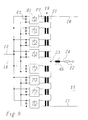
- FIG. 9 is a preferred embodiment for one Inverter reproduced according to the invention.
- the inverter of FIG. 9 is essentially the same in construction the inverter of Fig. 2.
- the tertiary windings on the transformer 19 and the associated filter circuit 25 are omitted here for the sake of simplicity.
- a resistor 22 leads to earth, is for damping or suppression of common mode currents in the earth connection one Saturation choke 49 provided in series with resistor 22.
- the characteristic of the saturation choke 49 is included dimensioned so that in normal (stationary) operation of the inverter 15, the expected in-phase Currents at the small number of 8 inverter bridges B1, .., B8 can be relatively high, strongly damped are, while in the event of a short circuit, the saturation choke 49 is controlled in the saturation and the short circuit current largely unhindered. This is the voltage-time area the saturation choke of the expected Voltage-time area of the interference voltages adjusted in normal operation.
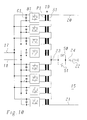
- the saturation choke 49 as a switching means, for example from two anti-parallel connected thyristors 50, 51 formed thyristor switch can be used, the Normally open and controlled in the event of a short circuit becomes.
- Example: With a transmitted nominal power of approx. 55MVA and a number of 8 inverter bridges without damping measures, there is a common mode current distortion (common mode currents), which accounts for approximately 3% of the nominal current (of approx. 400A). At a ground resistance 22 or 37 of R E 240 ⁇ , a maximum power loss of 100kW then drops. By inserting a saturation choke 49 with an unsaturated inductance of ⁇ 2H in the ground connection 24, the current distortion and thus the power loss dropping at the ground resistance can be reduced to ⁇ 5 kW.
- common mode current distortion common mode currents
- the invention is in Fig. 9, 10 in connection with a 1-phase Transformer has been explained. It goes without saying however, by itself that they are based on a 3-phase Transformer is applicable.
Abstract
Description
Die vorliegende Erfindung bezieht sich auf das Gebiet der Leistungselektronik. Sie betrifft einen Wechselrichter, umfassend eine Mehrzahl von am gleichen Gleichspannungszwischenkreis parallel arbeitenden Wechselrichterbrücken, deren Ausgangsspannungen über Summationsmittel aufsummiert werden, wobei die Wechselrichterbrücken jeweils nach Massgabe eines Trägersignals pulsdauermoduliert angesteuert werden und die Trägersignale der einzelnen Wechselrichterbrücken untereinander eine konstante Phasendifferenz aufweisen, und wobei die Summationsmittel einen Mittelabgriff aufweisen, welcher über eine Erdverbindung geerdet ist.The present invention relates to the field of Power electronics. It relates to an inverter, comprehensively a plurality of on the same DC link parallel working inverter bridges, their Output voltages are summed up by summation means, where the inverter bridges according to a Carrier signal can be controlled and the pulse duration modulated Carrier signals between the individual inverter bridges have a constant phase difference, and wherein the Summation means have a center tap, which over an earth connection is earthed.
Zur Verbindung von Stromnetzen mit unterschiedlicher Phasenzahl
und/oder Wechselspannungsfrequenz, wie z.B. zwischen einem
50Hz-Drehstromnetz und einem einphasigen 16 2/3Hz-Bahnnetz,
werden zunehmend mit Leistungshalbleitern ausgerüstete
vollstatische Kupplungen bzw. Bahnstromumrichter eingesetzt,
die häufig als Umrichter mit Gleichspannungszwischenkreis
ausgebildet sind. Gemäss Fig. 1 umfasst ein solcher Bahnstromumrichter
10 beispielsweise einen (thyristorbestückten)
Stromrichter 13, der über einen Transformator 12 den Drehstrom
aus dem Drehstromnetz 11 abnimmt und in einen Gleichstrom
umwandelt, einen Gleichspannungszwischenkreis 14 zur
Glättung bzw. Zwischenspeicherung, und einen Wechselrichter
15, der den Gleichstrom wieder in einen Wechselstrom der gewünschten
Frequenz umwandelt und in das Bahnnetz 16 einspeist.For connecting power grids with different phases
and / or AC voltage frequency, e.g. between one
50Hz three-phase network and a single-
Im Wechselrichter 15 werden üblicherweise eine oder mehrere
parallel arbeitende Wechselrichterbrücken mit schaltbaren
Ventilen (z.B. GTOs) eingesetzt, die pulsdauermoduliert angesteuert
werden und die gewünschte sinusförmige Ausgangsspannung
durch eine Abfolge von dauermodulierten Rechteckimpulsen
wechselnder Polarität approximieren. Zur Pulsdauermodulation
wird dabei üblicherweise eine dreieckförmige Hilfssteuerspannung
verwendet. Einzelheiten der Ansteuerung können beispielsweise
einem Sonderdruck (Nr. 9608-1000-0) der Anmelderin,
"Vollstatische 100-MW-Frequenzkupplung Bremen", entnommen
werden. Werden mehrere Wechselrichterbrücken parallel betrieben,
werden die Ausgangsspannungen aufsummiert. Eine Verringerung
des Oberschwingungsgehalts wird dabei dadurch erreicht,
dass die Ansteuerung der einzelnen Wechselrichterbrücken
über die Hifssteuerspannungen phasenverschoben erfolgt.Usually one or more are in the
Ein beispielhafter Aufbau eines Wechselrichters 15 ist in
Fig. 2 wiedergegeben. Der Wechselrichter 15 dieses Beispiels
umfasst 8 parallel arbeitende Wechselrichterbrücken B1,. ,B8,
die jeweils mit einem parallelen Kondensator C1,..,C8 am Eingang
an die vom Gleichspannungszwischenkreis 14 kommenden
Eingangsleitungen 17, 18 angeschlossen sind. Zur Summation
der Ausgangsspannungen der Wechselrichterbrücken B1,..,B8 ist
ein Transformator 19 vorgesehen, der für jede der Wechselrichterbrücken
B1,..,B8 ein Wicklungspaar aus einer Primärwicklung
P1,..,P8 und einer Sekundärwicklung S1,..,S8 enthält.
Die Ausgänge der Wechselrichterbrücken B1,..,B8 sind
jeweils an die entsprechenden Primärwicklungen P1,..,P8 angeschlossen,
die Sekundärwicklungen S1,..,S8 sind in Reihe geschaltet.
Das summierte Ausgangssignal steht an den Ausgangsleitungen
20, 21 zur Verfügung. Zur Unterdrückung von Oberschwingungen
kann der Transformator 19 zusätzlich mit Tertiärwicklungen
T1,..,T8 ausgestattet sein, die in Reihe geschaltet
und durch eine entsprechende Filterschaltung 25 bedämpft
sind (siehe dazu beispielsweise die EP-B1-0 149 169).
Beispielhafte dauermodulierte und phasenverschobene Impulsreihen
für die Wechselrichterbrücken B1,..,B8 sind in Fig. 3
wiedergegeben. Durch Summation der einzelnen Impulsfolgen im
Transformator 19 ergibt sich daraus die resultierende Summenspannung
uBi in Fig. 4.An exemplary construction of an
Probleme mit der in Fig. 2 dargestellten Art von Wechselrichter
ergeben sich nun, wenn - wie es bei manchen Bahnnetzen
erforderlich ist - der Transformator 19 des Wechselrichters
15 an einem Mittelabgriff 23 durch eine Erdverbindung 24 über
einen Widerstand 22 (oder auch ohne Widerstand, d.h. "hart")
geerdet wird (siehe Fig. 2). Diese Probleme lassen sich anhand
der in Fig. 5 bis 8 wiedergegebenen Ersatzschaltbilder
verdeutlichen: Der Wechselrichter, der als Spannungsquellenumrichter
(Voltage Source Converter, VSC) arbeitet, kann
grundsätzlich (Fig. 5) durch eine Spannungsquelle 26 mit der
Spannung uBi beschrieben werden, die einen entsprechenden
Strom iBi durch einen Kreis treibt, der durch die Impedanzen
27, 28 und 29 gebildet wird. Die Impedanzen 27 und 28 mit den
Werten z1 bzw. z2 repräsentieren den Transformator 19, die
Impedanz 29 mit dem Wert z3 repräsentiert die Filterschaltung
25. Das Bahnnetz 16 lässt sich im Ersatzschaltbild durch die
Impedanz 30 (z4) und die Spannungsquelle 31 beschreiben.Problems now arise with the type of inverter shown in FIG. 2 if - as is required in some rail networks - the
Durch die Erdung (über den Widerstand 22) am Mittelabgriff 23
des Transformators 19 kann das Ersatzschaltbild des VSC aus
Fig. 5 in ein Ersatzschaltbild gemäss Fig. 6 überführt werden.
Die Spannungsquelle 26 ist hier in zwei Spannungsquellen
32 und 33 mit den Teilspannungen uBi,a und uBi,b aufgeteilt,
wobei gilt:
Die Impedanzen 27 und 28 des Transformators 19 sind in Fig. 6
nun aufgeteilt in Impedanzen 34 und 39 bzw. 35 und 40 mit jeweils
der Hälfte des ursprünglichen Impedanzwertes, nämlich
z1/2 und z2/2. Die Impedanz 29 mit dem Wert z3 bleibt erhalten,
während die Impedanz 30 und die Spannungsquelle 31 des
Bahnnetzes 16 ebenfalls aufgeteilt werden in die Impedanzen
36 und 41 (jeweils mit dem Wert z4/2) bzw. Spannungsquellen
42 und 43. Die Erdung über den Mittelabgriff 23 des Transformators
19 wird in Fig. 6 durch den Widerstand 37 mit dem Wert
RE repräsentiert. Ein entsprechender Widerstand 38 mit dem
Wert RE,r beschreibt den gesamten Fern-Erdungswiderstand des
Bahnnetzes 16.The
Nach dem Konzept der modalen Zerlegung ("Modal Decomposition")
kann das Ersatzschaltbild der Fig. 6 in zwei überlagerte
Teilsysteme zerlegt werden, nämlich in das Gleichtakt-System
("Common Mode System") und das Gegentakt-System
("Differential Mode System"). Die beiden überlagerten Systeme
können dann getrennt voneinander behandelt und die resultierenden
Ströme und Spannungen nach Beendigung der Analyse einfach
addiert werden, um die realen physikalischen Grössen zu
erhalten. Das Ersatzschaltbild im Gleichtakt-System für die
obere Hälfte des VSC ist in Fig. 7 wiedergegeben. Neben den
bereits bekannten Impedanzen 34, 35 und 36 befinden sich im
Stromkreis die Widerstände 45 und 46, welche jeweils das Doppelte
der Erdungswiderstände 37 bzw. 38 ausmachen. Die Spannungsquelle
44 gibt eine Spannung uBi,CM ab, die einen Strom
iBi,CM durch den Kreis treibt. Das Ersatzschaltbild im Gegentakt-System
für die obere Hälfte des VSC ist in Fig. 8 dargestellt.
Neben den bereits bekannten Impedanzen 34, 35 und 36
ist hier zusätzlich die Impedanz 48 vorhanden, welche der
halben Impedanz 29 entspricht und für die Filterschaltung 25
charakteristisch ist. Die Spannungsquelle 47 gibt eine Spannung
uBi,D ab, die einen Strom iBi,D durch den Kreis treibt.According to the concept of modal decomposition, the equivalent circuit diagram of FIG. 6 can be broken down into two superimposed subsystems, namely the common mode system and the push-pull system (differential mode system). ). The two superimposed systems can then be treated separately from one another and the resulting currents and voltages can simply be added after the end of the analysis to obtain the real physical quantities. The equivalent circuit diagram in the common mode system for the upper half of the VSC is shown in FIG. 7. In addition to the already known
Für die Spannungen und Ströme ergibt sich der folgende Zusammenhang:
Aus den Fig. 5 bis 8 und den Gleichungen (1) bis (5) ergibt sich unmittelbar, dass die Gleichtaktspannung uBi,CM unerwünscht ist, weil sie einen Gleichtaktstrom iBi,CM treibt, der nur durch die Erdungswiderstände 37 und 38 zurückfliessen kann. Die Höhe des Gleichtaktstromes iBi,CM ist hauptsächlich durch die Impedanzen z1 und z2 des Transformators 19 begrenzt. Der Gleichtaktstrom iBi,CM hat zwei nachteilige Wirkungen:
- Er bewirkt erhebliche Verluste sowohl im
lokalen Erdungswiderstand 22 bzw. 37 als auch im Fern-Erdungswiderstand 38. Wie Simulationen einer realen Anlage (ca. 50MW) zeigen, können die Verluste im Erdungswiderstand 22 (bei einem nominalen Widerstandswert von RE = 334 Ω) ungefähr 50kW betragen und sind daher von einer unakzeptablen Grössenordnung. - Er kann in dem Bahnnetz (z.B. einem 138kV-Netz) Störungen in benachbarten Kommunikationseinrichtungen hervorrufen.
- It causes considerable losses both in the
local earth resistance remote earth resistance 38. As simulations of a real system (approx. 50 MW) show, the losses in the earth resistance 22 (with a nominal resistance value of R E = 334 Ω) are around 50kW and are therefore of an unacceptable order of magnitude. - In the rail network (eg a 138 kV network) it can cause interference in neighboring communication facilities.
Es ist daher Aufgabe der Erfindung, einen VSC-Wechselrichter zu schaffen, bei welchem die über die Erdverbindung fliessenden Ströme unterdrückt bzw. auf einen unschädlichen Wert gedämpft werden.It is therefore an object of the invention to provide a VSC inverter to create, in which the flowing over the earth connection Currents suppressed or to a harmless value be dampened.
Die Aufgabe wird bei einem Wechselrichter der eingangs genannten Art dadurch gelöst, dass zur Dämpfung bzw. Unterdrückung von über die Erdverbindung fliessenden gleichphasigen Störströmen und den damit verbundenen Störspannungen in der Erdverbindung Schaltmittel angeordnet sind. Durch die Anordnung der Schaltmittel direkt in der Erdverbindung kann verhindert werden, dass im Normalfall (wenn die Schaltmittel offen sind) gleichphasige Störströme über die Erdverbindung fliessen. Im Kurzschlussfall können die Schaltmittel geschlossen werden, so dass die Kurzschlussströme zur Erde abfliessen können. The task is performed with an inverter of the type mentioned Art solved in that for damping or suppression of in-phase flowing over the earth connection Interference currents and the associated interference voltages in the earth connection switching means are arranged. Through the Arrangement of the switching means directly in the earth connection can be prevented that normally (when the switching means open-phase interference currents via the earth connection flow. In the event of a short circuit, the switching means can be closed so that the short-circuit currents flow to earth can.
Eine erste bevorzugte Ausführungsform der Erfindung zeichnet sich dadurch aus, dass die Schaltmittel eine als Sättigungsdrossel ausgebildete Drossel umfassen. Die Drossel stellt für die Gleichtaktströme bei geeigneter Auslegung eine hohe Impedanz dar, ohne die ohmsche Verbindung des Mittelabgriffs zur Erde im Fehlerfall zu beeinträchtigen. Zugleich ist die Drossel als passives Bauelement einfach und sicher in der Funktion.A first preferred embodiment of the invention draws is characterized in that the switching means as a saturation choke trained throttle include. The throttle represents the common mode currents with a suitable design have a high impedance without the ohmic connection of the center tap to affect the earth in the event of a fault. At the same time it is Choke as a passive component simple and safe in the Function.
Im normalen Betriebsfall erfüllt eine einfache Drossel problemlos die an sie gestellten Anforderungen. Probleme würden sich jedoch im Falle eines Kurzschlusses im Bahnnetz ergeben, weil dann die hohe Impedanz der Drossel ein Abfliessen des steil ansteigenden Kurzschlusstromes zur Erde verhinderte und damit andere Anlagenteile gefährdete. Die Aufhebung der Dämpfungsfunktion im Kurzschlussfall wird dadurch erreicht, dass die Drossel als Sättigungsdrossel ausgebildet ist, deren Spannungs-Zeit-Fläche der zu erwartenden Spannungs-Zeit-Fläche der Störspannungen bzw. Störströme im Normalbetrieb angepasst ist. Im Normalfall arbeitet die Sättigungsdrossel unterhalb der Sättigung und dämpft die in der Erdverbindung fliessenden Ströme. Im Kurzschlussfall geht die Sättigungsdrossel in die Sättigung und lässt dann weitgehend ungehindert den Kurzschlusstrom passieren.In normal operation, a simple throttle fulfills easily the demands placed on them. Would be problems however, in the event of a short circuit in the rail network, because then the high impedance of the choke causes the prevented steep short-circuit current to earth and so that other parts of the system are endangered. The lifting of the Damping function in the event of a short circuit is achieved that the choke is designed as a saturation choke, the Voltage-time area of the expected voltage-time area the interference voltages or interference currents in normal operation is adjusted. The saturation choke normally works below saturation and dampens that in the earth connection flowing currents. In the event of a short circuit, the saturation choke goes into saturation and then leaves largely unimpeded pass the short-circuit current.
Eine andere bevorzugte Ausführungsform zeichnet sich dadurch aus, dass die Schaltmittel einen Thyristorschalter umfassen. Im normalen Betrieb ist der Thyristorschalter geschlossen und verhindert so sicher, dass die genannten Störströme über die Erdverbindung fliessen können. Im Kurzschlussfall wird der Thyristorschalter, der z.B aus zwei antiparallelen Thyristoren besteht, geschlossen, und die Kurzschlusströme können ungehindert über die Erdverbindung fliessen. Another preferred embodiment is characterized by this from that the switching means comprise a thyristor switch. In normal operation, the thyristor switch is closed and thus reliably prevents the interference currents mentioned via the Earth connection can flow. In the event of a short circuit, the Thyristor switch, e.g. made of two anti-parallel thyristors exists, closed, and the short-circuit currents can be unhindered flow over the earth connection.
Weitere Ausführungsformen ergeben sich aus den abhängigen Ansprüchen.Further embodiments result from the dependent claims.
Bevorzugt wird ein Wechselrichters nach der Erfindung in einem Umrichter mit Gleichspannungszwischenkreis, insbesondere in einem Bahnstromumrichter oder einer Frequenz kupplung, eingesetzt.An inverter according to the invention is preferred in one DC-link converter, in particular in a traction current converter or a frequency coupling.
Die Erfindung soll nachfolgend anhand von Ausführungsbeispielen im Zusammenhang mit der Zeichnung näher erläutert werden. Es zeigen
- Fig. 1
- den prinzipiellen Aufbau eines Bahnstromumrichters;
- Fig. 2
- das Blockschaltbild eines für den Bahnstromumrichter nach Fig. 1 geeigneten Wechselrichters mit einer Mehrzahl von parallelen Wechselrichterbrücken und mit Mittelpunktserdung des Transformators;
- Fig. 3
- beispielhafte pulsdauermodulierte Ausgangsimpulsfolgen der einzelnen Wechselrichterbrücken aus Fig. 2;
- Fig. 4
- die sich durch Aufsummierung der Ausgangsimpulsfolgen aus Fig. 3 ergebende Summenspannung;
- Fig. 5
- das Ersatzschaltbild des mit dem Bahnnetz verbundenen Wechselrichters aus Fig. 4 ohne Mittelpunktserdung des Transformators;
- Fig. 6
- das zu Fig. 5 entsprechende Ersatzschaltbild bei vorhandener Mittelpunktserdung;
- Fig. 7
- das aus dem Ersatzschaltbild der Fig. 6 abgeleitete Ersatzschaltbild für das Gleichtakt-Teilsystem;
- Fig. 8
- das aus dem Ersatzschaltbild der Fig. 6 abgeleitete Ersatzschaltbild für das Gegentakt-Teilsystem;
- Fig. 9
- ein erstes bevorzugtes Ausführungsbeispiel für einen Wechselrichter nach der Erfindung mit einer sättigbaren Drossel zur Unterdrückung der in der Erdleitung fliessenden Gleichtaktströme; und
- Fig. 10
- ein zweites bevorzugtes Ausführungsbeispiel für einen Wechselrichter nach der Erfindung mit einem Thyristorschalter zur Unterdrückung der in der Erdleitung fliessenden Gleichtaktströme.
- Fig. 1
- the basic structure of a traction current converter;
- Fig. 2
- the block diagram of a suitable for the traction current converter of Figure 1 inverter with a plurality of parallel inverter bridges and with center grounding of the transformer.
- Fig. 3
- exemplary pulse duration modulated output pulse sequences of the individual inverter bridges from FIG. 2;
- Fig. 4
- the sum voltage resulting from the summation of the output pulse sequences from FIG. 3;
- Fig. 5
- the equivalent circuit diagram of the inverter connected to the rail network of Figure 4 without grounding the center of the transformer.
- Fig. 6
- the equivalent circuit diagram corresponding to FIG. 5 with existing center earthing;
- Fig. 7
- the equivalent circuit diagram derived from the equivalent circuit diagram in FIG. 6 for the common mode subsystem;
- Fig. 8
- the equivalent circuit diagram derived from the equivalent circuit diagram in FIG. 6 for the push-pull subsystem;
- Fig. 9
- a first preferred embodiment of an inverter according to the invention with a saturable choke to suppress the common mode currents flowing in the ground line; and
- Fig. 10
- a second preferred embodiment of an inverter according to the invention with a thyristor switch to suppress the common-mode currents flowing in the ground line.
In der Fig. 9 ist ein bevorzugtes Ausführungsbeispiel für einen
Wechselrichter nach der Erfindung wiedergegeben. Der
Wechselrichter der Fig. 9 gleicht in seinem Aufbau im wesentlichen
dem Wechselrichter der Fig. 2. Die Tertiärwicklungen
am Transformator 19 sowie die dazugehörige Filterschaltung 25
sind hier der Einfachheit halber weggelassen. In die Erdverbindung
24, die vom Mittelabgriff 23 des Transformators über
einen Widerstand 22 zur Erde führt, ist zur Dämpfung bzw. Unterdrückung
der Gleichtaktströme in der Erdverbindung eine
zum Widerstand 22 in Serie liegende Sättigungsdrossel 49 vorgesehen.
Die Charakteristik der Sättigungsdrossel 49 ist dabei
so bemessen, dass im normalen (stationären) Betriebsfall
des Wechselrichters 15 die zu erwartenden gleichphasigen
Ströme, die bei der geringen Anzahl von 8 Wechselrichterbrücken
B1,..,B8 relativ hoch sein können, stark gedämpft
werden, während im Kurzschlussfall die Sättigungsdrossel 49
in die Sättigung gesteuert wird und den Kurzschlusstrom
weitgehend ungehindert passieren lässt. Dazu wird die Spannungs-Zeit-Fläche
der Sättigungsdrossel der zu erwartenden
Spannungs-Zeit-Fläche der Störspannungen im Normalbetrieb angepasst.9 is a preferred embodiment for one
Inverter reproduced according to the invention. Of the
The inverter of FIG. 9 is essentially the same in construction
the inverter of Fig. 2. The tertiary windings
on the
Wie bereits weiter oben erwähnt kann gemäss Fig. 10 anstelle
der Sättigungsdrossel 49 als Schaltmittel auch ein beispielsweise
aus zwei antiparallel geschalteten Thyristoren
50, 51 gebildeter Thyristorschalter verwendet werden, der im
Normalfall offen ist und im Kurzschlussfall durchgesteuert
wird.As already mentioned above, instead of FIG. 10
the
Weiterhin ist es denkbar, die Sättigungsdrossel 49 auch bei
einem Wechselrichter einzusetzen, der am Mittelabgriff des
Transformators "hart" geerdet ist, d.h., keinen speziellen
Erdungswiderstand 22 aufweist.It is also conceivable to also apply the
Beispiel: Es ergibt sich bei einer übertragenen Nennleistung
von ca. 55MVA und einer Anzahl von 8 Wechselrichterbrücken
ohne Dämpfungsmassnahmen eine Gleichtakt-Stromverzerrung
(Gleichtaktströme), die etwa 3% des Nennstromes (von ca.
400A) ausmacht. An einem Erdungswiderstand 22 bzw. 37 von RE
= 240Ω fällt dann eine maximale Verlustleistung von 100kW
ab. Durch Einfügung einer Sättigungsdrossel 49 mit einer ungesättigten
Induktivität von ≥ 2H in die Erdverbindung 24
kann die Stromverzerrung und damit die am Erdungswiderstand
abfallende Verlustleistung auf < 5kW reduziert werden. Example: With a transmitted nominal power of approx. 55MVA and a number of 8 inverter bridges without damping measures, there is a common mode current distortion (common mode currents), which accounts for approximately 3% of the nominal current (of approx. 400A). At a
Die Erfindung ist in Fig. 9, 10 im Zusammenhang mit einem 1-phasigen Transformator erläutert worden. Es versteht sich jedoch von selbst, dass sie entsprechend auf einen 3-phasigen Transformator anwendbar ist.The invention is in Fig. 9, 10 in connection with a 1-phase Transformer has been explained. It goes without saying however, by itself that they are based on a 3-phase Transformer is applicable.
- 1010th
- BahnstromumrichterTraction current converter
- 1111
- DrehstromnetzThree-phase network
- 1212th
- Transformator (3-phasig)Transformer (3-phase)
- 1313
- StromrichterPower converter
- 1414
- GleichspannungszwischenkreisDC link
- 1515
- WechselrichterInverter
- 1616
- BahnnetzRailway network
- 17,1817.18
- Eingangsleitung (Wechselrichter)Input line (inverter)
- 1919th
- Transformator (Wechselrichter)Transformer
- 20,2120.21
- Ausgangsleitung (Wechselrichter)Output line (inverter)
- 2222
- Widerstandresistance
- 2323
- Mittelabgriff (Transformator)Center tap (transformer)
- 2424th
- ErdverbindungEarth connection
- 2525th
- FilterschaltungFilter circuit
- 26,3126.31
- SpannungsquelleVoltage source
- 27,..,3027, .., 30
- ImpedanzImpedance
- 32, 3332, 33
- SpannungsquelleVoltage source
- 34,..,3634, .., 36
- ImpedanzImpedance
- 37,3837.38
- Widerstandresistance
- 39,..,4139, .., 41
- ImpedanzImpedance
- 42,4342.43
- SpannungsquellenVoltage sources
- 44,4744.47
- SpannungsquelleVoltage source
- 45,4645.46
- Widerstand resistance
- 4848
- ImpedanzImpedance
- 4949
- Drossel (Sättigungsdrossel)Choke (saturation choke)
- 50,5150.51
- ThyristorThyristor
- B1,..,B8B1, .., B8
- WechselrichterbrückeInverter bridge
- C1,..,C8C1, .., C8
- Kondensatorcapacitor
- P1,..,P8P1, .., P8
- PrimärwicklungPrimary winding
- S1,..,S8S1, .., S8
- SekundärwicklungSecondary winding
- T1,..,T8T1, .., T8
- TertiärwicklungTertiary winding
Claims (8)
Applications Claiming Priority (2)
| Application Number | Priority Date | Filing Date | Title |
|---|---|---|---|
| DE19736612 | 1997-08-22 | ||
| DE19736612A DE19736612A1 (en) | 1997-08-22 | 1997-08-22 | Inverter |
Publications (3)
| Publication Number | Publication Date |
|---|---|
| EP0903843A2 true EP0903843A2 (en) | 1999-03-24 |
| EP0903843A3 EP0903843A3 (en) | 1999-06-02 |
| EP0903843B1 EP0903843B1 (en) | 2002-09-18 |
Family
ID=7839875
Family Applications (1)
| Application Number | Title | Priority Date | Filing Date |
|---|---|---|---|
| EP98810735A Expired - Lifetime EP0903843B1 (en) | 1997-08-22 | 1998-07-30 | Inverter |
Country Status (8)
| Country | Link |
|---|---|
| US (1) | US6169676B1 (en) |
| EP (1) | EP0903843B1 (en) |
| JP (1) | JPH11136956A (en) |
| KR (1) | KR19990023779A (en) |
| AT (1) | ATE224609T1 (en) |
| DE (2) | DE19736612A1 (en) |
| NO (1) | NO983808L (en) |
| ZA (1) | ZA987063B (en) |
Cited By (1)
| Publication number | Priority date | Publication date | Assignee | Title |
|---|---|---|---|---|
| DE102018109107B3 (en) | 2018-04-17 | 2019-05-23 | Sma Solar Technology Ag | A monitoring device and method for monitoring a solar generator for earth faults |
Families Citing this family (18)
| Publication number | Priority date | Publication date | Assignee | Title |
|---|---|---|---|---|
| JP4112930B2 (en) * | 2002-09-04 | 2008-07-02 | 東芝三菱電機産業システム株式会社 | Inverter device |
| US7050311B2 (en) * | 2003-11-25 | 2006-05-23 | Electric Power Research Institute, Inc. | Multilevel converter based intelligent universal transformer |
| US20070223258A1 (en) * | 2003-11-25 | 2007-09-27 | Jih-Sheng Lai | Multilevel converters for intelligent high-voltage transformers |
| US6954366B2 (en) * | 2003-11-25 | 2005-10-11 | Electric Power Research Institute | Multifunction hybrid intelligent universal transformer |
| US20070230226A1 (en) * | 2003-11-25 | 2007-10-04 | Jih-Sheng Lai | Multilevel intelligent universal auto-transformer |
| TWI299616B (en) * | 2005-12-16 | 2008-08-01 | Via Tech Inc | Transmitter and transmission circuit |
| US20090080225A1 (en) * | 2005-12-28 | 2009-03-26 | Abb Research Ltd | Voltage source converter and method of controlling a voltage source converter |
| US7558092B2 (en) * | 2006-02-28 | 2009-07-07 | Tdk Corporation | Switching power supply unit |
| JP5643104B2 (en) * | 2007-11-30 | 2014-12-17 | アレンコン・アクイジション・カンパニー・エルエルシー | Multiphase grid synchronous adjustment current source inverter system |
| US9350166B2 (en) | 2010-10-05 | 2016-05-24 | Alencon Acquisition Co., Llc | High voltage energy harvesting and conversion renewable energy utility size electric power systems and visual monitoring and control systems for said systems |
| US8885371B2 (en) * | 2010-10-19 | 2014-11-11 | Astec International Limited | Multi-level parallel power converters |
| AU2012253314B2 (en) | 2011-05-12 | 2016-11-24 | Alencon Acquisition Co., Llc | High voltage energy harvesting and conversion renewable energy utility size electric power systems and visual monitoring and control systems |
| KR101491658B1 (en) * | 2013-04-25 | 2015-02-09 | 주식회사 피에스텍 | Switching Amplifier Apparatus and Control Method Thereof |
| JP6148164B2 (en) * | 2013-12-02 | 2017-06-14 | 東芝三菱電機産業システム株式会社 | Uninterruptible power supply system |
| JP6014061B2 (en) * | 2014-01-22 | 2016-10-25 | 東芝三菱電機産業システム株式会社 | Uninterruptible power supply system |
| JP6331480B2 (en) * | 2014-03-03 | 2018-05-30 | 株式会社リコー | Inverter device and plasma generator |
| US10483759B2 (en) | 2016-04-07 | 2019-11-19 | Alencon Acquisition Co., Llc | Integrated multi-mode large-scale electric power support system for an electrical grid |
| WO2018233822A1 (en) * | 2017-06-21 | 2018-12-27 | Abb Schweiz Ag | Model based current control of a three-to-single-phase power converter |
Citations (1)
| Publication number | Priority date | Publication date | Assignee | Title |
|---|---|---|---|---|
| EP0581322A2 (en) * | 1992-07-31 | 1994-02-02 | Asea Brown Boveri Ag | Method of damping harmonics and device for connecting to a network |
Family Cites Families (10)
| Publication number | Priority date | Publication date | Assignee | Title |
|---|---|---|---|---|
| US3671810A (en) | 1969-09-18 | 1972-06-20 | Singer Co | Saturated core transient current limiter |
| CH633918A5 (en) | 1978-04-10 | 1982-12-31 | Bbc Brown Boveri & Cie | Method for rapidly reducing the short-circuit current in a network, and a device for carrying out the method |
| DE3010099A1 (en) | 1980-02-25 | 1981-09-03 | BBC AG Brown, Boveri & Cie., Baden, Aargau | ELECTRONIC PROTECTIVE CIRCUIT |
| CA1203007A (en) * | 1983-07-06 | 1986-04-08 | Dale B. Williston | Ground voltage suppression |
| DE3602496A1 (en) | 1986-01-28 | 1987-07-30 | Klein Kg Elektro Geraete G | Method for the parallel operation of invertors, and an invertor arrangement for carrying out the method |
| US5065303A (en) | 1990-07-24 | 1991-11-12 | Sundstrand Corporation | Transformer-coupled and phase-shifted inverter |
| DE4142644C1 (en) | 1991-12-21 | 1993-02-04 | Fraunhofer-Gesellschaft Zur Foerderung Der Angewandten Forschung Ev, 8000 Muenchen, De | |
| US5508905A (en) | 1992-08-06 | 1996-04-16 | Metropolitan Pump Company | Low distortion variable output power supply |
| DE19736614A1 (en) * | 1997-08-22 | 1999-02-25 | Asea Brown Boveri | Inverter |
| DE19736613A1 (en) * | 1997-08-22 | 1999-02-25 | Asea Brown Boveri | Inverter |
-
1997
- 1997-08-22 DE DE19736612A patent/DE19736612A1/en not_active Withdrawn
-
1998
- 1998-07-30 AT AT98810735T patent/ATE224609T1/en not_active IP Right Cessation
- 1998-07-30 DE DE59805592T patent/DE59805592D1/en not_active Expired - Fee Related
- 1998-07-30 EP EP98810735A patent/EP0903843B1/en not_active Expired - Lifetime
- 1998-08-06 ZA ZA987063A patent/ZA987063B/en unknown
- 1998-08-19 NO NO983808A patent/NO983808L/en not_active Application Discontinuation
- 1998-08-20 JP JP10233393A patent/JPH11136956A/en active Pending
- 1998-08-21 US US09/137,539 patent/US6169676B1/en not_active Expired - Fee Related
- 1998-08-21 KR KR1019980033977A patent/KR19990023779A/en not_active Application Discontinuation
Patent Citations (1)
| Publication number | Priority date | Publication date | Assignee | Title |
|---|---|---|---|---|
| EP0581322A2 (en) * | 1992-07-31 | 1994-02-02 | Asea Brown Boveri Ag | Method of damping harmonics and device for connecting to a network |
Non-Patent Citations (1)
| Title |
|---|
| FIEBER ET AL: "STATISCHER UMRICHTER MULDENSTEIN" ELEKTRISCHE BAHNEN, Bd. 93, Nr. 12, Januar 1995, Seiten 43-48, XP000492379 m}nchen * |
Cited By (1)
| Publication number | Priority date | Publication date | Assignee | Title |
|---|---|---|---|---|
| DE102018109107B3 (en) | 2018-04-17 | 2019-05-23 | Sma Solar Technology Ag | A monitoring device and method for monitoring a solar generator for earth faults |
Also Published As
| Publication number | Publication date |
|---|---|
| KR19990023779A (en) | 1999-03-25 |
| NO983808D0 (en) | 1998-08-19 |
| JPH11136956A (en) | 1999-05-21 |
| ATE224609T1 (en) | 2002-10-15 |
| DE59805592D1 (en) | 2002-10-24 |
| NO983808L (en) | 1999-02-23 |
| DE19736612A1 (en) | 1999-02-25 |
| EP0903843A3 (en) | 1999-06-02 |
| US6169676B1 (en) | 2001-01-02 |
| ZA987063B (en) | 1999-02-08 |
| EP0903843B1 (en) | 2002-09-18 |
Similar Documents
| Publication | Publication Date | Title |
|---|---|---|
| EP0903843B1 (en) | Inverter | |
| DE2950247C2 (en) | Power supply system | |
| DE102007059289B4 (en) | Device for testing transformers | |
| DE102005012371A1 (en) | Twelve-pulse high-voltage direct-current meeting | |
| EP0166954B1 (en) | Method for the reduction of dynamic overvoltages in an alternating current grid system | |
| EP1040555A1 (en) | Converter connection assembly with a direct voltage intermediate circuit | |
| EP0212172B1 (en) | Current oscillations compensation method and device | |
| EP0898359A2 (en) | Inverter | |
| EP0682402B1 (en) | Output magnitudes rise limiting device for self-commutated constant voltage intermediate circuit converter | |
| EP1069673B1 (en) | Line filter | |
| EP0898358A2 (en) | Inverter | |
| CH642493A5 (en) | TRANSMISSION SYSTEM FOR HIGH VOLTAGE DC. | |
| EP3622621A1 (en) | Multilevel power converter | |
| WO1999049559A2 (en) | Method and device for suppressing interference in frequency converters | |
| WO2018113926A1 (en) | Power converter | |
| EP3180844B1 (en) | Power converter arrangement with short-circuit unit and method for separating an ac voltage line | |
| EP3741023B1 (en) | Device and method for controlling a load flow in an alternating-voltage network | |
| DE4235223C1 (en) | Operating and braking circuit for several AC motors coupled via load - has single brake switch connecting braking resistance bridged by free-running diode across DC voltage rail pair supplying all motors | |
| DE102018208626A1 (en) | Magnetically adjustable reactor for reactive power compensation with capacitively connected auxiliary windings | |
| DE1463574B1 (en) | Earth fault protection device for alternating or three-phase systems that are galvanically separated from the mains | |
| EP3827510B1 (en) | Frequency inverter with simplified precharging circuit | |
| DE102004002261A1 (en) | Kommutierungsfilter | |
| WO1991003861A1 (en) | Circuit for a controlled power converter | |
| DE3938700C2 (en) | ||
| EP1363387A2 (en) | Circuit arrangement for a DC link |
Legal Events
| Date | Code | Title | Description |
|---|---|---|---|
| PUAI | Public reference made under article 153(3) epc to a published international application that has entered the european phase |
Free format text: ORIGINAL CODE: 0009012 |
|
| AK | Designated contracting states |
Kind code of ref document: A2 Designated state(s): AT CH DE LI SE |
|
| AX | Request for extension of the european patent |
Free format text: AL;LT;LV;MK;RO;SI |
|
| PUAL | Search report despatched |
Free format text: ORIGINAL CODE: 0009013 |
|
| AK | Designated contracting states |
Kind code of ref document: A3 Designated state(s): AT BE CH CY DE DK ES FI FR GB GR IE IT LI LU MC NL PT SE |
|
| AX | Request for extension of the european patent |
Free format text: AL;LT;LV;MK;RO;SI |
|
| 17P | Request for examination filed |
Effective date: 19991108 |
|
| AKX | Designation fees paid |
Free format text: AT CH DE LI SE |
|
| 17Q | First examination report despatched |
Effective date: 20000314 |
|
| RAP1 | Party data changed (applicant data changed or rights of an application transferred) |
Owner name: ABB INDUSTRIE AG |
|
| GRAG | Despatch of communication of intention to grant |
Free format text: ORIGINAL CODE: EPIDOS AGRA |
|
| GRAG | Despatch of communication of intention to grant |
Free format text: ORIGINAL CODE: EPIDOS AGRA |
|
| GRAH | Despatch of communication of intention to grant a patent |
Free format text: ORIGINAL CODE: EPIDOS IGRA |
|
| RAP1 | Party data changed (applicant data changed or rights of an application transferred) |
Owner name: ABB SCHWEIZ AG |
|
| GRAH | Despatch of communication of intention to grant a patent |
Free format text: ORIGINAL CODE: EPIDOS IGRA |
|
| GRAA | (expected) grant |
Free format text: ORIGINAL CODE: 0009210 |
|
| AK | Designated contracting states |
Kind code of ref document: B1 Designated state(s): AT CH DE LI SE |
|
| REF | Corresponds to: |
Ref document number: 224609 Country of ref document: AT Date of ref document: 20021015 Kind code of ref document: T |
|
| REG | Reference to a national code |
Ref country code: CH Ref legal event code: EP |
|
| REF | Corresponds to: |
Ref document number: 59805592 Country of ref document: DE Date of ref document: 20021024 |
|
| REG | Reference to a national code |
Ref country code: CH Ref legal event code: NV Representative=s name: ABB BUSINESS SERVICES LTD INTELLECTUAL PROPERTY (S |
|
| PLBE | No opposition filed within time limit |
Free format text: ORIGINAL CODE: 0009261 |
|
| STAA | Information on the status of an ep patent application or granted ep patent |
Free format text: STATUS: NO OPPOSITION FILED WITHIN TIME LIMIT |
|
| PG25 | Lapsed in a contracting state [announced via postgrant information from national office to epo] |
Ref country code: AT Free format text: LAPSE BECAUSE OF NON-PAYMENT OF DUE FEES Effective date: 20030730 |
|
| PG25 | Lapsed in a contracting state [announced via postgrant information from national office to epo] |
Ref country code: SE Free format text: LAPSE BECAUSE OF NON-PAYMENT OF DUE FEES Effective date: 20030731 Ref country code: LI Free format text: LAPSE BECAUSE OF NON-PAYMENT OF DUE FEES Effective date: 20030731 Ref country code: CH Free format text: LAPSE BECAUSE OF NON-PAYMENT OF DUE FEES Effective date: 20030731 |
|
| 26N | No opposition filed |
Effective date: 20030619 |
|
| PG25 | Lapsed in a contracting state [announced via postgrant information from national office to epo] |
Ref country code: DE Free format text: LAPSE BECAUSE OF NON-PAYMENT OF DUE FEES Effective date: 20040203 |
|
| EUG | Se: european patent has lapsed | ||
| REG | Reference to a national code |
Ref country code: CH Ref legal event code: PL |