EP0903826A1 - Feuerlöschvorrichtung insbesondere für Mittelspannungsschalttafeln - Google Patents
Feuerlöschvorrichtung insbesondere für Mittelspannungsschalttafeln Download PDFInfo
- Publication number
- EP0903826A1 EP0903826A1 EP98202429A EP98202429A EP0903826A1 EP 0903826 A1 EP0903826 A1 EP 0903826A1 EP 98202429 A EP98202429 A EP 98202429A EP 98202429 A EP98202429 A EP 98202429A EP 0903826 A1 EP0903826 A1 EP 0903826A1
- Authority
- EP
- European Patent Office
- Prior art keywords
- fact
- mass
- previous
- fumes
- flame
- Prior art date
- Legal status (The legal status is an assumption and is not a legal conclusion. Google has not performed a legal analysis and makes no representation as to the accuracy of the status listed.)
- Granted
Links
Images
Classifications
-
- H—ELECTRICITY
- H02—GENERATION; CONVERSION OR DISTRIBUTION OF ELECTRIC POWER
- H02B—BOARDS, SUBSTATIONS OR SWITCHING ARRANGEMENTS FOR THE SUPPLY OR DISTRIBUTION OF ELECTRIC POWER
- H02B13/00—Arrangement of switchgear in which switches are enclosed in, or structurally associated with, a casing, e.g. cubicle
- H02B13/02—Arrangement of switchgear in which switches are enclosed in, or structurally associated with, a casing, e.g. cubicle with metal casing
- H02B13/025—Safety arrangements, e.g. in case of excessive pressure or fire due to electrical defect
Definitions
- the present invention relates to a device for extinguishing the flame particularly in medium voltage electrical switchboards.
- medium and high voltage electrical switchboards normally comprise devices that have the function of conveying the flames that might be emitted following the occurrence of an arc inside the medium and high voltage switchboards to the outside.
- the aim of the present invention is to solve the problem explained above by providing a device for extinguishing the flame, particularly in medium voltage electrical switchboards, that makes it possible to prevent the propagation of the flame outside the zone occupied by the electrical switchboard, thus forming an assembly that undoubtedly respects the most rigorous standards in force.
- a particular object of the present invention is to provide a device in which the extinction of the flame is obtained in extremely short times, consequently preventing its propagation towards the outside.
- Another object of the present invention is to provide a device that makes simple and fast installation possible even in existing electrical switchboards without requiring special or complex modifications to be performed.
- Another object of the present invention is to provide a device that is able, as a result of its distinctive constructional characteristics, both to give greater guarantees of reliability and safety in use and, moreover, to be competitive from a purely economic standpoint.
- a device for extinguishing the flame particularly in medium voltage electrical switchboards characterised by the fact that it comprises, in the path for releasing the fumes produced by the occurrence of an arc inside the electrical switchboard, a body that is permeable to the passage of the fumes and has a mass that is capable of absorbing heat to extinguish the flame by cooling.
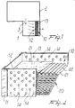
- the device for extinguishing the flame particularly in medium voltage electrical switchboards comprises a compartment 1 that can be connected to the cabinet 2 of a medium voltage switchboard and is in communication with the inside of the switchboard by means of a through hole 3.
- the compartment 1 is open towards the outside by means of a hole that is closed by a body, indicated by reference number 10, which is permeable to the passage of the fumes that might possibly be emitted inside the electrical switchboard and propagate towards the outside through the compartment 1.
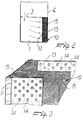
- the distinctive feature of the invention is constituted by the fact that the body 10 comprises a framework 11 that supports a first perforated plate 12 and a second perforated plate 13 that are spaced apart from one another and have a plurality of through holes 14 that are uniformly distributed.
- a mass with very low thermal inertia is provided inside the zone delimited between the plates 12 and 13, which has the main function of instantly absorbing the heat of the fumes in transit, obtaining a sharp drop in temperature that causes the flame to be extinguished by cooling.
- the distinctive feature of the invention is therefore to obtain flame extinction by exploiting a mass, preferably metal, that, by instantly absorbing the heat of the fumes, reduces the temperature and prevents the propagation of the flame.
- the low thermal inertia mass is made of stainless steel shavings packed in the zone between the plates 12 and 13.
- the low thermal inertia mass is formed by a pack of wire nets 15 with a fine mesh that preferably has a pitch of an average of approximately 0.2 mm or less.
- Metal materials such as stainless steel are preferably used, but it is conceptually possible to use other materials, which obviously have a low thermal inertia and are therefore able to instantly absorb the heat of the fumes.
- the device for extinguishing the flame makes it possible to provide a guarantee against the propagation of the flame by exploiting a new constructional criteria that is extremely valid from a practical standpoint and easy to make.
Landscapes
- Engineering & Computer Science (AREA)
- Power Engineering (AREA)
- Arc-Extinguishing Devices That Are Switches (AREA)
- Casings For Electric Apparatus (AREA)
- Distribution Board (AREA)
- Emergency Protection Circuit Devices (AREA)
- Special Wing (AREA)
Applications Claiming Priority (2)
| Application Number | Priority Date | Filing Date | Title |
|---|---|---|---|
| ITMI971736 | 1997-07-22 | ||
| IT97MI001736A IT1293755B1 (it) | 1997-07-22 | 1997-07-22 | Dispositivo per lo spegnimento della fiamma particolarmente in quadri elettrici a media tensione |
Publications (2)
| Publication Number | Publication Date |
|---|---|
| EP0903826A1 true EP0903826A1 (de) | 1999-03-24 |
| EP0903826B1 EP0903826B1 (de) | 2002-04-24 |
Family
ID=11377605
Family Applications (1)
| Application Number | Title | Priority Date | Filing Date |
|---|---|---|---|
| EP98202429A Expired - Lifetime EP0903826B1 (de) | 1997-07-22 | 1998-07-20 | Feuerlöschvorrichtung insbesondere für Mittelspannungsschalttafeln |
Country Status (5)
| Country | Link |
|---|---|
| EP (1) | EP0903826B1 (de) |
| AT (1) | ATE216807T1 (de) |
| DE (1) | DE69805032T2 (de) |
| ES (1) | ES2176900T3 (de) |
| IT (1) | IT1293755B1 (de) |
Cited By (5)
| Publication number | Priority date | Publication date | Assignee | Title |
|---|---|---|---|---|
| EP1557919A1 (de) * | 2004-01-21 | 2005-07-27 | Ormazabal Anlagentechnik GmbH | Elektrische gasisollierte Schaltanlage |
| CN1312711C (zh) * | 2004-02-20 | 2007-04-25 | 浙江正泰电器股份有限公司 | 带有气体消电离装置的灭弧室 |
| DE102008024069A1 (de) * | 2008-05-17 | 2009-11-26 | Areva Energietechnik Gmbh | Elektrische Schalteinheit insbesondere für den Mittelspannungsbereich |
| WO2019206617A1 (de) * | 2018-04-27 | 2019-10-31 | Siemens Aktiengesellschaft | Schaltschrank |
| EP3671993A1 (de) * | 2018-12-20 | 2020-06-24 | ABB Schweiz AG | Elektrisches lichtbogenabsorbersystem, schaltanlage mit einem elektrischen lichtbogenabsorbersystem und verfahren zum betreiben einer schaltanlage |
Families Citing this family (1)
| Publication number | Priority date | Publication date | Assignee | Title |
|---|---|---|---|---|
| CN115360595B (zh) * | 2022-08-22 | 2023-04-28 | 宇超电力股份有限公司 | 一种铠装中置金属封闭的开关柜及其使用方法 |
Citations (13)
| Publication number | Priority date | Publication date | Assignee | Title |
|---|---|---|---|---|
| FR561531A (fr) * | 1922-01-31 | 1923-10-23 | Thomson Houston Comp Francaise | Dispositif de protection pour appareils électriques disposés dans une enveloppe fermée |
| US3033961A (en) * | 1960-05-04 | 1962-05-08 | Ite Circuit Breaker Ltd | Serpentine corrugated arc product coolers |
| US3230331A (en) * | 1965-04-26 | 1966-01-18 | S & C Electric Co | Circuit interrupter construction with improved condenser |
| US3555224A (en) * | 1968-12-23 | 1971-01-12 | Gen Electric | Arc chute for an air circuit breaker |
| DE2817418A1 (de) * | 1978-04-18 | 1979-10-25 | Krone Gmbh | Schaltanlage mit definiertem ausstroemkanal fuer die gasabfuehrung bei stoerlichtbogenentstehung in einem feld |
| DE3424363A1 (de) * | 1984-07-03 | 1986-01-09 | Ritter Starkstromtechnik GmbH & Co, 4600 Dortmund | Stoerlichtbogenfeste elektrische anlagen |
| DE3525143A1 (de) * | 1985-07-13 | 1987-01-15 | Driescher Spezialfab Fritz | Transformatorstation |
| DE3541514A1 (de) * | 1985-11-21 | 1987-05-27 | Siemens Ag | Lichtbogenloeschkammer mit einem aufsatz zur weiteren abkuehlung austretender gase |
| EP0418755A2 (de) * | 1989-09-18 | 1991-03-27 | Mitsubishi Denki Kabushiki Kaisha | Strombegrenzender Stromkreisunterbrecher |
| DE4141685A1 (de) * | 1991-12-18 | 1993-06-24 | Sachsenwerk Ag | Schaltanlage fuer mittel- oder hochspannung |
| EP0666627A1 (de) * | 1994-02-03 | 1995-08-09 | Gec Alsthom T & D GmbH | Lichtbogenabsorber |
| DE19520698A1 (de) * | 1995-06-07 | 1996-12-12 | Ritter Starkstromtech | Elektrische Anlage, insbesondere Schaltanlage |
| EP0817223A1 (de) * | 1996-06-28 | 1998-01-07 | Schneider Electric Sa | Entionisierungsvorrichtung für Gase, insbesondere für Schaltgase in eine Lichtbogenlöschkammer eines Niederspannungslastschalters mit gegossenem Gehäuse, und mit einer solchen Vorrichtung versehene Lichtbogenlöschkammer |
-
1997
- 1997-07-22 IT IT97MI001736A patent/IT1293755B1/it active IP Right Grant
-
1998
- 1998-07-20 ES ES98202429T patent/ES2176900T3/es not_active Expired - Lifetime
- 1998-07-20 DE DE69805032T patent/DE69805032T2/de not_active Expired - Lifetime
- 1998-07-20 EP EP98202429A patent/EP0903826B1/de not_active Expired - Lifetime
- 1998-07-20 AT AT98202429T patent/ATE216807T1/de not_active IP Right Cessation
Patent Citations (13)
| Publication number | Priority date | Publication date | Assignee | Title |
|---|---|---|---|---|
| FR561531A (fr) * | 1922-01-31 | 1923-10-23 | Thomson Houston Comp Francaise | Dispositif de protection pour appareils électriques disposés dans une enveloppe fermée |
| US3033961A (en) * | 1960-05-04 | 1962-05-08 | Ite Circuit Breaker Ltd | Serpentine corrugated arc product coolers |
| US3230331A (en) * | 1965-04-26 | 1966-01-18 | S & C Electric Co | Circuit interrupter construction with improved condenser |
| US3555224A (en) * | 1968-12-23 | 1971-01-12 | Gen Electric | Arc chute for an air circuit breaker |
| DE2817418A1 (de) * | 1978-04-18 | 1979-10-25 | Krone Gmbh | Schaltanlage mit definiertem ausstroemkanal fuer die gasabfuehrung bei stoerlichtbogenentstehung in einem feld |
| DE3424363A1 (de) * | 1984-07-03 | 1986-01-09 | Ritter Starkstromtechnik GmbH & Co, 4600 Dortmund | Stoerlichtbogenfeste elektrische anlagen |
| DE3525143A1 (de) * | 1985-07-13 | 1987-01-15 | Driescher Spezialfab Fritz | Transformatorstation |
| DE3541514A1 (de) * | 1985-11-21 | 1987-05-27 | Siemens Ag | Lichtbogenloeschkammer mit einem aufsatz zur weiteren abkuehlung austretender gase |
| EP0418755A2 (de) * | 1989-09-18 | 1991-03-27 | Mitsubishi Denki Kabushiki Kaisha | Strombegrenzender Stromkreisunterbrecher |
| DE4141685A1 (de) * | 1991-12-18 | 1993-06-24 | Sachsenwerk Ag | Schaltanlage fuer mittel- oder hochspannung |
| EP0666627A1 (de) * | 1994-02-03 | 1995-08-09 | Gec Alsthom T & D GmbH | Lichtbogenabsorber |
| DE19520698A1 (de) * | 1995-06-07 | 1996-12-12 | Ritter Starkstromtech | Elektrische Anlage, insbesondere Schaltanlage |
| EP0817223A1 (de) * | 1996-06-28 | 1998-01-07 | Schneider Electric Sa | Entionisierungsvorrichtung für Gase, insbesondere für Schaltgase in eine Lichtbogenlöschkammer eines Niederspannungslastschalters mit gegossenem Gehäuse, und mit einer solchen Vorrichtung versehene Lichtbogenlöschkammer |
Cited By (6)
| Publication number | Priority date | Publication date | Assignee | Title |
|---|---|---|---|---|
| EP1557919A1 (de) * | 2004-01-21 | 2005-07-27 | Ormazabal Anlagentechnik GmbH | Elektrische gasisollierte Schaltanlage |
| CN1312711C (zh) * | 2004-02-20 | 2007-04-25 | 浙江正泰电器股份有限公司 | 带有气体消电离装置的灭弧室 |
| DE102008024069A1 (de) * | 2008-05-17 | 2009-11-26 | Areva Energietechnik Gmbh | Elektrische Schalteinheit insbesondere für den Mittelspannungsbereich |
| WO2019206617A1 (de) * | 2018-04-27 | 2019-10-31 | Siemens Aktiengesellschaft | Schaltschrank |
| US11451017B2 (en) | 2018-04-27 | 2022-09-20 | Siemens Energy Global GmbH & Co. KG | Switchgear cabinet |
| EP3671993A1 (de) * | 2018-12-20 | 2020-06-24 | ABB Schweiz AG | Elektrisches lichtbogenabsorbersystem, schaltanlage mit einem elektrischen lichtbogenabsorbersystem und verfahren zum betreiben einer schaltanlage |
Also Published As
| Publication number | Publication date |
|---|---|
| ATE216807T1 (de) | 2002-05-15 |
| DE69805032D1 (de) | 2002-05-29 |
| EP0903826B1 (de) | 2002-04-24 |
| IT1293755B1 (it) | 1999-03-10 |
| DE69805032T2 (de) | 2002-12-19 |
| ITMI971736A1 (it) | 1999-01-22 |
| ES2176900T3 (es) | 2002-12-01 |
Similar Documents
| Publication | Publication Date | Title |
|---|---|---|
| EP0903826A1 (de) | Feuerlöschvorrichtung insbesondere für Mittelspannungsschalttafeln | |
| US6548753B1 (en) | Flame suppression cabinet | |
| JP2021517708A (ja) | 火炎の外部漏出を防止可能な構造を有するessモジュール及びそれを含むバッテリーパック | |
| CN108010823B (zh) | 一种高响应速度的熔断器 | |
| JP2000106490A (ja) | 回路基板用キャビネット | |
| US6788518B1 (en) | Spark gap arrangement | |
| MY123817A (en) | Microwave leakage-preventing device for a microwave oven | |
| CN219323813U (zh) | 一种具有混合冷却剂的灭火装置 | |
| KR20090038964A (ko) | 소화에어로졸 발생기 | |
| HU213360B (en) | Protective power switch with arc extinguishing chamber | |
| US4569399A (en) | Safety enclosure | |
| KR20230130265A (ko) | 터미널 쇼트 방지를 위한 절연지를 구비한 기중 차단기 | |
| Lu et al. | Investigation on quenching characteristics of parallel narrow channels for deflagration flames | |
| KR200415012Y1 (ko) | 복합기능의 조립식 패널 | |
| JPH046898A (ja) | シェルフの耐火構造 | |
| JP2004344210A (ja) | 消火設備の局所用噴射ヘッド | |
| CN223615300U (zh) | 适用于电器柜的气溶胶灭火装置 | |
| CN214336590U (zh) | 一种断路器灭弧室 | |
| CN221947060U (zh) | 灭弧系统及断路器 | |
| CN216889627U (zh) | 一种防火耐烟电梯轿厢 | |
| CN213241969U (zh) | 一种消防系统用阻燃低烟无卤耐火电缆 | |
| CN220543779U (zh) | 断路器灭弧装置 | |
| CN215817066U (zh) | 一种防爆温控配电箱 | |
| CN220774274U (zh) | 一种隔弧板及断路器 | |
| PL174603B1 (pl) | Wyłącznik |
Legal Events
| Date | Code | Title | Description |
|---|---|---|---|
| PUAI | Public reference made under article 153(3) epc to a published international application that has entered the european phase |
Free format text: ORIGINAL CODE: 0009012 |
|
| AK | Designated contracting states |
Kind code of ref document: A1 Designated state(s): AT BE CH DE DK ES FI FR GB IT LI NL SE |
|
| AX | Request for extension of the european patent |
Free format text: AL;LT;LV;MK;RO;SI |
|
| 17P | Request for examination filed |
Effective date: 19990921 |
|
| AKX | Designation fees paid |
Free format text: AT BE CH DE DK ES FI FR GB IT LI NL SE |
|
| 17Q | First examination report despatched |
Effective date: 20000725 |
|
| GRAG | Despatch of communication of intention to grant |
Free format text: ORIGINAL CODE: EPIDOS AGRA |
|
| GRAG | Despatch of communication of intention to grant |
Free format text: ORIGINAL CODE: EPIDOS AGRA |
|
| GRAH | Despatch of communication of intention to grant a patent |
Free format text: ORIGINAL CODE: EPIDOS IGRA |
|
| GRAH | Despatch of communication of intention to grant a patent |
Free format text: ORIGINAL CODE: EPIDOS IGRA |
|
| REG | Reference to a national code |
Ref country code: GB Ref legal event code: IF02 |
|
| GRAA | (expected) grant |
Free format text: ORIGINAL CODE: 0009210 |
|
| AK | Designated contracting states |
Kind code of ref document: B1 Designated state(s): AT BE CH DE DK ES FI FR GB IT LI NL SE |
|
| PG25 | Lapsed in a contracting state [announced via postgrant information from national office to epo] |
Ref country code: NL Free format text: LAPSE BECAUSE OF FAILURE TO SUBMIT A TRANSLATION OF THE DESCRIPTION OR TO PAY THE FEE WITHIN THE PRESCRIBED TIME-LIMIT Effective date: 20020424 Ref country code: LI Free format text: LAPSE BECAUSE OF FAILURE TO SUBMIT A TRANSLATION OF THE DESCRIPTION OR TO PAY THE FEE WITHIN THE PRESCRIBED TIME-LIMIT Effective date: 20020424 Ref country code: FI Free format text: LAPSE BECAUSE OF FAILURE TO SUBMIT A TRANSLATION OF THE DESCRIPTION OR TO PAY THE FEE WITHIN THE PRESCRIBED TIME-LIMIT Effective date: 20020424 Ref country code: CH Free format text: LAPSE BECAUSE OF FAILURE TO SUBMIT A TRANSLATION OF THE DESCRIPTION OR TO PAY THE FEE WITHIN THE PRESCRIBED TIME-LIMIT Effective date: 20020424 Ref country code: BE Free format text: LAPSE BECAUSE OF FAILURE TO SUBMIT A TRANSLATION OF THE DESCRIPTION OR TO PAY THE FEE WITHIN THE PRESCRIBED TIME-LIMIT Effective date: 20020424 Ref country code: AT Free format text: LAPSE BECAUSE OF FAILURE TO SUBMIT A TRANSLATION OF THE DESCRIPTION OR TO PAY THE FEE WITHIN THE PRESCRIBED TIME-LIMIT Effective date: 20020424 |
|
| REF | Corresponds to: |
Ref document number: 216807 Country of ref document: AT Date of ref document: 20020515 Kind code of ref document: T |
|
| REG | Reference to a national code |
Ref country code: GB Ref legal event code: FG4D |
|
| REG | Reference to a national code |
Ref country code: CH Ref legal event code: EP |
|
| REF | Corresponds to: |
Ref document number: 69805032 Country of ref document: DE Date of ref document: 20020529 |
|
| PG25 | Lapsed in a contracting state [announced via postgrant information from national office to epo] |
Ref country code: SE Free format text: LAPSE BECAUSE OF FAILURE TO SUBMIT A TRANSLATION OF THE DESCRIPTION OR TO PAY THE FEE WITHIN THE PRESCRIBED TIME-LIMIT Effective date: 20020724 Ref country code: DK Free format text: LAPSE BECAUSE OF FAILURE TO SUBMIT A TRANSLATION OF THE DESCRIPTION OR TO PAY THE FEE WITHIN THE PRESCRIBED TIME-LIMIT Effective date: 20020724 |
|
| NLV1 | Nl: lapsed or annulled due to failure to fulfill the requirements of art. 29p and 29m of the patents act | ||
| REG | Reference to a national code |
Ref country code: CH Ref legal event code: PL |
|
| REG | Reference to a national code |
Ref country code: ES Ref legal event code: FG2A Ref document number: 2176900 Country of ref document: ES Kind code of ref document: T3 |
|
| PLBE | No opposition filed within time limit |
Free format text: ORIGINAL CODE: 0009261 |
|
| STAA | Information on the status of an ep patent application or granted ep patent |
Free format text: STATUS: NO OPPOSITION FILED WITHIN TIME LIMIT |
|
| 26N | No opposition filed |
Effective date: 20030127 |
|
| PGFP | Annual fee paid to national office [announced via postgrant information from national office to epo] |
Ref country code: GB Payment date: 20120719 Year of fee payment: 15 |
|
| PGFP | Annual fee paid to national office [announced via postgrant information from national office to epo] |
Ref country code: ES Payment date: 20120726 Year of fee payment: 15 Ref country code: DE Payment date: 20120720 Year of fee payment: 15 Ref country code: FR Payment date: 20120806 Year of fee payment: 15 Ref country code: IT Payment date: 20120731 Year of fee payment: 15 |
|
| GBPC | Gb: european patent ceased through non-payment of renewal fee |
Effective date: 20130720 |
|
| REG | Reference to a national code |
Ref country code: FR Ref legal event code: ST Effective date: 20140331 |
|
| PG25 | Lapsed in a contracting state [announced via postgrant information from national office to epo] |
Ref country code: GB Free format text: LAPSE BECAUSE OF NON-PAYMENT OF DUE FEES Effective date: 20130720 Ref country code: DE Free format text: LAPSE BECAUSE OF NON-PAYMENT OF DUE FEES Effective date: 20140201 |
|
| REG | Reference to a national code |
Ref country code: DE Ref legal event code: R119 Ref document number: 69805032 Country of ref document: DE Effective date: 20140201 |
|
| PG25 | Lapsed in a contracting state [announced via postgrant information from national office to epo] |
Ref country code: IT Free format text: LAPSE BECAUSE OF NON-PAYMENT OF DUE FEES Effective date: 20130720 Ref country code: FR Free format text: LAPSE BECAUSE OF NON-PAYMENT OF DUE FEES Effective date: 20130731 |
|
| REG | Reference to a national code |
Ref country code: ES Ref legal event code: FD2A Effective date: 20140807 |
|
| PG25 | Lapsed in a contracting state [announced via postgrant information from national office to epo] |
Ref country code: ES Free format text: LAPSE BECAUSE OF NON-PAYMENT OF DUE FEES Effective date: 20130721 |