EP0903707A2 - Bettbelegungs-Erfassungssystem - Google Patents
Bettbelegungs-Erfassungssystem Download PDFInfo
- Publication number
- EP0903707A2 EP0903707A2 EP98117439A EP98117439A EP0903707A2 EP 0903707 A2 EP0903707 A2 EP 0903707A2 EP 98117439 A EP98117439 A EP 98117439A EP 98117439 A EP98117439 A EP 98117439A EP 0903707 A2 EP0903707 A2 EP 0903707A2
- Authority
- EP
- European Patent Office
- Prior art keywords
- bed
- state
- detection system
- load
- bed state
- Prior art date
- Legal status (The legal status is an assumption and is not a legal conclusion. Google has not performed a legal analysis and makes no representation as to the accuracy of the status listed.)
- Granted
Links
Images


Classifications
-
- G—PHYSICS
- G08—SIGNALLING
- G08B—SIGNALLING SYSTEMS, e.g. PERSONAL CALLING SYSTEMS; ORDER TELEGRAPHS; ALARM SYSTEMS
- G08B21/00—Alarms responsive to a single specified undesired or abnormal condition and not otherwise provided for
- G08B21/18—Status alarms
- G08B21/22—Status alarms responsive to presence or absence of persons
Definitions
- the present invention relates to an in-bed state detection system for detecting how a human is situated in a bed.
- Japanese Laid-open Utility Model Publication No. 4-30504 discloses an apparatus for monitoring whether or not a person is in bed.
- This publication discloses a plurality of pyroelectric infrared sensors and thermopiles which are disposed by the bedside and horizontally to the pillow.
- An in-bed state detection system includes: a load detection section for detecting a load applied to a bed and providing a corresponding load signal; a determination section for determining an in-bed state based on the load signal; and a transmission section for transmitting a result of the determination.
- the load detection section is provided between the bed and a floor on which the bed is placed.
- the in-bed state detection system further includes means for indicating the in-bed state via sounds and/or light.
- the transmission section includes an electromagnetic signal transmitter and an electromagnetic signal receiver, the electromagnetic signal transmitter being disposed on the bed, and the electromagnetic signal receiver being disposed at a location other than on the bed.
- the determination section differentiates the load signal by time and determines the in-bed state based on an output intensity and temporal distribution of a signal resulting from differentiation of the load signal.
- the determination section determines the in-bed state based on an amplitude and a frequency of the load signal.
- the in-bed state is at least one of a "fast asleep” state, a "lacking sleep” state, a “convulsive” state, a “frantic” state, and a “periodic strokes” state.
- the in-bed state detection system further includes a central control unit for receiving the result of the determination transmitted from the transmission section and displaying the result, the central control unit being disposed in a room other than a room in which the bed is placed.
- the invention described herein makes possible the advantage of providing an in-bed state detection system for detecting how a human is situated in a bed.
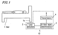
- FIG. 1 is a diagram illustrating the in-bed state detection system 10 .
- the in-bed state detection system 10 includes a load detection section 2 , an in-bed state determination section 3 , and a transmission section 4 .
- the load detection section 2 which detects the load applied on at least one leg 1a of a bed 1 , is disposed between that leg and the floor.
- a load signal representing the load detected by the load detection section 2 is sent to and analyzed by the in-bed state determination section 3 .
- the result of analysis is sent by the transmission section 4 to the outside of the room in which the bed 1 is placed.
- Figure 2 is a graph illustrating the load applied to a leg of a bed versus time. Specifically, Figure 2 illustrates a person getting in bed at time t1 and getting out of bed at time t2 .
- the in-bed state determination section 3 determines whether a person is in bed or out of bed based on the load signal detected by the load detection section 2 . If the detected load signal is equal to or greater than a threshold value A shown in Figure 2 , the in-bed state determination section 3 determines that the person is in bed; if the detected load signal is smaller than a threshold value A shown in Figure 2 , the in-bed state determination section 3 determines that the person is out of bed.
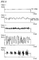
- Figure 3 is a set of graphs illustrating loads applied versus time in various in-bed states.
- pattern 1 shows a "fast asleep” state, where the body of the person in bed is in substantially no motion.
- Pattern 2 shows a "lacking sleep” state, where the magnitude of the detected load signal undergoes a periodic variation (i.e., the person in bed keeps repositioning through turning over, etc.).
- Pattern 3 shows a "convulsive” state, where the person in bed is having a convulsion (i.e., the body of the person is making minute movements).
- Pattern 4 shows a "frantic” (under an unperiodic stroke) state, where the person in bed is having an unperiodic stroke or moving about violently.
- Pattern 5 shows a "periodic strokes" state, where the person in bed is having periodic strokes.
- the in-bed state determination section 3 determines at least one of the above-mentioned states based on the detected load signal.
- the in-bed state determination section 3 may include a first table, against which one of the above states is to be determined based on the amplitude and frequency of the detected load signal.
- the first table may indicate that a pattern satisfying the condition "A 1 ⁇ amplitude of the detected load signal ⁇ A 2 " and the condition "C 1 ⁇ frequency of the detected load signal ⁇ C 2 " is pattern 2 .
- the in-bed state determination section 3 determines that a person in bed whose sensed motion satisfies these conditions is in a "lacking sleep" state.
- the in-bed state determination section 3 may detect movement of the person in bed based on the magnitude of the absolute value of the detected load signal, and determine one of the above states based on the temporal distribution of the detected load signal.
- the load detection section 2 in Figure 1 may be disposed between a caster on a leg of the bed and the floor, a mechanism for detecting a load applied to a leg of the bed may alternatively be provided within the leg.
- the in-bed state determination section 3 and the signal transmission section 4 may be implemented as one integral means.
- FIG. 4 is a diagram illustrating the in-bed state detection system 20 .
- the in-bed state detection system 20 includes a load detection section 2 , an in-bed state determination section 3 , and a transmission section 4 .
- the in-bed state determination section 3 includes a microcomputer 32 (including an A/D convertor) for determination processing , and a memory 33 .
- the microcomputer 32 receives the load signal from the signal processing circuit 22 and determines the in-bed state based thereon.
- the in-bed state determination section 3 may include a differentiation process circuit 31 as illustrated in Figure 4.
- the differentiation process circuit 31 receives a load signal and subjects the load signal to differentiation by time, so as to send a resultant signal (hereinafter "differentiation signal") to the microcomputer 32 .
- the microcomputer 32 receives the differentiation signal and determines the in-bed state based thereon. Alternatively, the microcomputer 32 may determine the in-bed state based on the load signal.
- the differentiation of the load signal may be performed in the microcomputer 32 instead of the differentiation process circuit 31 .
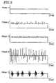
- Figure 5 is a set of graphs illustrating exemplary waveforms versus time in various in-bed states, where the waveforms are obtained by differentiating a load signal by time.
- pattern 1 shows a "fast asleep” state
- pattern 2 shows a "lacking sleep” state
- pattern 3 shows a “convulsive” state
- pattern 4 shows a "frantic” (under an unperiodic stroke) state
- pattern 5 shows a "periodic strokes” state.
- the microcomputer 32 determines at least one of the above-mentioned states based on the waveform (pulses) obtained by differentiating the load signal by time via the differentiation process circuit 31 .
- the memory 33 may include a second table against which the microcomputer 32 determines at least one of the above-mentioned patterns based on the output intensity and temporal distribution of the pulses.
- the second table may indicate that a pattern satisfying the condition "I 1 ⁇ output intensity ⁇ I 2 " and the condition "D 1 ⁇ temporal distribution density ⁇ D 2 " is pattern 2.
- the microcomputer 32 determines that a person in bed whose sensed motion satisfies these conditions is in a "lacking sleep" state.
- the microcomputer 32 calls the table stored in the memory 33 to compare the output intensity and the temporal distribution of the aforementioned pulses against the table, thereby determining a state which corresponds to the specific output intensity and temporal distribution of the pulses.
- the microcomputer 32 may detect the in-bed state based on the differentiation signal and the load signal. Such an in-bed state detection system can accurately determine the in-bed state.
- the memory 33 includes the first table (according to Example 1) as well as the second table.
- the results determined by the microcomputer 32 are output by a determination data transmission circuit 41 in the transmission section 4 ( Figure 4 ) to a designated location outside of the room in which the bed 1 is placed.
- the result of determination by the microcomputer 32 may be a digital value.
- the in-bed state detection system 20 may include an alarm section 5 .
- the alarm section 5 indicates the in-bed state of a person to another via sounds (defined herein as encompassing any audible sounds including voices, etc.) and/or light, based on the result of determination by the microcomputer 32 .
- the indication or alarm via sounds and/or light can be continuous or intermittent.
- the in-bed state detection system 20 may also include an alarm disengagement section for stopping the alarm after the in-bed state of the person in bed has been confirmed by another.
- the load sensor 21 e.g., a load cell, may be disposed between a caster on a leg of the bed and the floor.
- a mechanism for detecting a load applied to a leg of the bed may alternatively be provided within the leg.
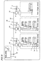
- FIG. 6 is a diagram illustrating the in-bed state detection system 50 .
- the in-bed state detection system 50 includes load detection sections 2 , in-bed state determination sections 3 , transmission sections 4 , alarm sections 5 , alarm disengagement sections 6 , and a central control unit 51 .
- the load detection sections 2 , the in-bed state determination sections 3 , the transmission sections 4 , the alarm sections 5 , and the alarm disengagement sections 6 are of the same construction as that of their corresponding components in Examples 1 and/or 2. It is assumed that the in-bed state detection system 50 is installed in a hospital, a facility for the aged, etc., having a plurality of rooms, with the central control unit 51 being located in a room other than any of the rooms accommodating one or more beds.
- Each load detection section 2 is located in a bed room accommodating at least one bed. More specifically, the load detection section 2 , which detects the load applied on at least one leg (i.e., leg 1a ) of the bed 1 , is disposed between that leg and the floor. All or part of the load detection section 2 is located inside or outside the room. As in Examples 1 and 2, each in-bed state determination section 3 is capable of determining the respective in-bed states based on load signals output from a plurality of load detection sections 2 . The results of determination are sent by each transmission section 4 to the outside of the corresponding room. Specifically, the results of determination are sent to the central control unit 51 via an IFU (interface unit) 52 and wiring 53 (e.g., Ethernet).
- IFU interface unit
- the central control unit 51 includes a monitor (not shown) indicating the in-bed states of the respective patients.
- the central control unit 51 may be located in a nurse station for monitoring the patients. Nurses, doctors, and others standing by in the nurse station can know the in-bed states of the respective patients in real time.
- An alarm section 5 may be provided in the vicinity of the central control unit 51 for indicating the results of determination.
- the alarm section 5 using sounds and/or light, indicates any state that may be hazardous to the life of each patient, e.g., a "convulsive” state, a "frantic” (under an unperiodic stroke) state, or a "periodic strokes” state, to those standing by in the nurse station.
- the indication or alarm via sounds and/or light can be made continuously or intermittently.
- the alarm disengagement sections 6 for stopping the alarm may be located in a hallway between the nurse station and the rooms accommodating beds for patients. Thus, once a doctor, a nurse, or the like, has directly confirmed the state of a patient, he or she can stop the alarm indicated by the alarm section 5 via the alarm disengagement section 6 located in the hallway, without returning to the nurse station.
- monitor cameras or the like for indirectly monitoring the states of the respective patients may be provided in each room.
- the central control unit 51 may be provided with a function of stopping alarms.
- a doctor, a nurse, or the like has confirmed the safe condition of a patient via images from a monitor camera displayed on a monitor display located in the nurse center or the like, he or she can stop the alarm by means of the central control unit 51 .
- the monitor cameras and the monitor display may be arranged so as to automatically begin displaying a patient who has entered a state that may be hazardous to the life of each patient, e.g., a "convulsive” state, a "frantic” (under an unperiodic stroke) state, or a "periodic strokes” state.
- a state that may be hazardous to the life of each patient e.g., a "convulsive” state, a "frantic” (under an unperiodic stroke) state, or a "periodic strokes” state.
- an electromagnetic signal transmitter and an electromagnetic signal receiver may be used as the transmission section 4 for transmitting results of determination by the in-bed state determination section 3 to the outside.
- Such an electromagnetic signal transmitter may be disposed on the bed frame or the bed body.
- the electromagnetic signal transmitter receives the result of determination from the in-bed state determination section 3 and transmits it to the electromagnetic signal receiver disposed, for example, on the ceiling, wall, or the floor of the room.
- the result of determination received by the electromagnetic signal receiver is sent to the central control unit 51 via the IFU 52 . This arrangement allows for a substantially unrestricted layout of beds within each room.
- the in-bed state detection system of the present invention can detect the load applied to each of any two or more legs of the bed and determine the in-bed state based on these load values.
- the in-bed state detection system determines the in-bed state of a person in bed based on a detected load signal, and transmits the result of determination to the outside of the room in which the bed is placed. This eliminates the need for another person to stand by in the room in order to monitor the state of the person who is in bed.
- the in-bed state detection system can include an alarm section for indicating or alarming any of the aforementioned in-bed states via sounds and/or light. Therefore, even if a patient encounters a stroke or convulsion so that he or she cannot even utter a sound for help, the alarm section can call for help instead of the patient.
Landscapes
- Business, Economics & Management (AREA)
- Emergency Management (AREA)
- Physics & Mathematics (AREA)
- General Physics & Mathematics (AREA)
- Measuring And Recording Apparatus For Diagnosis (AREA)
- Invalid Beds And Related Equipment (AREA)
Applications Claiming Priority (3)
| Application Number | Priority Date | Filing Date | Title |
|---|---|---|---|
| JP25198197 | 1997-09-17 | ||
| JP251981/97 | 1997-09-17 | ||
| JP25198197 | 1997-09-17 |
Publications (3)
| Publication Number | Publication Date |
|---|---|
| EP0903707A2 true EP0903707A2 (de) | 1999-03-24 |
| EP0903707A3 EP0903707A3 (de) | 1999-08-25 |
| EP0903707B1 EP0903707B1 (de) | 2004-02-04 |
Family
ID=17230889
Family Applications (1)
| Application Number | Title | Priority Date | Filing Date |
|---|---|---|---|
| EP98117439A Expired - Lifetime EP0903707B1 (de) | 1997-09-17 | 1998-09-15 | Bettbelegungs-Erfassungssystem |
Country Status (4)
| Country | Link |
|---|---|
| US (1) | US6239706B1 (de) |
| EP (1) | EP0903707B1 (de) |
| KR (1) | KR100310928B1 (de) |
| DE (2) | DE69821422T2 (de) |
Cited By (2)
| Publication number | Priority date | Publication date | Assignee | Title |
|---|---|---|---|---|
| EP1775686A1 (de) * | 2005-10-11 | 2007-04-18 | Quick Sensor NV | Belegungsüberwachungssystem |
| US8508219B2 (en) | 2008-04-30 | 2013-08-13 | National Institute Of Advanced Industrial Science And Technology | Object state detection apparatus and method |
Families Citing this family (50)
| Publication number | Priority date | Publication date | Assignee | Title |
|---|---|---|---|---|
| CA2327000C (en) * | 2000-11-27 | 2006-05-09 | Terry Cassaday | Chair or bed member having data storage |
| US6825769B2 (en) * | 2001-09-14 | 2004-11-30 | Koninklijke Philips Electronics N.V. | Automatic shut-off light system when user sleeps |
| US6788206B1 (en) | 2002-09-05 | 2004-09-07 | Donald A. Edwards | Patient monitoring system |
| SE0203483D0 (sv) * | 2002-11-21 | 2002-11-21 | Wespot Ab | Method and device for fall detection |
| US8512221B2 (en) * | 2003-02-28 | 2013-08-20 | Consolidated Research Of Richmond, Inc. | Automated treatment system for sleep |
| EP1601329A4 (de) * | 2003-02-28 | 2010-08-25 | Cons Res Of Richmond Inc | Automatisches system zur behandlung von schlaflosigkeit |
| JP3960298B2 (ja) * | 2003-11-19 | 2007-08-15 | 株式会社デンソー | 寝姿及び体位検出装置 |
| JP4809779B2 (ja) * | 2004-02-05 | 2011-11-09 | アーリーセンス・リミテッド | 呼吸に現れる臨床的発症の予測及びモニタリング技術 |
| US8403865B2 (en) | 2004-02-05 | 2013-03-26 | Earlysense Ltd. | Prediction and monitoring of clinical episodes |
| US7314451B2 (en) | 2005-04-25 | 2008-01-01 | Earlysense Ltd. | Techniques for prediction and monitoring of clinical episodes |
| US20070118054A1 (en) * | 2005-11-01 | 2007-05-24 | Earlysense Ltd. | Methods and systems for monitoring patients for clinical episodes |
| US8942779B2 (en) | 2004-02-05 | 2015-01-27 | Early Sense Ltd. | Monitoring a condition of a subject |
| US8491492B2 (en) | 2004-02-05 | 2013-07-23 | Earlysense Ltd. | Monitoring a condition of a subject |
| US20060019224A1 (en) * | 2004-07-23 | 2006-01-26 | Pics, Inc. | Insomnia assessment and treatment device and method |
| US7253366B2 (en) * | 2004-08-09 | 2007-08-07 | Hill-Rom Services, Inc. | Exit alarm for a hospital bed triggered by individual load cell weight readings exceeding a predetermined threshold |
| KR100712198B1 (ko) * | 2005-02-17 | 2007-04-30 | 재단법인서울대학교산학협력재단 | 무구속 무게감지 기반 수면구조 분석 장치 |
| DE102005011706A1 (de) * | 2005-03-11 | 2006-09-28 | Klugmann, Gerhard | Neuartiges Verfahren und Vorrichtung zur Fernüberwachung von Pflegeplätzen |
| US20090051549A1 (en) * | 2005-03-24 | 2009-02-26 | Showa Denko K.K | Bed load detector |
| JP5208732B2 (ja) | 2005-06-10 | 2013-06-12 | ヒル−ロム サービシーズ,インコーポレイティド | 患者支持装置内の与圧袋の制御手段 |
| JP4514717B2 (ja) * | 2006-01-20 | 2010-07-28 | パラマウントベッド株式会社 | 離床予測・検知システムを備えた寝台装置 |
| US7849545B2 (en) * | 2006-11-14 | 2010-12-14 | Hill-Rom Industries Sa | Control system for hospital bed mattress |
| WO2009138976A2 (en) * | 2008-05-12 | 2009-11-19 | Earlysense Ltd | Monitoring, predicting and treating clinical episodes |
| US8585607B2 (en) * | 2007-05-02 | 2013-11-19 | Earlysense Ltd. | Monitoring, predicting and treating clinical episodes |
| US9883809B2 (en) | 2008-05-01 | 2018-02-06 | Earlysense Ltd. | Monitoring, predicting and treating clinical episodes |
| US8882684B2 (en) | 2008-05-12 | 2014-11-11 | Earlysense Ltd. | Monitoring, predicting and treating clinical episodes |
| US10335060B1 (en) | 2010-06-19 | 2019-07-02 | Dp Technologies, Inc. | Method and apparatus to provide monitoring |
| US8783114B2 (en) * | 2010-07-14 | 2014-07-22 | Healthsense, Inc. | Occupancy sensor |
| US8717181B2 (en) | 2010-07-29 | 2014-05-06 | Hill-Rom Services, Inc. | Bed exit alert silence with automatic re-enable |
| US10292625B2 (en) | 2010-12-07 | 2019-05-21 | Earlysense Ltd. | Monitoring a sleeping subject |
| US9013313B2 (en) * | 2011-01-18 | 2015-04-21 | Alan Paine | Bed pre-exit patient monitor |
| US9192326B2 (en) | 2011-07-13 | 2015-11-24 | Dp Technologies, Inc. | Sleep monitoring system |
| US9459597B2 (en) * | 2012-03-06 | 2016-10-04 | DPTechnologies, Inc. | Method and apparatus to provide an improved sleep experience by selecting an optimal next sleep state for a user |
| US10791986B1 (en) | 2012-04-05 | 2020-10-06 | Dp Technologies, Inc. | Sleep sound detection system and use |
| US10292605B2 (en) | 2012-11-15 | 2019-05-21 | Hill-Rom Services, Inc. | Bed load cell based physiological sensing systems and methods |
| US9474876B1 (en) | 2012-12-14 | 2016-10-25 | DPTechnologies, Inc. | Sleep aid efficacy |
| WO2014152550A2 (en) | 2013-03-15 | 2014-09-25 | Stryker Corporation | Medical support apparatus |
| US10376214B2 (en) | 2013-03-15 | 2019-08-13 | Stryker Corporation | Patient support apparatus with patient information sensors |
| US9320444B2 (en) | 2013-03-15 | 2016-04-26 | Stryker Corporation | Patient support apparatus with patient information sensors |
| US9594354B1 (en) | 2013-04-19 | 2017-03-14 | Dp Technologies, Inc. | Smart watch extended system |
| US11963792B1 (en) | 2014-05-04 | 2024-04-23 | Dp Technologies, Inc. | Sleep ecosystem |
| EP2995242B1 (de) | 2014-09-11 | 2023-11-15 | Hill-Rom S.A.S. | Patientenliegevorrichtung |
| CA2960740C (en) * | 2014-10-17 | 2025-10-07 | Stryker Corporation | MOTION MONITORING PERSONAL SUPPORT DEVICES |
| US9468399B2 (en) | 2014-12-09 | 2016-10-18 | SensaRx, LLC | Detection of changes from a seated or lying body position by sensing body angle |
| US11883188B1 (en) | 2015-03-16 | 2024-01-30 | Dp Technologies, Inc. | Sleep surface sensor based sleep analysis system |
| US10078952B2 (en) * | 2015-11-02 | 2018-09-18 | Patrick John O'Keefe, JR. | Bed check device and method of use |
| US9679462B1 (en) | 2015-12-20 | 2017-06-13 | Christopher Robertson | Wireless wake-up alarm with occupant-sensing apparatus |
| EP3205268B1 (de) | 2016-02-11 | 2023-10-25 | Hill-Rom Services, Inc. | Krankenhausbett |
| US11813203B2 (en) | 2016-11-28 | 2023-11-14 | Verb Surgical Inc. | Robotic surgical table with relatively high resonant frequency structure to reduce efficiency of energy transmission between attached robotic arms |
| US11793455B1 (en) | 2018-10-15 | 2023-10-24 | Dp Technologies, Inc. | Hardware sensor system for controlling sleep environment |
| US12527524B2 (en) | 2020-03-30 | 2026-01-20 | Hill-Rom Services, Inc. | Bed-based ballistocardiogram apparatus and method |
Family Cites Families (13)
| Publication number | Priority date | Publication date | Assignee | Title |
|---|---|---|---|---|
| US4263586A (en) * | 1976-08-20 | 1981-04-21 | Noel Nicholas | Pressure operated electric switch and alarm system using such switch |
| US4179692A (en) * | 1977-05-05 | 1979-12-18 | Vance Dwight A | Apparatus to indicate when a patient has evacuated a bed or demonstrates a restless condition |
| US4320766A (en) * | 1979-03-13 | 1982-03-23 | Instrumentarium Oy | Apparatus in medicine for the monitoring and or recording of the body movements of a person on a bed, for instance of a patient |
| US4633237A (en) * | 1984-07-11 | 1986-12-30 | Kenneth A. Tucknott | Patient bed alarm system |
| US4738264A (en) * | 1985-03-25 | 1988-04-19 | Carl Orlando | Heart and breathing alarm monitor |
| US4638307A (en) * | 1985-10-15 | 1987-01-20 | Swartout Willson C | Patient position monitoring system |
| US4657026A (en) * | 1986-07-14 | 1987-04-14 | Tagg James R | Apnea alarm systems |
| WO1991013585A1 (en) * | 1990-03-09 | 1991-09-19 | Matsushita Electric Industrial Co., Ltd. | Sleep detecting device |
| JP2906075B2 (ja) | 1990-05-28 | 1999-06-14 | 戸田工業株式会社 | 磁気記録用磁性粒子粉末の製造法 |
| JPH04153799A (ja) | 1990-10-17 | 1992-05-27 | Fuji Electric Co Ltd | 所在場所検出装置および所在場所監視システム |
| US5276432A (en) * | 1992-01-15 | 1994-01-04 | Stryker Corporation | Patient exit detection mechanism for hospital bed |
| US5590650A (en) * | 1994-11-16 | 1997-01-07 | Raven, Inc. | Non-invasive medical monitor system |
| US5853005A (en) * | 1996-05-02 | 1998-12-29 | The United States Of America As Represented By The Secretary Of The Army | Acoustic monitoring system |
-
1998
- 1998-09-15 DE DE69821422T patent/DE69821422T2/de not_active Expired - Lifetime
- 1998-09-15 DE DE0903707T patent/DE903707T1/de active Pending
- 1998-09-15 EP EP98117439A patent/EP0903707B1/de not_active Expired - Lifetime
- 1998-09-16 US US09/154,493 patent/US6239706B1/en not_active Expired - Lifetime
- 1998-09-16 KR KR1019980038145A patent/KR100310928B1/ko not_active Expired - Lifetime
Cited By (3)
| Publication number | Priority date | Publication date | Assignee | Title |
|---|---|---|---|---|
| EP1775686A1 (de) * | 2005-10-11 | 2007-04-18 | Quick Sensor NV | Belegungsüberwachungssystem |
| EP2154658A1 (de) | 2005-10-11 | 2010-02-17 | Quick Sensor NV | Belegungsüberwachungssystem |
| US8508219B2 (en) | 2008-04-30 | 2013-08-13 | National Institute Of Advanced Industrial Science And Technology | Object state detection apparatus and method |
Also Published As
| Publication number | Publication date |
|---|---|
| KR100310928B1 (ko) | 2001-12-28 |
| KR19990029820A (ko) | 1999-04-26 |
| EP0903707B1 (de) | 2004-02-04 |
| US6239706B1 (en) | 2001-05-29 |
| EP0903707A3 (de) | 1999-08-25 |
| DE903707T1 (de) | 1999-12-09 |
| DE69821422T2 (de) | 2004-12-30 |
| DE69821422D1 (de) | 2004-03-11 |
Similar Documents
| Publication | Publication Date | Title |
|---|---|---|
| US6239706B1 (en) | In-bed state detection system | |
| US8620625B2 (en) | Above bed sensor | |
| JP3941227B2 (ja) | 異常監視装置 | |
| JP6261879B2 (ja) | 使用者離床予測システム、方法および装置 | |
| US5107845A (en) | Method and device for monitoring human respiration | |
| US8823527B2 (en) | Consciousness monitoring | |
| JP2024509427A (ja) | 監視用のセンサ及びシステム | |
| KR101712191B1 (ko) | 환자 낙상예방 모니터링 장치 | |
| JP2009279076A (ja) | 監視システム | |
| KR20090119157A (ko) | 유비쿼터스 센서 네트워크 및 멀티 센서 기반의 생리 현상모니터링 시스템 | |
| CN113384247A (zh) | 照护系统与自动照护方法 | |
| EP3797679A1 (de) | Inkontinenzdetektion mit echtzeitstandortinformationen | |
| WO2015172246A1 (en) | Multifunctional monitoring system comprising sensors attached to an absorbent article | |
| JP6288755B2 (ja) | 監視システム、及び、活動量計 | |
| JP3231282B2 (ja) | 在床状態検知システム | |
| JP3459202B2 (ja) | 行動判定装置、ケアシステム、ケア住宅およびプログラム記録媒体 | |
| JP2000271098A (ja) | 介護システム | |
| JP3352935B2 (ja) | 離床在床検知システム、監視システム | |
| JP3376438B2 (ja) | 在床検知装置およびその検知方法 | |
| JP2024504056A (ja) | 監視用のセンサ及びシステム | |
| JP2000325409A (ja) | 位置特定装置および警告システム | |
| JPWO2020071374A1 (ja) | 状態監視装置および状態監視方法 | |
| WO2021085925A1 (ko) | 웨이크-업 감지 장치 | |
| JP2008242687A (ja) | 睡眠判定方法および睡眠見守りシステム | |
| JPH09327442A (ja) | 高齢者介護補助システム |
Legal Events
| Date | Code | Title | Description |
|---|---|---|---|
| PUAI | Public reference made under article 153(3) epc to a published international application that has entered the european phase |
Free format text: ORIGINAL CODE: 0009012 |
|
| 17P | Request for examination filed |
Effective date: 19990111 |
|
| AK | Designated contracting states |
Kind code of ref document: A2 Designated state(s): DE FR GB |
|
| AX | Request for extension of the european patent |
Free format text: AL;LT;LV;MK;RO;SI |
|
| EL | Fr: translation of claims filed | ||
| PUAL | Search report despatched |
Free format text: ORIGINAL CODE: 0009013 |
|
| AK | Designated contracting states |
Kind code of ref document: A3 Designated state(s): AT BE CH CY DE DK ES FI FR GB GR IE IT LI LU MC NL PT SE |
|
| AX | Request for extension of the european patent |
Free format text: AL;LT;LV;MK;RO;SI |
|
| RIC1 | Information provided on ipc code assigned before grant |
Free format text: 6G 08B 21/00 A, 6A 61B 5/11 B |
|
| DET | De: translation of patent claims | ||
| AKX | Designation fees paid |
Free format text: DE FR GB |
|
| 17Q | First examination report despatched |
Effective date: 20010801 |
|
| GRAP | Despatch of communication of intention to grant a patent |
Free format text: ORIGINAL CODE: EPIDOSNIGR1 |
|
| GRAS | Grant fee paid |
Free format text: ORIGINAL CODE: EPIDOSNIGR3 |
|
| GRAA | (expected) grant |
Free format text: ORIGINAL CODE: 0009210 |
|
| AK | Designated contracting states |
Kind code of ref document: B1 Designated state(s): DE FR GB |
|
| REG | Reference to a national code |
Ref country code: GB Ref legal event code: FG4D |
|
| REF | Corresponds to: |
Ref document number: 69821422 Country of ref document: DE Date of ref document: 20040311 Kind code of ref document: P |
|
| ET | Fr: translation filed | ||
| PLBE | No opposition filed within time limit |
Free format text: ORIGINAL CODE: 0009261 |
|
| STAA | Information on the status of an ep patent application or granted ep patent |
Free format text: STATUS: NO OPPOSITION FILED WITHIN TIME LIMIT |
|
| 26N | No opposition filed |
Effective date: 20041105 |
|
| REG | Reference to a national code |
Ref country code: FR Ref legal event code: PLFP Year of fee payment: 19 |
|
| REG | Reference to a national code |
Ref country code: FR Ref legal event code: PLFP Year of fee payment: 20 |
|
| PGFP | Annual fee paid to national office [announced via postgrant information from national office to epo] |
Ref country code: FR Payment date: 20170810 Year of fee payment: 20 Ref country code: DE Payment date: 20170321 Year of fee payment: 20 Ref country code: GB Payment date: 20170913 Year of fee payment: 20 |
|
| REG | Reference to a national code |
Ref country code: DE Ref legal event code: R071 Ref document number: 69821422 Country of ref document: DE |
|
| REG | Reference to a national code |
Ref country code: GB Ref legal event code: PE20 Expiry date: 20180914 |
|
| PG25 | Lapsed in a contracting state [announced via postgrant information from national office to epo] |
Ref country code: GB Free format text: LAPSE BECAUSE OF EXPIRATION OF PROTECTION Effective date: 20180914 |