EP0903524B1 - Dispositif actionné par flotteur - Google Patents
Dispositif actionné par flotteur Download PDFInfo
- Publication number
- EP0903524B1 EP0903524B1 EP98307613A EP98307613A EP0903524B1 EP 0903524 B1 EP0903524 B1 EP 0903524B1 EP 98307613 A EP98307613 A EP 98307613A EP 98307613 A EP98307613 A EP 98307613A EP 0903524 B1 EP0903524 B1 EP 0903524B1
- Authority
- EP
- European Patent Office
- Prior art keywords
- float
- chamber
- lever
- output lever
- valve
- Prior art date
- Legal status (The legal status is an assumption and is not a legal conclusion. Google has not performed a legal analysis and makes no representation as to the accuracy of the status listed.)
- Expired - Lifetime
Links
- 230000007246 mechanism Effects 0.000 claims description 28
- 239000007788 liquid Substances 0.000 claims description 8
- 238000000034 method Methods 0.000 claims description 6
- 230000008569 process Effects 0.000 claims description 6
- 230000004044 response Effects 0.000 claims description 4
- 239000012530 fluid Substances 0.000 claims description 3
- 230000009471 action Effects 0.000 description 2
- 230000008901 benefit Effects 0.000 description 2
- 230000000630 rising effect Effects 0.000 description 2
- 238000013459 approach Methods 0.000 description 1
- 230000008859 change Effects 0.000 description 1
- 238000009833 condensation Methods 0.000 description 1
- 230000005494 condensation Effects 0.000 description 1
- 238000001816 cooling Methods 0.000 description 1
- 230000001934 delay Effects 0.000 description 1
- 238000013461 design Methods 0.000 description 1
- 238000006073 displacement reaction Methods 0.000 description 1
- 230000000694 effects Effects 0.000 description 1
- 230000005484 gravity Effects 0.000 description 1
- 238000002156 mixing Methods 0.000 description 1
- 230000000737 periodic effect Effects 0.000 description 1
- 238000005086 pumping Methods 0.000 description 1
- 230000000717 retained effect Effects 0.000 description 1
- 238000007789 sealing Methods 0.000 description 1
- 238000005728 strengthening Methods 0.000 description 1
- 238000012546 transfer Methods 0.000 description 1
- 238000013022 venting Methods 0.000 description 1
Images


Classifications
-
- F—MECHANICAL ENGINEERING; LIGHTING; HEATING; WEAPONS; BLASTING
- F04—POSITIVE - DISPLACEMENT MACHINES FOR LIQUIDS; PUMPS FOR LIQUIDS OR ELASTIC FLUIDS
- F04B—POSITIVE-DISPLACEMENT MACHINES FOR LIQUIDS; PUMPS
- F04B49/00—Control, e.g. of pump delivery, or pump pressure of, or safety measures for, machines, pumps, or pumping installations, not otherwise provided for, or of interest apart from, groups F04B1/00 - F04B47/00
- F04B49/02—Stopping, starting, unloading or idling control
- F04B49/025—Stopping, starting, unloading or idling control by means of floats
-
- F—MECHANICAL ENGINEERING; LIGHTING; HEATING; WEAPONS; BLASTING
- F16—ENGINEERING ELEMENTS AND UNITS; GENERAL MEASURES FOR PRODUCING AND MAINTAINING EFFECTIVE FUNCTIONING OF MACHINES OR INSTALLATIONS; THERMAL INSULATION IN GENERAL
- F16K—VALVES; TAPS; COCKS; ACTUATING-FLOATS; DEVICES FOR VENTING OR AERATING
- F16K31/00—Actuating devices; Operating means; Releasing devices
- F16K31/12—Actuating devices; Operating means; Releasing devices actuated by fluid
- F16K31/18—Actuating devices; Operating means; Releasing devices actuated by fluid actuated by a float
-
- F—MECHANICAL ENGINEERING; LIGHTING; HEATING; WEAPONS; BLASTING
- F04—POSITIVE - DISPLACEMENT MACHINES FOR LIQUIDS; PUMPS FOR LIQUIDS OR ELASTIC FLUIDS
- F04B—POSITIVE-DISPLACEMENT MACHINES FOR LIQUIDS; PUMPS
- F04B53/00—Component parts, details or accessories not provided for in, or of interest apart from, groups F04B1/00 - F04B23/00 or F04B39/00 - F04B47/00
- F04B53/10—Valves; Arrangement of valves
-
- F—MECHANICAL ENGINEERING; LIGHTING; HEATING; WEAPONS; BLASTING
- F05—INDEXING SCHEMES RELATING TO ENGINES OR PUMPS IN VARIOUS SUBCLASSES OF CLASSES F01-F04
- F05B—INDEXING SCHEME RELATING TO WIND, SPRING, WEIGHT, INERTIA OR LIKE MOTORS, TO MACHINES OR ENGINES FOR LIQUIDS COVERED BY SUBCLASSES F03B, F03D AND F03G
- F05B2210/00—Working fluid
- F05B2210/10—Kind or type
- F05B2210/11—Kind or type liquid, i.e. incompressible
-
- Y—GENERAL TAGGING OF NEW TECHNOLOGICAL DEVELOPMENTS; GENERAL TAGGING OF CROSS-SECTIONAL TECHNOLOGIES SPANNING OVER SEVERAL SECTIONS OF THE IPC; TECHNICAL SUBJECTS COVERED BY FORMER USPC CROSS-REFERENCE ART COLLECTIONS [XRACs] AND DIGESTS
- Y10—TECHNICAL SUBJECTS COVERED BY FORMER USPC
- Y10S—TECHNICAL SUBJECTS COVERED BY FORMER USPC CROSS-REFERENCE ART COLLECTIONS [XRACs] AND DIGESTS
- Y10S417/00—Pumps
Definitions
- This invention relates to a float operated device which operates at high pressure, such as a pressure powered pump or a condensate trap.
- high pressure means a pressure in excess of 5 bar and refers to the internal pressure in the housing of the device, to which pressure the float is subjected.
- Pressure powered pumps are used in steam systems in order to raise condensate to a condensate return system from which the condensate is reintroduced to the steam generating boiler.
- Such pumps comprise a chamber in which the condensate accumulates, to be periodically discharged by the periodic admission of steam and venting of the chamber under the control of a float which is responsive to the level of condensate in the chamber.
- US-A-5141405 discloses a float operated device in the form of a pressure powered pump which has a toggle mechanism comprising an input lever and an output lever which are mounted for pivotable movement on a common support, and resilient means which acts between a first point on the input lever and a second point on the output lever, the output lever being pivotable between limit positions and the input lever being pivotable between a first position, in which the resilient means acts to bias the output lever into one of its limit positions, a dead point in which the first and second points and the mounting location of the output lever lie on a common straight line, and a second position, in which the resilient means acts to bias the output lever into the other of its limit positions.
- the input and output levers are mounted on the common support for pivotable movement about a common axis. Consequently, the toggle mechanism suffers from the disadvantage that it exerts its greatest resistance to movement of the float when the float is at its end positions. This means that substantially the entire buoyancy (or weight) of the float is utilised to overcome the resistance imposed by the toggle mechanism. As a result, there is no surplus energy which can be utilised to perform other operations, such as the opening of an outlet valve for process fluid.
- the input lever and the output lever are mounted on the common support for pivotable movement about spaced axes.
- the force required to displace the input lever from either the first of second position to the dead point increases continuously as the input lever approaches the dead point.
- the limit positions of the output lever are preferably defined by stops which are engagable by the output lever.
- the output lever may be connected to a valve mechanism.
- the toggle mechanism defined above When used in a float-operated pressure powered pump, the toggle mechanism defined above has the advantage that the initial movement of the float from either of its end positions requires little force, so that the initial movement of the float can be employed, for example, to open an outlet valve for controlling the flow of process liquid from the chamber of the pump.
- the device may comprise a float, capable of withstanding a high pressure, which is supported by a linkage for pivotable movement upwardly and downwardly within a chamber in response to the level of liquid in the chamber, the linkage being connected to actuating means which includes the toggle mechanism and which is operable by movement of the float to actuate control means for controlling the flow into and/or out of the chamber.
- the rising float may operate an outlet valve before steam is admitted to the chamber, the condensate then being discharged through the outlet under the pressure at the inlet. If the pressure head is insufficient to discharge the condensate, the float will rise further, and steam will be admitted to the chamber to force the condensate out under pressure.
- the pressure powered pump is normally situated at the lowest point in the steam system. It is usually floor-mounted. Sometimes the heat exchanger, or other component of the steam system from which condensate is supplied to the pressure powered pump, is only a small distance above the floor, and consequently the filling head for the pump is too small to produce an adequate filling rate for the pump chamber. It is therefore desirable for the pressure powered pump to operate reliably with a small change in liquid level within the chamber between the end positions of the float. However, in conventional pressure powered pumps which use a spherical float, the diameter of the float itself influences the overall height of the pump chamber.
- the size of the float itself is dictated by the need to provide adequate buoyancy to operate the toggle mechanism in the rising direction of the float, and adequate weight to operate the toggle mechanism in the reverse direction as the float falls.
- Spherical floats have conventionally been used in high pressure devices such as pressure powered pumps and condensate traps because a spherical shape is best able to withstand the high pressure to which they are subjected in use.
- the ratio (the "aspect ratio") of the maximum dimension of the float in the horizontal direction to the maximum direction of the float in the vertical direction may be not less than 2, and preferably is in the range 2 to 3.5.
- a spherical float as used in the prior art has an aspect ratio of 1.
- a float with an aspect ratio which is not less than 2 consequently has a relatively low profile and occupies a small vertical space. This means that the chamber, and consequently the device itself, may be reduced in height by comparison with an equivalent device employing a spherical float.
- the float may comprise a single float element having a flattened shape, for example the shape of an oblate spheroid or of a flattened cylinder disposed with its axis vertical.
- the float may be made up of a plurality of float elements disposed so that the aspect ratio of the float as a whole is not less than 2.
- the float may comprise a plurality of spherical float elements disposed in a common horizontal plane, possibly in a circular array.
- the float may comprise two float elements each in the form of a horizontally disposed cylinder having hemispherical ends, the two float elements lying side-by-side.
- the linkage may comprise a parallelogram linkage having two levers which each interconnect the float to a fixed support, one of the levers comprising the input lever of the toggle mechanism.
- One of the levers is connected to the top of the float and the other is connected to the bottom.
- the levers may be cranked to enable them to clear the float when the float is at its end positions.
- the actuating means may be operatively connected to an operating valve arrangement for controlling the flow of a motive fluid into and out of the chamber.
- the linkage may be connected to an outlet valve for controlling the flow of liquid to be discharged from the chamber.
- the horizontal projection of the float may have an area which is not less than 50%, and more preferably not less than 60% of the maximum horizontal cross-section of the chamber.
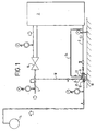
- the system shown in Figure 1 comprises steam utilization equipment represented as a heat exchanger 2 which receives process steam passing through a pipe 4 from a steam generating boiler. Heat transfer takes place in the heat exchanger 2, and some of the steam condenses and flows into a condensate pipe 6, which is connected to the condensate inlet 8 of a pressure powered pump 10. The outlet 12 of the pump 10 is connected to a condensate return system 14.
- steam utilization equipment represented as a heat exchanger 2 which receives process steam passing through a pipe 4 from a steam generating boiler. Heat transfer takes place in the heat exchanger 2, and some of the steam condenses and flows into a condensate pipe 6, which is connected to the condensate inlet 8 of a pressure powered pump 10.
- the outlet 12 of the pump 10 is connected to a condensate return system 14.
- Steam flowing through the pipe 4 is initially at high pressure, but this pressure is reduced by a control valve 16 so that the steam entering the heat exchanger 2 is at a pressure, and therefore temperature, suitable to the process taking place within it.
- Higher pressure steam at a pressure of at least 5 bar, for example in excess of 8 bar, is taken from the pipe 4 through a pipe 18 to a motive steam inlet 20 of the pump 10.
- An exhaust port 22 of the pump 10 is connected by a balance pipe 24 to the pipe 6.
- the pump is shown in greater detail in Figures 2 to 6.
- the pump comprises a housing 26 having an end cap 28 which between them define a chamber 30.
- a float 32 is situated within the chamber 30 and is supported by a parallelogram linkage comprising an upper lever 34 and a lower lever 36.
- the upper lever 34 is connected at a pivot location 38 to a support 40 which is secured to the end cap 28.
- the lower lever 36 is mounted at a pivot location 42 on a support 44 which is also secured to the end cap 28.
- the upper lever 34 serves as the input lever of a toggle mechanism 46.
- the mechanism 46 has an output lever 48 which is pivotably connected to the support 40 at a pivot location 50 which is spaced from the pivot location 38.
- the lever 34 has an arm 52, and a tension spring 54 acts between a first point 56 at the outer end of the arm 52, and a second point 58 on the output lever 48 at a position away from the pivot location 50.
- the output lever 48 carries an operating pin 60 for operation of a motive steam inlet valve 62 which controls the flow of steam from the pipe 18 through the inlet 20.
- the condensate inlet 8 is controlled by a flap valve 64 which cooperates with a seat 66.
- This valve is shown in greater detail in Figures 8 and 9. It will be appreciated from Figures 2 to 6 that the seat 66 is inclined with respect to the vertical.
- the flap valve has a circular main body 63, with an integrally formed pivot shaft 65 at its upper edge.
- the pivot shaft 65 extends tangentially of the main body and is retained at each end in respective gaps between the end cap 28 and the support 40, so that the main body 63 can swing into and out of contact with the seat 66 in response to the pressure difference between the chamber 30 and the inlet 8.
- the lower lever 36 is connected to an outlet valve 68 for controlling the flow of liquid through the condensate outlet 12.
- the valve 68 is shown in greater detail in Figure 7 and comprises a valve seat 70, an outer valve element 72 and an inner valve element 74.
- the valve seat 70 has a central bore 76, and the outer valve element 72 is movable into and out of sealing engagement with this bore 76.
- the outer valve element 72 has an opening 78, and the inner valve element 74 is movable into and out of contact with this opening 78.
- the inner valve element 74 is mounted on a stem 80 which is pivotably connected to the lever 36.
- the inner valve element 74 has a transverse pin 82 which engages in a longitudinally extending slot 84 formed in the outer valve element 72.
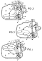
- FIG. 2 shows the pump in the condition in which no condensate is present in the chamber 30. Consequently, the float 32 is at its lowermost position.
- the valve 62 is closed and a corresponding valve (not shown in Figures 2 to 6 but visible at 96 in Figure 13) controlling the exhaust port 22 is open. Consequently, the pressure within the chamber 30 is the same as that at the condensate inlet port 8.
- the flap valve 64 hangs vertically so that any condensate flowing from the steam jacket from the heat exchanger 2 can pass (under gravity) into the chamber 30 without any pressure drop caused by a need to open the valve.
- the valve 68 is fully closed.
- Figure 3 shows the condition in which the chamber 30 has begun to fill with condensate.
- the float 32 has risen, causing the lower lever 36 to act on the stem 80 of the valve 68 to withdraw the inner valve element 74 from the opening 78.
- condensate is free to flow through the valve 68 through the condensate outlet 12 to the condensate return system 14.
- a non-return valve may be provided in the valve 68 to prevent backflow into the chamber 30.
- Figure 6 shows the condition in which the float 32 is in its uppermost position.
- the spring 54 has moved beyond the in-line condition of Figure 4, and consequently the toggle mechanism has switched, causing the output lever 48 to snap over rapidly to its other limit position.
- This causes the operating pin 60 to strike the actuating element 88 of the valve 62 so opening the motive steam inlet 20; at the same time, the exhaust 22 is closed. Steam rushes in through the motive steam inlet 20 to pressurize the chamber 30.
- This causes the flap valve 64 to close against the seat 66, and the increased pressure in the chamber 30 forces the condensate to be driven out through the fully open valve 68.
- a deflector 90 is fitted to the end cap 28 around the motive steam inlet 20.
- the purposes of this deflector 90 is to ensure that steam entering the chamber 30 is deflected upwardly away from the surface of condensate in the chamber 30 to avoid forced mixing of the steam and condensate. This delays the cooling, and consequent condensation, of the steam so that the pressure within the chamber 30 is maintained as the condensate is discharged through the valve 68.
- the float is in the form of an oblate spheroid, or flattened sphere.
- the profile of the float 32 is circular and there is only a relatively small clearance between the outer periphery of the float 32 and the wall of the chamber 30. This minimizes the free surface of condensate in the chamber 30 which further reduces heat exchange between the incoming motive steam and the condensate.
- the aspect ratio of the float 32 is approximately 2.4.
- the aspect ratio is less than 3.5, since it becomes increasingly difficult to design hollow floats with larger aspect ratios which are capable of withstanding the pressures which are likely to prevail in a pressure powered pump. Additional strength can be imparted by providing strengthening elements, such as honeycomb structures, within the float. Apart from the strength requirements, it is also necessary for the buoyancy and weight of the float to be sufficient to trip the toggle mechanism on both the upwards and downwards stroke of the float 32.
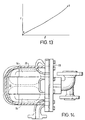
- Figure 10 represents the condition shown in Figure 2.
- the output lever 48 abuts the lower stop 92 and consequently upward movement of the float 32 is resisted by the spring 54.
- Figure 12 shows the condition immediately after that of Figure 11, in which the toggle mechanism has switched over, with the lever 48 snapping over into abutment with the upper stop 92.
- the toggle mechanism can be set up so that the buoyancy force required to raise the float 32 against the action of the spring 54 starts from a very low value, since the initial movement of the point C (56) is substantially perpendicular to the direction of the spring 54 (see Figure 2). Consequently, since the upwards movement of the float 32 is initially hardly resisted at all by the spring 54, all of the energy available from the movement of the float 32 can be applied to opening the valve 68 by lifting the inner valve element 74 from the opening 78. As the float continues to rise, the force needed to overcome the spring 54 gradually increases, and continues to increase until the dead point of the toggle mechanism.
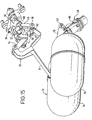
- Figures 14 and 15 show an alternative structure for the float 32.
- the float is made up of two float elements 94 which are rigidly connected together. Each float element is in the form of a cylinder having hemispherical ends. These float elements are disposed side-by-side with their longitudinal axes parallel to each other and lying in a horizontal plane. It will be appreciated from Figure 12 that, as mentioned above, the float 32 as a whole occupies a substantial proportion of the cross-sectional area of the chamber 30, so that the free surface of condensate is kept to a minimum to minimize heat exchange between the condensate and the incoming steam during a pumping cycle.
- the pressure powered pumps described above can be constructed with a relatively low profile as a result of the use of a low aspect ratio float. Also, since the condensate inlet valve 66 (and possibly any outlet non-return valve incorporated in the valve 68) are provided within the end cap 28, there is no need for separate non-return valves to be installed on each side of the pump.
- Another advantage of the pumps described above is that all working parts are mounted on the end cap 28, making servicing simpler.
Landscapes
- Engineering & Computer Science (AREA)
- General Engineering & Computer Science (AREA)
- Mechanical Engineering (AREA)
- Jet Pumps And Other Pumps (AREA)
- Reciprocating Pumps (AREA)
- Details And Applications Of Rotary Liquid Pumps (AREA)
Claims (20)
- Dispositif actionné par flotteur présentant un mécanisme à levier coudé (46) qui comprend un levier d'entrée (34) portant un flotteur (32), et un levier de sortie (48), les leviers (34, 48) étant agencés à pivotement sur un support commun (28), le mécanisme (46) comprenant également un moyen élastique (54) qui agit entre un premier point (56) sur le levier d'entrée (34) et un second point (58) sur le levier de sortie (48), le levier de sortie (48) étant capable de pivoter entre les positions limites (92) et le levier d'entrée (34) étant capable de pivoter entre une première position, dans laquelle le moyen élastique (54) agit pour incliner le levier de sortie (48) dans l'une de ses positions limites, un point mort dans lequel les premier et second points (56, 58) et l'endroit de montage (50) du levier de sortie (48) se trouvent sur une ligne droite commune, et une seconde position dans laquelle le moyen élastique (54) agit pour incliner le levier de sortie (48) dans son autre position limite, caractérisé en ce que le levier d'entrée (34) et le levier de sortie (48) sont montés sur le support commun pour un mouvement pivotant autour d'axes espacés (38, 50).
- Dispositif selon la revendication 1, caractérisé en ce que la force requise pour déplacer le levier d'entrée (34) depuis sa première ou seconde position au point mort augmente de manière continue à mesure que le levier d'entrée (34) se déplace depuis sa première ou seconde position jusqu'au point mort.
- Dispositif suivant l'une des revendications 1 ou 2, caractérisé en ce que les positions limites (92) du levier de sortie (48) sont définies par des arrêts qui peuvent être engagés par le levier de sortie (48).
- Dispositif suivant l'une quelconque des revendications précédentes, caractérisé en ce que le levier de sortie (48) est connecté de façon fonctionnelle à un mécanisme soupape (62).
- Dispositif suivant l'une quelconque des revendications précédentes, caractérisé en ce que le flotteur (3), capable de résister à une haute pression, est supporté par un mécanisme (34, 36) à déplacement pivotant vers le haut et vers le bas dans une chambre (30) en réponse au niveau du liquide dans la chambre (30), le mécanisme (34, 36) étant connecté à un moyen d'actionnement, qui comprend le mécanisme à levier coudé (46) et qui est actionnable par le déplacement du flotteur (32) pour actionner les moyens de commande (62) pour commander le débit dans et/ou hors de la chambre (30).
- Dispositif suivant la revendication 5, caractérisé en ce que le rapport de la dimension maximum du flotteur (32) dans la direction horizontale à la dimension maximum du flotteur dans la direction verticale n'est pas inférieur à 2.
- Dispositif suivant la revendication 6, caractérisé en ce que ledit rapport n'est pas supérieur à 3.
- Dispositif suivant la revendication 6 ou 7, caractérisé en ce que le flotteur (32) comprend un seul élément flotteur sous la forme d'une sphéroïde aplatie.
- Dispositif suivant la revendication 6 ou 7, caractérisé en ce que le flotteur (32) comprend plusieurs éléments flotteurs conjugués.
- Dispositif suivant la revendication 9, caractérisé en ce que le flotteur (32) comprend deux éléments flotteurs (94), comprenant chacun un corps cylindrique avec des extrémités hémisphériques.
- Dispositif suivant la revendication 10, caractérisé en ce que les éléments flotteurs (94) sont disposés avec leurs axes longitudinaux mutuellement parallèles.
- Dispositif suivant la revendication 10 ou 11, caractérisé en ce que les éléments flotteurs (94) sont disposés avec leurs axes longitudinaux généralement horizontaux.
- Disposition suivant l'une quelconque des revendications 6 à 12, caractérisé en ce que le mécanisme (34, 36) comprend un quadrilatère articulé en parallélogramme comprenant deux leviers qui relient le flotteur (32) et un support fixe (28), l'un des leviers (34) comprenant le levier d'entrée du mécanisme à levier coudé (46).
- Dispositif suivant la revendication 13, caractérisé en ce que les leviers (34, 36) sont coudés.
- Dispositif suivant l'une quelconque des revendications 5 à 15, caractérisé en ce que le mécanisme à levier coudé (46) est connecté activement à un agencement de soupape (62) pour commander le flux d'un fluide moteur dans et hors de la chambre (30).
- Dispositif suivant l'une quelconque des revendications 5 à 15, caractérisé en ce que le mécanisme (34, 36) est connecté activement à une soupape de sortie (68) pour commander le flux du liquide de processus de la chambre (30).
- Dispositif suivant l'une quelconque des revendications 5 à 16, caractérisé en ce que une soupape d'arrêt normalement ouverte (64) est prévue à une entrée du liquide de processus (8) de la chambre, la soupape d'arrêt (64) pouvant être fermée sous pression dans la chambre (30).
- Dispositif suivant l'une quelconque des revendications 5 à 17, caractérisé en ce que la projection horizontale du flotteur (32) a une superficie qui est inférieure à 60% de la superficie de la section transversale horizontale maximum de la chambre (30).
- Dispositif suivant l'une quelconque des revendications précédentes, qui est une pompe mécanique refoulante.
- Dispositif suivant l'une quelconque des revendications 1 à 18, qui est un piège à condensat.
Applications Claiming Priority (2)
| Application Number | Priority Date | Filing Date | Title |
|---|---|---|---|
| GB9720224A GB2329451B (en) | 1997-09-23 | 1997-09-23 | Float operated devices |
| GB9720224 | 1997-09-23 |
Publications (3)
| Publication Number | Publication Date |
|---|---|
| EP0903524A2 EP0903524A2 (fr) | 1999-03-24 |
| EP0903524A3 EP0903524A3 (fr) | 1999-07-28 |
| EP0903524B1 true EP0903524B1 (fr) | 2004-05-06 |
Family
ID=10819518
Family Applications (1)
| Application Number | Title | Priority Date | Filing Date |
|---|---|---|---|
| EP98307613A Expired - Lifetime EP0903524B1 (fr) | 1997-09-23 | 1998-09-18 | Dispositif actionné par flotteur |
Country Status (7)
| Country | Link |
|---|---|
| US (1) | US6174138B1 (fr) |
| EP (1) | EP0903524B1 (fr) |
| JP (1) | JP4262333B2 (fr) |
| KR (1) | KR19990030025A (fr) |
| DE (1) | DE69823603T2 (fr) |
| GB (1) | GB2329451B (fr) |
| PT (1) | PT903524E (fr) |
Families Citing this family (8)
| Publication number | Priority date | Publication date | Assignee | Title |
|---|---|---|---|---|
| GB2354056B (en) * | 1999-09-07 | 2001-08-01 | Spirax Sarco Ltd | Float operated devices |
| KR100366099B1 (ko) | 2000-10-02 | 2002-12-26 | 삼성에스디아이 주식회사 | 격벽의 폭이 다르게 형성된 플라즈마 디스플레이 패널 |
| DE112010002571B4 (de) | 2009-06-17 | 2022-07-28 | Forbes Marshall Steam Systems Pvt Ltd. | Flüssigkeitsausgabevorrichtung |
| US8347909B2 (en) | 2009-11-11 | 2013-01-08 | Carefusion 2200, Inc. | Float valve system for a respiratory humidification system |
| US9858658B2 (en) * | 2012-04-19 | 2018-01-02 | Applied Materials Israel Ltd | Defect classification using CAD-based context attributes |
| SG11201906312RA (en) * | 2017-01-19 | 2019-08-27 | Forbes Marshall Pvt Ltd | A pumping and trapping device |
| PE20220907A1 (es) * | 2019-08-08 | 2022-05-30 | Tlv Co Ltd | Unidad de valvula de descarga y dispositivo de fluido |
| CN116398801B (zh) * | 2023-04-24 | 2023-09-15 | 嵊州市亿远科技有限公司 | 一种两级杠杆疏水器 |
Family Cites Families (21)
| Publication number | Priority date | Publication date | Assignee | Title |
|---|---|---|---|---|
| US1132942A (en) * | 1914-06-26 | 1915-03-23 | Webb Jay | Consolidated carbureter and vacuum-feed fuel-receptacle. |
| US1542509A (en) | 1924-08-06 | 1925-06-16 | Kueny Albert | Vacuum-feed device |
| GB379581A (en) * | 1931-12-09 | 1932-09-01 | Alfred Augustus Thornton | Improvements in and relating to automatic regulation of air admission into fire-boxes |
| FR774592A (fr) * | 1934-06-15 | 1934-12-08 | Haut Marnaise | Perfectionnement aux robinets d'alimentation pour réservoirs d'eau |
| US2682887A (en) * | 1947-09-30 | 1954-07-06 | Steel Products Eng Co | Liquid level control means for humidifiers |
| GB702223A (en) * | 1951-02-23 | 1954-01-13 | Bigwood Joshua & Son Ltd | Improvements in solid fuel combustion apparatus |
| US2724433A (en) * | 1951-06-28 | 1955-11-22 | Henney Motor Company Inc | Oil burners of the low pressure type |
| GB740146A (en) * | 1953-07-24 | 1955-11-09 | Schweizerische Viscose | Improvements in or relating to apparatus for drying textile packages |
| FR1094278A (fr) * | 1954-03-05 | 1955-05-16 | Vanne-soupape automatique | |
| GB1024287A (en) * | 1963-11-12 | 1966-03-30 | Mach Made Sales Pty Ltd | Dispenser for fluent materials |
| NL6602310A (fr) * | 1966-02-23 | 1967-08-24 | ||
| DE1679278B1 (de) * | 1967-02-06 | 1970-12-10 | Atrol Armaturen Gmbh | Selbsttaetiges Entlueftungsventil fuer Heizkoerper |
| US3584653A (en) * | 1967-10-12 | 1971-06-15 | Omron Tateisi Electronics Co | Fluid switching device |
| DE1703545A1 (de) * | 1968-06-07 | 1972-01-13 | Siemens Ag | Ventilgesteuerte Differentialpumpe |
| GB1440365A (en) * | 1973-08-02 | 1976-06-23 | Burgess Micro Switch Co Ltd | Pneumatic control vavle |
| ZA785708B (en) * | 1978-10-09 | 1979-09-26 | H Larsen | Float |
| US5141405A (en) * | 1991-11-20 | 1992-08-25 | Francart Jr Armand | Leak proof, preloaded, high-biasing force float-operated over-center valve actuating mechanism |
| US5445501A (en) * | 1993-03-17 | 1995-08-29 | Tlv Co., Ltd. | Snap action float valve assembly for liquid feeding device |
| US5655888A (en) * | 1994-10-14 | 1997-08-12 | Tlv Co., Ltd. | Pump and combination pump and trap with snap-over mechanism and double-seal outlet valve |
| GB2302916B (en) * | 1995-07-03 | 1997-09-10 | Spirax Sarco Ltd | Pressure powered pumps |
| US5934881A (en) * | 1995-10-13 | 1999-08-10 | Tlv Co., Ltd. | Snap action float valve assembly with reversible plate spring for liquid feeding device |
-
1997
- 1997-09-23 GB GB9720224A patent/GB2329451B/en not_active Expired - Lifetime
-
1998
- 1998-09-18 PT PT98307613T patent/PT903524E/pt unknown
- 1998-09-18 EP EP98307613A patent/EP0903524B1/fr not_active Expired - Lifetime
- 1998-09-18 DE DE69823603T patent/DE69823603T2/de not_active Expired - Lifetime
- 1998-09-22 KR KR1019980039216A patent/KR19990030025A/ko not_active Withdrawn
- 1998-09-22 US US09/159,282 patent/US6174138B1/en not_active Expired - Lifetime
- 1998-09-24 JP JP27016798A patent/JP4262333B2/ja not_active Expired - Lifetime
Also Published As
| Publication number | Publication date |
|---|---|
| DE69823603D1 (de) | 2004-06-09 |
| EP0903524A2 (fr) | 1999-03-24 |
| GB2329451B (en) | 2002-01-02 |
| US6174138B1 (en) | 2001-01-16 |
| PT903524E (pt) | 2004-09-30 |
| EP0903524A3 (fr) | 1999-07-28 |
| GB2329451A (en) | 1999-03-24 |
| JPH11153295A (ja) | 1999-06-08 |
| KR19990030025A (ko) | 1999-04-26 |
| GB9720224D0 (en) | 1997-11-26 |
| DE69823603T2 (de) | 2005-04-28 |
| JP4262333B2 (ja) | 2009-05-13 |
Similar Documents
| Publication | Publication Date | Title |
|---|---|---|
| US5938409A (en) | Gas powered fluid pump with exhaust assist valve | |
| JP2754094B2 (ja) | 予偏倚オーバーセンタ弁作動機構 | |
| EP0903524B1 (fr) | Dispositif actionné par flotteur | |
| GB2302917A (en) | Pressure powered liquid pumps | |
| JP2563174B2 (ja) | 受動型熱移動装置 | |
| US8858190B2 (en) | Steam powered pump | |
| US5366349A (en) | Automatic liquid pump with vapor flow prevention flow outlet valve | |
| JP3360232B2 (ja) | 液体圧送装置 | |
| US7540170B2 (en) | Liquid pressure-feed device | |
| US20080240934A1 (en) | Liquid pressure-feed device | |
| JP2000002399A (ja) | 液体圧送装置 | |
| US8152479B2 (en) | Liquid pressure-feed device | |
| JP5274974B2 (ja) | 液体圧送装置 | |
| JP4132262B2 (ja) | 液体圧送装置 | |
| JP2711610B2 (ja) | 復水排出装置 | |
| KR20050036174A (ko) | 부상 장치가 구비된 압력 펌프 | |
| US11150024B2 (en) | Pumping and trapping device | |
| JP4656707B2 (ja) | フロート作動式のポンプ装置 | |
| JP3341199B2 (ja) | 液体圧送装置 | |
| JP2003090493A (ja) | 液体圧送装置 | |
| JP4704832B2 (ja) | 液体圧送装置 | |
| JP2024072336A (ja) | バケット式自動弁 | |
| JP3414538B2 (ja) | 液体圧送装置 | |
| JPH0953794A (ja) | 復水圧送装置 | |
| JPH10288298A (ja) | 液体圧送装置 |
Legal Events
| Date | Code | Title | Description |
|---|---|---|---|
| PUAI | Public reference made under article 153(3) epc to a published international application that has entered the european phase |
Free format text: ORIGINAL CODE: 0009012 |
|
| AK | Designated contracting states |
Kind code of ref document: A2 Designated state(s): BE DE FR GB IT PT |
|
| AX | Request for extension of the european patent |
Free format text: AL;LT;LV;MK;RO;SI |
|
| PUAL | Search report despatched |
Free format text: ORIGINAL CODE: 0009013 |
|
| AK | Designated contracting states |
Kind code of ref document: A3 Designated state(s): AT BE CH CY DE DK ES FI FR GB GR IE IT LI LU MC NL PT SE |
|
| AX | Request for extension of the european patent |
Free format text: AL;LT;LV;MK;RO;SI |
|
| RIC1 | Information provided on ipc code assigned before grant |
Free format text: 6F 16K 31/18 A, 6F 16T 1/24 B, 6F 16K 31/26 B |
|
| 17P | Request for examination filed |
Effective date: 20000119 |
|
| AKX | Designation fees paid |
Free format text: BE DE FR GB IT PT |
|
| 17Q | First examination report despatched |
Effective date: 20021029 |
|
| GRAP | Despatch of communication of intention to grant a patent |
Free format text: ORIGINAL CODE: EPIDOSNIGR1 |
|
| GRAS | Grant fee paid |
Free format text: ORIGINAL CODE: EPIDOSNIGR3 |
|
| GRAA | (expected) grant |
Free format text: ORIGINAL CODE: 0009210 |
|
| AK | Designated contracting states |
Kind code of ref document: B1 Designated state(s): BE DE FR GB IT PT |
|
| PG25 | Lapsed in a contracting state [announced via postgrant information from national office to epo] |
Ref country code: FR Free format text: LAPSE BECAUSE OF FAILURE TO SUBMIT A TRANSLATION OF THE DESCRIPTION OR TO PAY THE FEE WITHIN THE PRESCRIBED TIME-LIMIT Effective date: 20040506 |
|
| REG | Reference to a national code |
Ref country code: GB Ref legal event code: FG4D |
|
| REF | Corresponds to: |
Ref document number: 69823603 Country of ref document: DE Date of ref document: 20040609 Kind code of ref document: P |
|
| PG25 | Lapsed in a contracting state [announced via postgrant information from national office to epo] |
Ref country code: GB Free format text: LAPSE BECAUSE OF NON-PAYMENT OF DUE FEES Effective date: 20040918 |
|
| REG | Reference to a national code |
Ref country code: PT Ref legal event code: SC4A Free format text: AVAILABILITY OF NATIONAL TRANSLATION Effective date: 20040730 |
|
| PLBE | No opposition filed within time limit |
Free format text: ORIGINAL CODE: 0009261 |
|
| STAA | Information on the status of an ep patent application or granted ep patent |
Free format text: STATUS: NO OPPOSITION FILED WITHIN TIME LIMIT |
|
| EN | Fr: translation not filed | ||
| 26N | No opposition filed |
Effective date: 20050208 |
|
| GBPC | Gb: european patent ceased through non-payment of renewal fee |
Effective date: 20040918 |
|
| PGFP | Annual fee paid to national office [announced via postgrant information from national office to epo] |
Ref country code: DE Payment date: 20170926 Year of fee payment: 20 Ref country code: IT Payment date: 20170911 Year of fee payment: 20 |
|
| PGFP | Annual fee paid to national office [announced via postgrant information from national office to epo] |
Ref country code: PT Payment date: 20170816 Year of fee payment: 20 Ref country code: BE Payment date: 20170908 Year of fee payment: 20 |
|
| REG | Reference to a national code |
Ref country code: DE Ref legal event code: R071 Ref document number: 69823603 Country of ref document: DE |
|
| REG | Reference to a national code |
Ref country code: BE Ref legal event code: MK Effective date: 20180918 |
|
| PG25 | Lapsed in a contracting state [announced via postgrant information from national office to epo] |
Ref country code: PT Free format text: LAPSE BECAUSE OF EXPIRATION OF PROTECTION Effective date: 20181003 |