EP0903484B1 - Gas turbine plant with fuel preheater - Google Patents
Gas turbine plant with fuel preheater Download PDFInfo
- Publication number
- EP0903484B1 EP0903484B1 EP98117671A EP98117671A EP0903484B1 EP 0903484 B1 EP0903484 B1 EP 0903484B1 EP 98117671 A EP98117671 A EP 98117671A EP 98117671 A EP98117671 A EP 98117671A EP 0903484 B1 EP0903484 B1 EP 0903484B1
- Authority
- EP
- European Patent Office
- Prior art keywords
- gas turbine
- high pressure
- pressure air
- fuel
- compressor
- Prior art date
- Legal status (The legal status is an assumption and is not a legal conclusion. Google has not performed a legal analysis and makes no representation as to the accuracy of the status listed.)
- Expired - Lifetime
Links
- 239000000446 fuel Substances 0.000 title claims description 166
- 230000000630 rising effect Effects 0.000 claims description 85
- 238000011084 recovery Methods 0.000 claims description 70
- 238000010438 heat treatment Methods 0.000 claims description 54
- 238000001816 cooling Methods 0.000 claims description 37
- 239000002826 coolant Substances 0.000 claims description 13
- 230000007246 mechanism Effects 0.000 claims description 7
- 230000005540 biological transmission Effects 0.000 claims description 5
- 230000004044 response Effects 0.000 claims description 3
- 239000007789 gas Substances 0.000 description 226
- 238000010586 diagram Methods 0.000 description 51
- XLYOFNOQVPJJNP-UHFFFAOYSA-N water Substances O XLYOFNOQVPJJNP-UHFFFAOYSA-N 0.000 description 17
- 230000004048 modification Effects 0.000 description 13
- 238000012986 modification Methods 0.000 description 13
- 238000000605 extraction Methods 0.000 description 8
- 239000000463 material Substances 0.000 description 8
- 239000000567 combustion gas Substances 0.000 description 3
- 238000002485 combustion reaction Methods 0.000 description 2
- 239000000470 constituent Substances 0.000 description 2
- 238000010276 construction Methods 0.000 description 2
- 239000000498 cooling water Substances 0.000 description 2
- 238000004880 explosion Methods 0.000 description 2
- 239000002828 fuel tank Substances 0.000 description 2
- 230000006872 improvement Effects 0.000 description 2
- 238000002347 injection Methods 0.000 description 2
- 239000007924 injection Substances 0.000 description 2
- 238000000034 method Methods 0.000 description 2
- 238000010248 power generation Methods 0.000 description 2
- 230000008569 process Effects 0.000 description 2
- 238000011144 upstream manufacturing Methods 0.000 description 2
- 208000019901 Anxiety disease Diseases 0.000 description 1
- IJGRMHOSHXDMSA-UHFFFAOYSA-N Atomic nitrogen Chemical compound N#N IJGRMHOSHXDMSA-UHFFFAOYSA-N 0.000 description 1
- 230000036506 anxiety Effects 0.000 description 1
- 230000000052 comparative effect Effects 0.000 description 1
- 230000007547 defect Effects 0.000 description 1
- 230000001419 dependent effect Effects 0.000 description 1
- 229910001873 dinitrogen Inorganic materials 0.000 description 1
- 238000001704 evaporation Methods 0.000 description 1
- 239000000284 extract Substances 0.000 description 1
- 239000002803 fossil fuel Substances 0.000 description 1
- 239000011261 inert gas Substances 0.000 description 1
- 230000007774 longterm Effects 0.000 description 1
- 230000009467 reduction Effects 0.000 description 1
- 238000010025 steaming Methods 0.000 description 1
- 230000008646 thermal stress Effects 0.000 description 1
- 230000001052 transient effect Effects 0.000 description 1
Images


Classifications
-
- F—MECHANICAL ENGINEERING; LIGHTING; HEATING; WEAPONS; BLASTING
- F02—COMBUSTION ENGINES; HOT-GAS OR COMBUSTION-PRODUCT ENGINE PLANTS
- F02C—GAS-TURBINE PLANTS; AIR INTAKES FOR JET-PROPULSION PLANTS; CONTROLLING FUEL SUPPLY IN AIR-BREATHING JET-PROPULSION PLANTS
- F02C7/00—Features, components parts, details or accessories, not provided for in, or of interest apart form groups F02C1/00 - F02C6/00; Air intakes for jet-propulsion plants
- F02C7/12—Cooling of plants
-
- F—MECHANICAL ENGINEERING; LIGHTING; HEATING; WEAPONS; BLASTING
- F02—COMBUSTION ENGINES; HOT-GAS OR COMBUSTION-PRODUCT ENGINE PLANTS
- F02C—GAS-TURBINE PLANTS; AIR INTAKES FOR JET-PROPULSION PLANTS; CONTROLLING FUEL SUPPLY IN AIR-BREATHING JET-PROPULSION PLANTS
- F02C7/00—Features, components parts, details or accessories, not provided for in, or of interest apart form groups F02C1/00 - F02C6/00; Air intakes for jet-propulsion plants
- F02C7/22—Fuel supply systems
- F02C7/224—Heating fuel before feeding to the burner
-
- F—MECHANICAL ENGINEERING; LIGHTING; HEATING; WEAPONS; BLASTING
- F02—COMBUSTION ENGINES; HOT-GAS OR COMBUSTION-PRODUCT ENGINE PLANTS
- F02C—GAS-TURBINE PLANTS; AIR INTAKES FOR JET-PROPULSION PLANTS; CONTROLLING FUEL SUPPLY IN AIR-BREATHING JET-PROPULSION PLANTS
- F02C6/00—Plural gas-turbine plants; Combinations of gas-turbine plants with other apparatus; Adaptations of gas-turbine plants for special use
- F02C6/18—Plural gas-turbine plants; Combinations of gas-turbine plants with other apparatus; Adaptations of gas-turbine plants for special use using the waste heat of gas-turbine plants outside the plants themselves, e.g. gas-turbine power heat plants
-
- F—MECHANICAL ENGINEERING; LIGHTING; HEATING; WEAPONS; BLASTING
- F02—COMBUSTION ENGINES; HOT-GAS OR COMBUSTION-PRODUCT ENGINE PLANTS
- F02C—GAS-TURBINE PLANTS; AIR INTAKES FOR JET-PROPULSION PLANTS; CONTROLLING FUEL SUPPLY IN AIR-BREATHING JET-PROPULSION PLANTS
- F02C7/00—Features, components parts, details or accessories, not provided for in, or of interest apart form groups F02C1/00 - F02C6/00; Air intakes for jet-propulsion plants
- F02C7/12—Cooling of plants
- F02C7/16—Cooling of plants characterised by cooling medium
- F02C7/18—Cooling of plants characterised by cooling medium the medium being gaseous, e.g. air
- F02C7/185—Cooling means for reducing the temperature of the cooling air or gas
-
- F—MECHANICAL ENGINEERING; LIGHTING; HEATING; WEAPONS; BLASTING
- F05—INDEXING SCHEMES RELATING TO ENGINES OR PUMPS IN VARIOUS SUBCLASSES OF CLASSES F01-F04
- F05D—INDEXING SCHEME FOR ASPECTS RELATING TO NON-POSITIVE-DISPLACEMENT MACHINES OR ENGINES, GAS-TURBINES OR JET-PROPULSION PLANTS
- F05D2260/00—Function
- F05D2260/20—Heat transfer, e.g. cooling
- F05D2260/205—Cooling fluid recirculation, i.e. after cooling one or more components is the cooling fluid recovered and used elsewhere for other purposes
-
- Y—GENERAL TAGGING OF NEW TECHNOLOGICAL DEVELOPMENTS; GENERAL TAGGING OF CROSS-SECTIONAL TECHNOLOGIES SPANNING OVER SEVERAL SECTIONS OF THE IPC; TECHNICAL SUBJECTS COVERED BY FORMER USPC CROSS-REFERENCE ART COLLECTIONS [XRACs] AND DIGESTS
- Y02—TECHNOLOGIES OR APPLICATIONS FOR MITIGATION OR ADAPTATION AGAINST CLIMATE CHANGE
- Y02E—REDUCTION OF GREENHOUSE GAS [GHG] EMISSIONS, RELATED TO ENERGY GENERATION, TRANSMISSION OR DISTRIBUTION
- Y02E20/00—Combustion technologies with mitigation potential
- Y02E20/14—Combined heat and power generation [CHP]
-
- Y—GENERAL TAGGING OF NEW TECHNOLOGICAL DEVELOPMENTS; GENERAL TAGGING OF CROSS-SECTIONAL TECHNOLOGIES SPANNING OVER SEVERAL SECTIONS OF THE IPC; TECHNICAL SUBJECTS COVERED BY FORMER USPC CROSS-REFERENCE ART COLLECTIONS [XRACs] AND DIGESTS
- Y02—TECHNOLOGIES OR APPLICATIONS FOR MITIGATION OR ADAPTATION AGAINST CLIMATE CHANGE
- Y02E—REDUCTION OF GREENHOUSE GAS [GHG] EMISSIONS, RELATED TO ENERGY GENERATION, TRANSMISSION OR DISTRIBUTION
- Y02E20/00—Combustion technologies with mitigation potential
- Y02E20/16—Combined cycle power plant [CCPP], or combined cycle gas turbine [CCGT]
Definitions
- the present invention relates to a gas turbine plant, and in particular, to a gas turbine plant which previously heats a fuel supplied to a gas turbine combustor of the gas turbine plant and enhances a quantity of heat so as to improve a plant heat (thermal) efficiency.
- the plant heat efficiency is improves if an inlet combustion temperature of a gas turbine is made high.
- the plant heat efficiency is calculated from a ratio of a gas turbine power to a fuel supplied to a gas turbine combustor.
- Japanese Patent No. 2540646 as means for improving the quantity of heat of fuel itself.
- the Japanese Patent No. 2540646 relates to a so-called multi-shaft type combined cycle power generation plant which is constructed in such a manner that a shaft of a gas turbine plant 2 connected to an exhaust heat recovery boiler 1 is separated, and a steam turbine plant 3 is independently provided.
- a gas turbine combustor 4 is provided with a heat exchanger 5, and a heated water generated from an economizer 6 of the exhaust heat recovery boiler 1 is used as a heating source to be supplied to the heat exchanger 5, and thus, a heat exchange of a fuel F supplied to the gas turbine combustor 4 is made to increase a quantity of heat.
- a heated water on an outlet side of the economizer 6 having a relatively small influence on load fluctuation is used as a heating source of the heat exchanger 5 so as to heat the fuel F, and then, a gas turbine driving gas (main flow gas) having the same temperature is generated by a fuel flow rate relatively smaller that that of the conventional case, and thus, a plant heat efficiency is improved.
- the heated water on the outlet side of the economizer 6 has been used as a heating source of the fuel F, and for this reason, there have arisen several problems.
- the temperature of heated water generated from the economizer 6 is set on the basis of heat balance of the whole plant regardless of heating the fuel F. For this reason, the temperature of the heated water becomes high by heating the fuel, and then, a saturation pressure based on the high temperature of heated water excessively becomes high. Thus, a feed water pump 6a requires a high pressure rising force, and thus, this is a factor of increasing the cost.
- the heated water of the economizer 6 is used as a heating source of the fuel F.
- the aforesaid construction is applied to only the combined cycle power generation plant.
- a simple cycle gas turbine it is difficult to secure a heating source, and for this reason, there has been required a gas turbine plant which can readily secure the heating source.
- US-A-5,611,197 discloses a gas turbine engine comprising a compressor, a combustor and a turbine. An external load (electrical generator) is driven by the turbine. Further, a heat exchanger is provided and arranged in a high pressure air supply system which extracts high pressure air from the compressor and guides this high pressure air as cooling or bleed air to anyone of the heated components of the turbine.
- the circuit according to this document also includes a return line for returning spent cooling air to the compressor at a suitable injection point upstream of the extraction stage.
- the heat exchanger is sized and configured such that the spent cooling air injected into the compressor matches in temperature the compressed air flowing therethrough at the injection stage.
- the cool fuel serves as a heat sink for cooling the returning air.
- EP-A-0 954 687 which also forms state of the art according to Article 54(3) EPC, refers to a gas turbine plant comprising an air compressor, a gas turbine and an exhaust system.
- the exhaust system is either a stack or a steam generator, possibly in combination with a bypass passage. Further, the exhaust system comprises a heat exchange portion. In the heat exchange portion the fuel line is in heat transfer relationship with the hot exhaust gas travelling to either the stack or the recovery steam generator.
- EP 0 584 958 A1 JP-A-06146924 and EP 0 737 804 A1 disclose gas turbine plants in which the high pressure air is supplied to the high temperature section of the gas turbine after heating the fuel.
- EP 0 519 304 A1 discloses a gas turbine system using cooling air which is cooled down before entering the gas turbine.
- the exhaust gas is cooled down by evaporating water which is provided in a water-steam circuit. Heat recovered during this process is fed into an external load. Further, heat generated in a heat exchanger between cooling air and the liquid-steam system can also be used for driving an external load.
- a primary object of the present invention is to substantially eliminate defects or drawbacks encountered in the prior art described above and to provide a gas turbine plant capable of relatively reducing a flow rate of fuel so as to improve a plant heat efficiency without giving any influence to other constituent equipments when using the gas turbine plant itself as a heating source for heating a fuel.
- the high pressure air supply system is divided into a plurality of high pressure air supply sections in accordance with a magnitude of pressure loss of the high pressure air passing through the high temperature section of the gas turbine, the plurality of high pressure air supply sections each being provided with a flow distributing device.
- the flow distributing device is either one of a flow control valve and an orifice.
- the high pressure air recovery system is divided into a plurality of high pressure air recovery sections so as to correspond to the divided plurality of high pressure air supply sections.
- the high pressure air of the air compressor is used as a heating source for heating a fuel supplied from the fuel section to the gas turbine combustor. Further, the gas turbine plant is provided with means for cooling the high temperature sections of the gas turbine by reusing the high pressure air which has been used for heating the fuel. Therefore, the quantity of heat (energy) of fuel increases while the plant heat efficiency being improved, and it is possible to sufficiently deal with the high output accompanying with the high temperature gas turbine drive gas supplied to the gas turbine.
- the gas turbine plant in the case where the high pressure air from the air compressor is used as a heating source so as to heat the fuel, there is provided a heat exchange section, and the heat exchange section is provided with safety means. Therefore, the gas turbine plant can be safely operated without giving any hindrance to other components.
- the pressure rising compressor includes means capable of taking sufficient measures if an accident happens in the pressure rising compressor. Therefore, it is possible to securely cool the high temperature section of the gas turbine, and to keep the material strength of the high temperature section at a preferable state.
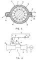
- Fig. 1 is a system diagram schematically showing a gas turbine plant not forming part of the present invention.
- a gas turbine plant 7 includes an air compressor 8, a gas turbine combustor 9, a gas turbine 10, a driven equipment 11 such as a generator, and a fuel section 12.
- an air AR sucked in the air compressor 8 is made high in pressure, and the high pressure air (highly pressurized air) is supplied to the gas turbine combustor 9 together with a fuel F from the fuel section 12.
- a gas turbine driving combustion gas (main flow gas) generated by the gas turbine combustor 9 is supplied to the gas turbine 10, and then, the gas turbine combustion gas is expanded so as to rotate and drive the driven equipment 11 with a rotating torque generated in the expanding process.
- the fuel section 12 includes a fuel tank 13, a fuel pump 14, and a fuel valve 15, and in this structure, the fuel section 12 may be called a fuel supply section or system.
- a heat exchange section (heat exchanger or heat exchanging unit) 16 is provided for the air compressor 8.
- the fuel F from the fuel tank 13 is pressurized by the fuel pump 14, and then, a flow rate of the fuel F is controlled by the fuel valve 15.
- a high pressure air (highly pressurized air) of the air compressor 8 makes heat exchange in the heat exchange section 16 so as to be used as a heating source, and at this time, the fuel F is increased in its quantity of heat (energy) and is supplied to the gas turbine combustor 9.
- a recent air compressor has a pressure ratio of 15 or more, and a high pressure air temperature of 400°C or more corresponding to the pressure ratio. Therefore, the air compressor can be sufficiently used as a heating source with respect to a temperature for heating fuel, that is, about 350 °C .
- the high pressure air of the air compressor 8 is used as a heating source.
- the heating source can be readily obtained, and a flow rate of fuel can be relatively reduced without giving any influence to other constituent equipments as compared with the conventional case, and therefore, a plant heat efficiency can be improved.
- Fig. 2 is a diagram schematically showing a modified embodiment of the heat exchange section 16.
- like reference numerals are used to designate the same components or the corresponding part, and the overlapping explanation is omitted.
- the heat exchange section 16 is provided at a casing 17 of the air compressor 8.
- the heat exchange section 16 is constructed in the following manner. More specifically, as shown in Fig. 3, an outer cover 18 is formed concentrically with the casing 17 of the air compressor 8 so as to form a fuel passage 19, and one side of the fuel passage 19 is provided with a fuel inlet 22 and a fuel outlet 23. Further, the other side of the fuel passage 19 is provide with a connecting pipe 21, and a high pressure air passing through air compressor stationary blades 24 is used as a heating source so as to heart the fuel F passing through the fuel passage 19.
- a reference numeral 20 denotes a flange
- a reference numeral 25 denotes a rotary shaft (rotor).
- the temperature of high pressure air is high as described above, so that the fuel F can be sufficiently and preferably heated.
- Fig. 4 is a system diagram schematically showing a gas turbine plant not forming part of the present invention. Incidentally, like reference numerals are used to designate the same components or the corresponding parts.
- an air extraction closed (circuit) system 26 is provided at an outlet or a high pressure stage of the air compressor.
- the air extraction closed system 26 includes the heat exchanger section 16, and a high pressure air which has been used for heating the fuel F is recovered to an inlet or a low pressure stage of the air compressor 8.
- the fuel F is heated with the utilization of the air extraction of the air compressor 8, and the extracted air is recovered to the air compressor 8. Therefore, a heating source is effectively used, so that a plant heat (thermal) efficiency can be improved.
- Fig. 5 is a diagram schematically showing a gas turbine plant not forming part of the present invention. Incidentally, like reference numerals are used to designate the same components or the corresponding parts.
- the heat exchange section 16 is provided at an exhaust gas system 27 on an outlet side of the gas turbine 10.
- a gas turbine driving gas (main flow gas) expanded in the gas turbine 10 is discharged into atmosphere.
- the temperature of the exhaust gas (exhaust heat) is about 600°C and is extremely high.
- the high temperature exhaust gas has been taken into consideration.
- the exhaust gas from the gas turbine 10 is used as a heating source, and then, the fuel F from the fuel section 12 is heated in the heat exchange section 16.
- a heat of the exhaust gas from the gas turbine 10 is effectively used, and a quantity of heat of the fuel F is made high, and thus, the fuel flow rate is relatively reduced as compared with the conventional case. Therefore, a plant heat efficiency can be greatly improved as compared with the conventional case.
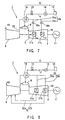
- Fig. 6 is a system diagram schematically showing a gas turbine plant not forming part of the present invention. Incidentally, like reference numerals are used to designate the same components or the corresponding parts.
- the high pressure air when reusing a high pressure air which has been used for heating the fuel F for cooling high temperature sections 31a and 31b of the gas turbine 10, the high pressure air preferably flows depending upon magnitudes of presser losses in these high temperature sections 31a and 31b.
- a high pressure air supply system 29 which is bypassed to a air feed system 28 for supplying a high pressure air from the outlet side of the air compressor 8 to the gas turbine combustor 9.
- the high pressure air supply system 29 is provided at its intermediate portions with the heat exchange section 16 of the fuel section 12 and flow distributing devices 30a and 30b, and the high pressure air supply system 29 is divided into a first high pressure air supply system 29a and a second high pressure air supply system 29b.
- Each of the first and second supply systems 29a and 29b are connected to the high temperature sections 31a and 31b of the gas turbine 10, for example, to gas turbine stationary blades and gas turbine rotating blades, etc.
- a high pressure air recovery system 32 which recovers the overall quantity or a part of the high pressure air which has been used for cooling the high temperature sections 31a and 31b of the gas turbine to the air compressor 8.
- the high pressure air supply system 29 is bypassed from the air feed system 26, it may be provided at an intermediate stage of the air compressor 8.
- two high temperature section 31a and 31b of the gas turbine 10 are shown as an example. Two or more high temperature sections may be provided.
- the flow distributing devices 30a and 30b are constituted specifically as flow control valves or orifices. In the case of using the orifices, a hole diameters of the orifices are set so as to meet with flow rates required for the high temperature sections 31a and 31b.
- the fuel F from the fuel section 12 is heated by the high pressure air from the air compressor 8, and after the fuel F is heated, the high temperature sections 31a and 31b of the gas turbine 10 are cooled by the high pressure air whose temperature becomes low. Further, the overall quantity or part of the high pressure air which has been used for cooling is recovered to the air compressor 8, so that heat can be effectively used. Therefore, a plant heat efficiency is improved, and it is possible to maintain a material strength of the high temperature sections 31a and 31b of the gas turbine 10 while the gas turbine plant 7 being made high temperature.
- Fig. 7 is a system diagram schematically showing a modification of this gas turbine plant. In this case, like reference numerals are used to designate the same components.
- the high pressure air which has been used for cooling the high temperature sections 31a and 31b of the gas turbine 10 is joined together with a gas turbine driving gas G (main flow gas).
- Fig. 8 is a system diagram schematically showing a second modification. In this case, like reference numerals are used to designate the same components.
- the high pressure air recovery system 32 for recovering the high pressure air which has been used for cooling the high temperature sections 31a and 31b of the gas turbine 10 from the first high pressure air supply system 29a and the second high pressure air supply system 29b to the air compressor 8.
- the high pressure air recovery system 32 is divided into a first high pressure air recovery system 32a and a second high pressure air recovery system 32b.
- the first high pressure air recovery system 32a and the second high pressure air recovery system 32b are connected to a relatively high pressure stage of the air compressor 8 and to a relatively low pressure stage of the air compressor 8, respectively.
- the high pressure air is recovered so as to meet with a pressure level of a driving air of the air compressor 8.
- the high pressure air of a proper quantity can be allowed to flow.
- Fig. 9 is a system diagram schematically showing a third modification of the gas turbine plant according to Fig.6.
- like reference numerals are used to designate the same components or the corresponding part.
- a pressure rising compressor 33 is provided in the high pressure air supply system 29 which is divided into the first high pressure air supply system 29a and the second high pressure air supply system 29b.
- the high pressure air from the air compressor 8 is used as a heating source to heat the fuel F, and then, the high pressure air whose temperature becomes low is made high in pressure and is supplied as a cooling medium for cooling the high temperature sections 31a and 31b of the gas turbine 10.
- the high pressure air whose temperature and pressure become low, which has been used for cooling the fuel F is elevated in its pressure by the pressure rising compressor 33, so that the high pressure air can be securely supplied to the high temperature sections 31a and 31b of the gas turbine 10. Therefore, the high temperature sections 31a and 31b of the gas turbine 10 can be securely cooled.
- Fig. 10 is a system diagram schematically showing a fourth modification of the gas turbine plant.
- like reference numerals are used to designate the same components or the corresponding part.
- the pressure rising compressor 33 is provided in the high pressure air supply system 29 which is divided into the first high pressure air supply system 29a and the second high pressure air supply system 29b, and further, there is provided the high pressure air recovery system 32 for recovering the overall quantity or part of high pressure air which has been used for cooling the high temperature sections 31a and 31b of the gas turbine 10 to the air compressor 8.
- the high pressure air recovery system 32 is divided into a first high pressure air recovery system 32a and a second high pressure air recovery system 32b.
- the high pressure air supply system 29 is provided with the pressure rinsing compressor 33, and the fuel F is heated by the heat exchange section 16 of the fuel section 12, and further, the high pressure air whose temperature becomes low is heightened in its pressure, and thus, is supplied to the high temperature sections 31a and 31b of the gas turbine 10 as a cooling medium for cooling them. Then, the overall quantity or part of the high pressure air whose pressure becomes low which has been used for cooling the high temperature sections 31a and 31b of the gas turbine 10, is recovered to the air compressor 8 via the high pressure air recovery system 32 divided into the first high pressure air recovery system 32a and the second high pressure air recovery system 32b. Therefore, a heat of the high pressure air of the air compressor 8 is effectively used, so that a plant heat efficiency can be improved as compared with the conventional case.
- Fig. 11 is a system diagram schematically showing a fifth modification of the gas turbine plant.
- like reference numerals are used to designate the same components as in Fig.6 or the corresponding part.
- the high pressure air supply system 29 is divided into the first high pressure air supply system 29a and the second high pressure air supply system 29b, and these supply systems 29a and 29b are individually provided with a first pressure rising compressor 33a and a second pressure rising compressor 33b. Further, the second high pressure air supply system 29b is bypassed from an outlet side of the first pressure rising compressor 33a.
- These supply systems 29a and 29b are individually provided with the first pressure rising compressor 33a and the seoond pressure rising compressor 33b, and further, the second high pressure air supply system 29b is bypassed from the outlet side of the first pressure rising compressor 33a.
- the fuel F is heated by the heat exchange section 16 of the fuel section 12, and it is possible to securely supply the high pressure air whose temperature becomes low to the high temperature sections 31a and 31b. Therefore, each of the high temperature sections 31a and 31b can be securely cooled.
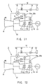
- Fig. 12 is a system diagram schematically showing a sixth modification of the gas turbine plant according to Fig.6.
- like reference numerals are used to designate the same components as in Fig 6 or the corresponding part.
- the high pressure air supply system 29 is divided into the first high pressure air supply system 29a and the second high pressure air supply system 29b which are arranged in parallel.
- the first high pressure air supply system 29a is provided with the first pressure rising compressor 33a
- the second high pressure air supply system 29b is provided with the second pressure rising compressor 33b.
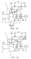
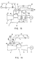
- Fig. 13 is a system diagram schematically showing a seventh modification of the gas turbine plant according to Fig.6.
- like reference numerals are used to designate the same components as in Fig 6 or the corresponding part.
- the high pressure air supply system 29 is divided into the first high pressure air supply system 29a and the second high pressure air supply system 29b which are arranged in parallel, and only the first high pressure air supply system 29a is provided with the pressure rising compressor 33.
- the high pressure air recovery system 32 for recovering the overall quantity or part of the high pressure air which has been used for cooling the high temperature sections 31a and 31b of the gas turbine 10 to the air compressor 8. Then, the high pressure air recovery system 32 is divided into the first high pressure air recovery system 32a and the second high pressure air recovery system 32b.
- the first high pressure air recovery system 32a and the second high pressure air recovery system 32b are Connected to a high pressure stage side of the air compressor 8 and to a low pressure stage side of the air compressor 8, respectively.
- the fuel F is heated by the heat exchange section 16 of the fuel section, and the high pressure air whose temperature becomes low can be securely supplier to the high temperature sections 31a and 31b of the gas turbine 10. Further, when recovering the overall quantity or part of the high pressure air which has been used for cooling the high temperature sections 31a and 31b of the gas turbine 10, the high pressure air can be preferably recovered without giving a fluctuation to a driving air of the air compressor 8.
- Fig. 14 is a system diagram schematically showing an eighth modification of the gas turbine plant according to Fig 6, forming an embodiment of the present invention.
- like reference numerals are used to designate the same components as in Fig 6 or the corresponding part.
- the high pressure air supply system 29 is divided into the first high pressure air supply system 29a and the second high pressure air supply system 29b, and the pressure rising compressor 33 is provided so as to correspond to the inlets of the divided first high pressure air supply system 29a and second high pressure air supply system 29b.
- the high pressure air recovery system 32 for recovering the overall quantity or part of the high pressure air from the first high pressure air supply system 29a which has been used for cooling the high temperature section 31a on a relatively high pressure stage side of the gas turbine 10 to the outlet side of the air compressor 8, and a cooling recovery system 24 for recovering the overall quantity or part of the high pressure air from the second high pressure air supply system 29b which has been used for cooling the high temperature section 31b on a relatively low pressure stage side of the gas turbine 10, to the inlet side of the heat exchange section 16 of the fuel section 12.
- the high pressure air supply system 29 is provided with the pressure rising compressor 33, and the outlet side of the pressure rising compressor 33 is divided into the first high pressure air supply system 29a and the second high pressure air supply system 29b. Further, the fuel F is heated by the heat exchange section 16 of the fuel section 12, and then, the high pressure air whose temperature becomes low is elevated in its pressure by the pressure rising compressor 33, and thus, is supplied to the high temperature sections 31a and 31b of the gas turbine 10 via the respective high pressure air supply systems 29a and 29b.
- the overall quantity or part of the high pressure air which has been used for cooling the high temperature sections 31a and 31b of the gas turbine 10 is recovered to the air compressor 8 via the high pressure air recovery system 32, and then, the overall quantity or part of the high pressure air after cooling them is recovered to the inlet side of the heat exchange section 16 via the cooling recovery system 34. Therefore, a heat is effectively used, so that a plant heat efficiency can be greatly improved more than conventional case.
- Fig. 15 is a system diagram schematically showing a gas turbine plant not forming part of the present invention.
- like reference numerals are used to designate the same components or the corresponding part.
- the high pressure air supply system 29 which is constructed in such a manner that an air supply system 28 for supplying the high pressure air from the air compressor 8 to the gas turbine combustor 9, is bypassed thereto.
- the high pressure air supply system 29 is provided with the heat exchange section 16 of the fuel section 12, and a heat utilizing device 36, for example, a heat exchange section 37 for co-generation heat recovery device.
- the high pressure air supply system 29 is further provided with flow distributing devices 30a and 30b so as to be divided into the first high pressure air supply system 29a and the second high pressure air supply system 29b.
- the divided first and second high pressure air supply systems 29a and 29b are connected to the high temperature sections 31a and 31b of the gas turbine 10, respectively.
- a medium to be heated from the heat utilizing device 36 for example, a cooling water
- a medium to be heated from the heat utilizing device 36 is heated by the heat exchange section 37 for heat utilizing device, and further, cools the high temperature sections 31a and 31b of the gas turbine 10 via the flow distributing devices 30a and 30b of the first and second high pressure air supply systems 29a and 29b, and thereafter, is recovered from the high temperature sections 31a and 31b to the air compressor 8 via the high pressure air recovery system 32.
- the heat of the high pressure air can be effectively used for multi-purpose.
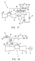
- Fig. 16 is a system diagram schematically showing a gas turbine plant not forming part of the present invention.
- like reference numerals are used to designate the same components or the corresponding part.
- an air extraction closed system 35 is provided on a high pressure stage side of the air compressor 8.
- the air extraction closed system 35 is provided with the heat exchange section 16 of the fuel section 12, and the heat utilizing device 36, for example, the heat exchange section 37 for co-generation heat utilizing device.
- the high pressure air from the air compressor 8 is used as a heating source so that the fuel F from the fuel section is heated in the heat exchange section 16.
- a medium to be heated from the heat utilizing device 36 for example, a cooling water CW, is heated in the heat exchange section 37 for the heat utilizing device, and then, the high pressure air is recovered to the air compressor 8.
- the air compressor 8 is provided with the air extraction closed system 35, and the air extraction closed system 35 is provided with the heat exchange section 16 of the fuel section 12, the heat utilizing device 36 and the heat exchange section 37 for the heat utilizing device. Further, the high pressure air extracted from the air compressor 8 is used as a heating source so that the fuel F from the fuel section 12 is heated in the heat exchange section 16, and then, a medium to be heated from the heat utilizing device 36 is heated in the heat exchange section 37 for heat utilizing device. Therefore, the heat of high pressure air can be effectively used for multi-purpose.
- Fig. 17 is a system diagram schematically showing a gas turbine plant not forming part of the present invention.
- like reference numerals are used to designate the same components as the first embodiment or the corresponding part.
- the gas turbine plant 7 is combined with a steam turbine plant 38, and an exhaust gas system 39 of the gas turbine 10 is provided with a first exhaust heat recovery heat exchanger 44 and a second exhaust heat recovery heat exchanger 43 of the steam turbine plant 38, and the heat exchange section 16 of the fuel section 12.
- the steam turbine plant 38 is a so-called single-shaft type which is constructed in such a manner that the gas turbine 10 is connected in shaft directly to a steam turbine 40 via a driven equipment 11, for example, a generator. Further, the steam turbine plant 38 is formed as a closed circuit system including a condenser 41, a pump 42, the second exhaust heat recovery heat exchanger 43 and the first exhaust heat recovery heat exchanger 44. A feed water supplied from the pump 42 is heated (preheated) by the second exhaust heat recovery heat exchanger 43 with the use of an exhaust gas (exhaust heat) discharged from the exhaust gas system 39 of the gas turbine 10 to atmospheric air as a heating source.
- the heated water is heated by the first exhaust heat recovery heat exchanger 44 using the exhaust gas of the heat exchanger 43 as a heating source, and thereby, the heated water is made into a steam, and the steam is supplied to the steam turbine 40, and thus, a power is generated.
- the heat exchanger section 16 has been disposed between the first exhaust heat recovery heat exchanger 44 and the second exhaust heat recovery heat exchanger 43, as an example.
- the heat exchanger section 16 may be disposed on an upstream side of the first exhaust heat recovery heat exchanger 44 or may be disposed on a downstream side of the second exhaust heat recovery heat exchanger 43.
- the exhaust gas system 39 of the gas turbine 10 is provided with the first exhaust heat recovery heat exchanger 44 and the second exhaust heat recovery heat exchanger 43 of the steam turbine plant 38 and the heat exchange section 16 of the fuel section 12 so as to generate a steam and heat the fuel F, and the heat of exhaust gas is sufficiently used. Therefore, a plant heat efficiency can be greatly improved by a small quantity of fuel as compared with the conventional case.
- Fig. 18 is a system diagram schematically showing a gas turbine plant not forming part of the present invention.
- like reference numerals are used to designate the same components or the corresponding part.
- the heat exchange section 16 is provided with a fuel leak detector 45, a valve opening control section 46, an alarm device 47 and a fuel leak display device (indicator) 48.
- the valve opening control section 46 is constructed so as to close a fuel valve 15 if a fuel leak signal detected by the fuel leak detector 45 exceeds a predetermined value.
- the alarm device 47 also gives the alarm if a fuel leak signal detected by the fuel leak detector 45 exceeds a predetermined value.
- the fuel leak display 48 displays a leaked fuel concentration detected by the fuel leak detector 45 so that a worker can visibly confirm the fuel leakage.
- the gas turbine combustor 9 can be safely operated without operating the gas turbine combustor 9 in a state that the fuel leaks.
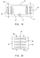
- Fig. 19 is a view schematically showing a first modified embodiment of the heat exchange section 16 in the gas turbine plant according to the present invention.
- a fuel flows through a heat-transfer pipe, and a heating medium flows outside the heat-transfer pipe.
- a fuel leakage from the heat-transfer pipe is taken into consideration.
- the heat exchange section 16 is divided into a first heat exchange section 49 and a second heat exchange section 50.
- a high temperature heating medium HG flows through the first heat exchange section 49 while an intermediate heating medium IG, for example, an inert gas such as nitrogen gas or the like being supplied to the second heat exchange section 50 so that the fuel F is heated.
- the intermediate heating medium IG heated the fuel F is circulated into the first heat exchange section 49 via a pump 51.
- the heat exchange section 16 of this embodiment isdivided into the first heat exchange section 49 and the second heat exchange section 50, and the fuel F is heated by the intermediate heating medium IG.
- the heat exchange section 16 of this embodiment isdivided into the first heat exchange section 49 and the second heat exchange section 50, and the fuel F is heated by the intermediate heating medium IG.
- Fig. 20 is a view schematically showing a second modified embodiment of the heat exchange section 16 in the gas turbine plant according to the present invention.
- the heat exchange section 16 of this embodiment is divided into a high temperature chamber 52 and a low temperature chamber 53 and is attached with a heat pipe 54 in a manner of crossing these chambers 52 and 53.
- the high temperature heating medium HG supplied to the high temperature chamber 52 heats the heat pipe 54, and then, the heat is transferred to the fuel F of the low temperature chamber 53 so as to heat the fuel F.
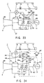
- Fig. 21 is a system diagram schematically showing a gas turbine plant not forming part of the present invention.
- like reference numerals are used to designate the same components or the corresponding part.
- the high pressure air discharged from the air compressor 8 via a discharged air system is used as a heating source for heating the fuel F of the fuel section 12.
- a check valve 56 and the heat exchange section 16 of the fuel section 12 are bypassed from the midway of the discharged air system 55, and thus, there is provided a discharged air recovery system 57 connected to a low pressure state of the air compressor 8 or to an outlet thereof.
- the discharged air system 55 includes a discharged air valve 58.
- the discharged air valve 58 includes a valve opening control section 59.
- the valve opening is computed (operated) by the valve opening control section 59 on the basis of at least one or more signals of a rotational speed signal from a rotational speed detector 61 which detects a rotational speed of a gas turbine shaft 60 and an operating signal from a power detector 62 which detects a power of the driven equipment 11. In this manner, a control for opening and closing the valve is made on the basis of the operational signal.
- a flow rate of the high pressure air discharged from the air compressor 8 to the atmospheric air via the discharged air system 55 is controlled by the discharged air valve 58, and then, the high pressure air thus controlled in the flow rate is used as a heating source so that the fuel F of the fuel section 12 is heated in the heat exchange section 16 provided in the discharge air recovery system 57, and thus, is recovered to the air compressor 8. Therefore, the heat is effectively used, so that a plant heat efficiency can be improved as compared with the conventional case.
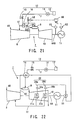
- Fig. 22 is a system diagram schematically showing a gas turbine plant not forming part of the present invention.
- like reference numerals are used to designate the same components or the corresponding part.
- the following matter is taken into consideration. More specifically, in the case where an accident happens in a driving source of the pressure rising compressor 33 provided in the high pressure air supply system 29 divided into the first high pressure air supply system 29a and the second high pressure air supply system 29b, and then, the pressure rising compressor 33 is not operated, the high pressure air from the air compressor 8 is not supplied to the high temperature sections 31a and 31b of the gas turbine 10 in order to cool these high temperature sections. Thus, the pressure rising compressor 33 is connected directly to the gas turbine shaft 60.
- the pressure rising compressor 33 is connected directly to the gas turbine shaft 60.
- the fuel F from the fuel section 12 is heated in the heat exchange section 16 using the high pressure air from the air compressor 8, and the high pressure air whose temperature becomes low is securely supplied to the high temperature sections 31a and 31b of the gas turbine 10 via the flow distributing devices 30a and 30b as a cooling medium for cooling these high temperature sections. Therefore, the gas turbine 10 can be safely operated.
- Fig. 23 is a system diagram schematically showing a modification of the gas turbine plant according to Fig. 22.
- like reference numerals are used to designate the same components as in Fig. 22 or the corresponding part.
- the pressure rising compressor 33 is provided in the high pressure air supply system 29 divided into the first high pressure air supply system 29a and the second high pressure air supply system 29b, and the pressure rising compressor 33 is connected to the gas turbine shaft 60 via a power transmission mechanism section 63. Either one of gear or torque converter is selected as the power transmission mechanism section 63.
- the pressure rising compressor 33 supplies the high temperature air from the air compressor 8 heating the fuel F in the heat exchange section 16 of the fuel section 12 to the high temperature sections 31a and 31b of the gas turbine as a cooling medium for cooling these high temperature sections.
- the pressure rising compressor 33 is connected to the gas turbine shaft 60 via the power transmission mechanism section 63 so as to be driven by a rotating torque of the gas turbine shaft 60. Therefore, the pressure rising compressor 33 can be securely driven.
- Fig. 24 is a system diagram schematically showing a gas turbine plant not forming part of the present invention.
- like reference numerals are used to designate the same components or the corresponding part.
- the high pressure air extracted from the intermediate stage of the air compressor 8 is supplied to the heat exchange section 16 of the fuel section 12 via the high pressure air supply system 29 so as to heat the fuel F, and then, the high pressure air whose temperature becomes low is supplied to the high temperature sections 31a and 31b of the gas turbine 10 as a cooling medium for cooling these high temperature sections via the pressure rising compressor 33, the check valve 64, the flow distributing devices 30a and 30b.
- the high pressure air of a proper quantity is not supplied to the high temperature sections 31a and 31b of the gas turbine 10 in accordance with various operating conditions, these high temperature sections 31a and 31b are burnt.
- a re-circulation system 65 is provided between the outlet side of the pressure rising compressor 33 and the inlet side of the check valve 64 so that a part of the high pressure air can be circulated.
- a bypass is made between the outlet side of the pressure rising compressor 33 and the inlet side of the check valve 64, and there is provided a re-circulation valve 66 so that the re-circulation system 65 is connected to the inlet side of the heat exchange section 16.
- the re-circulation valve 66 includes a valve opening control section 67.
- the valve opening control section 67 calculates a pressure ratio of the pressure rising compressor 33 in response to a pressure signal from pressure instruments 68a and 68b provided on each of inlet and outlet sides of the pressure rising compressor 33, a temperature signal from a thermometer 69 provided on the high pressure air recovery system 32, a rotational speed signal from the rotational speed detector 61 provided on the gas turbine shaft 60, and a power signal from the power detector 62 provided on the driven equipment 11.
- valve opening control section 67 computes the valve opening signal so that the pressure ratio becomes a specified value determined by at least one of the rotational speed of the gas turbine shaft 60, the power signal of the driven equipment 11, and a high pressure air signal of the high pressure air recovery system 32, and then, supplies the operational signal to the re-circulation valve 66, and thus, performs a control for opening and closing the re-circulation valve.
- a part of the high pressure air of the high pressure air supply system 29 is circulated via the re-circulation system 65, and thus, the pressure ratio of the pressure rising compressor 33 is kept at a proper value, so that the high temperature sections 31a and 31b of the gas turbine 10 can be securely cooled.
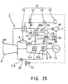
- Fig. 25 is a system diagram schematically showing a first modification of the gas turbine plant according to Fig. 24.
- like reference numerals are used to designate the same components or the corresponding part.
- the high pressure air extracted from the intermediate stage of the air compressor 8 is supplied to the heat exchange section 16 of the fuel section 12 via the high pressure air supply system 29 so as to heat the fuel F, and then, the high pressure air whose temperature becomes low is supplied to the high temperature sections 31a and 31b of the gas turbine 10 as a cooling medium for cooling these high temperature sections via the pressure rising compressor 33, and the flow distributing devices 30a and 30b.
- the pressure rising compressor 33 or a drive equipment 70 for pressure rising compressor is not operated due to any reasons.
- the pressure rising compressor 33 is provided with a pressure rising compressor bypass system 72 including a check valve 71, and a discharge valve 73 is provided on an inlet side of a high pressure air recovery check valve 71a of the high pressure air recovery system 32.
- a pressure rising compressor bypass system 72 including a check valve 71 and a discharge valve 73 is provided on an inlet side of a high pressure air recovery check valve 71a of the high pressure air recovery system 32.
- the valve opening control section 67 computes a valve opening signals on the basis of the pressure signal from the pressure instruments 68a and 68b and the rotational speed signal from a pressure rising compressor rotational speed (frequency) detector 74, and then, transmits the operational signal to the discharge valve 73 and the fuel valve 15 of the fuel section 12 so that the discharge valve 73 is opened while the fuel valve 15 being closed.
- the air compressor 8 supplies the residual high pressure air to the high temperature sections 31a and 31b of the gas turbine 10 via the high pressure air supply system 29, the check valve 71 and the pressure rising compressor bypass system 72 so as to cool these high temperature sections 31a and 31b.
- the residual high pressure air is discharged from the discharge valve 73 to the atmospheric air via the high pressure air recovery system 32.
- the discharge valve 73 when the discharge valve 73 is fully opened, the pressure of the high pressure air passing through the high temperature sections 31a and 31b of the gas turbine 10 lowers.
- the high pressure air recovery check valve 71a is provided on the downstream side of the discharge valve 73, and therefore, the residual high pressure air from the air compressor 8 does not conversely flow into the discharge valve 73.
- the high pressure air remaining in the air compressor 8 is supplied to the high temperature sections 31a and 31b of the gas turbine 10 via the high pressure sir supply system 29, the check valve 71 and the pressure rising compressor bypass system 72 so that these high temperature sections 31a and 31b are continuously cooled.
- the check valve 71 and the pressure rising compressor bypass system 72 so that these high temperature sections 31a and 31b are continuously cooled.
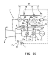
- Fig. 26 is a system diagram schematically showing a second modification of the gas turbine plant according to Fig. 24.
- like reference numerals are used to designate the same components or the corresponding part.
- the high pressure air extracted from the intermediate stage of the air compressor 8 is supplied to the heat exchange section 16 of the fuel section 12 via the high pressure air supply system 29 so as to heat the fuel F, and then, the high pressure air whose temperature becomes low is supplied to the high temperature sections 31a and 31b of the gas turbine 10 as a cooling medium for cooling these high temperature sections via the pressure rising compressor 33, the check valve 64 and the flow distributing devices 30a and 30b.
- the pressure rising compressor 33 or the drive equipment 70 for pressure rising compressor is not operated due to any reasons.
- a flow control valve 75 and an accumulator 76 are provided on the outlet side of the check valve 64.
- the high temperature sections 31a and 31b of the gas turbine 10 are continuously cooled by an accumulated (stored) air of the accumulator 76 until the gas turbine plant 7 is stopped.
- valve opening control section 67 computes a valve opening signal on the basis of the pressure signal from the pressure instruments 68a and 68b and the rotational speed signal from a pressure rising compressor rotational speed detector 74, and then, transmits the operational signal to the discharge valve 73 provided on the inlet side of the high pressure air recovery check valve 71a of the high pressure air recovery system 32, the fuel valve 15 of the fuel section 12 and the flow control valve 75 so that the fuel valve 15 is closed while the discharge valve 73 and the flow control valve 75 being opened.
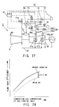
- Fig. 27 is a system diagram schematically showing a third modification of the gas turbine plant not forming part of the present invention.
- like reference numerals are used to designate the same components or the corresponding part.
- discharge valves 77a and 77b are provided on the high pressure air supply system 29 on the inlet side of the heat exchange section 16 and the high pressure air supply system 29 on the outlet side of the pressure rising compressor 33, respectively. If an accident happens in the pressure rising compressor 33 or the drive equipment 70 for pressure rising compressor, according to the operational signal from the valve opening control section 67, the fuel valve 15 of the fuel section 12 is closed while the discharge valves 77a and 77b being opened, and then, the high pressure air of the high pressure air supply system 29 is discharged to the atmospheric air via these discharge valves 77a and 77b.
- the high pressure air remaining in the air compressor 8 conversely flows into the high temperature sections 31a and 31b of the gas turbine 10 via the high pressure air recovery system 32 so that the high temperature sections 31a and 31b of the gas turbine 10 are cooled, and thereafter, is discharged to the atmospheric air via the discharge valve 77b.
- the discharge valves 77a and 77b are opened so that the high pressure air of the high pressure air supply system is discharged to the atmospheric air, and during this discharge, the high pressure air remaining in the air compressor 8 conversely flows into the high temperature sections 31a and 31b of the gas turbine 10 via the high pressure air supply system so as to cool these high temperature sections 31a and 31b.
- the high pressure air remaining in the air compressor 8 conversely flows into the high temperature sections 31a and 31b of the gas turbine 10 via the high pressure air supply system so as to cool these high temperature sections 31a and 31b.
- Fig. 28 is a graph showing a comparison in a plant heat (thermal) efficiency between a gas turbine plant according to each embodiment of the present invention and the prior art.
- the high pressure air of the air compressor 8 is used as a heating source, and the fuel F supplied from the fuel section 12 to the gas turbine combustor 9 is heated by the heat exchange section 16, and thus, the quantity of heat (energy) of the fuel F is enhanced. By doing so, it is possible to improve a plant heat efficiency by consumption of a small fuel F.
- the gas turbine plant according to each embodiment of the present invention and the prior art makes it possible to relatively reduce the consumption of the fuel F as compared with the prior art. Therefore, the plant heat efficiency can be improved about 0.5 to 1.0% as compared with the prior art.
Landscapes
- Engineering & Computer Science (AREA)
- Chemical & Material Sciences (AREA)
- Combustion & Propulsion (AREA)
- Mechanical Engineering (AREA)
- General Engineering & Computer Science (AREA)
- Engine Equipment That Uses Special Cycles (AREA)
- Air Supply (AREA)
Priority Applications (2)
| Application Number | Priority Date | Filing Date | Title |
|---|---|---|---|
| EP03024525A EP1394390B1 (en) | 1997-09-18 | 1998-09-17 | Gas turbine plant |
| EP03024524A EP1391596B1 (en) | 1997-09-18 | 1998-09-17 | Gas turbine plant |
Applications Claiming Priority (3)
| Application Number | Priority Date | Filing Date | Title |
|---|---|---|---|
| JP25380197 | 1997-09-18 | ||
| JP9253801A JPH1193694A (ja) | 1997-09-18 | 1997-09-18 | ガスタービンプラント |
| JP253801/97 | 1997-09-18 |
Related Child Applications (2)
| Application Number | Title | Priority Date | Filing Date |
|---|---|---|---|
| EP03024524A Division EP1391596B1 (en) | 1997-09-18 | 1998-09-17 | Gas turbine plant |
| EP03024525A Division EP1394390B1 (en) | 1997-09-18 | 1998-09-17 | Gas turbine plant |
Publications (3)
| Publication Number | Publication Date |
|---|---|
| EP0903484A2 EP0903484A2 (en) | 1999-03-24 |
| EP0903484A3 EP0903484A3 (en) | 2000-11-02 |
| EP0903484B1 true EP0903484B1 (en) | 2005-04-27 |
Family
ID=17256349
Family Applications (3)
| Application Number | Title | Priority Date | Filing Date |
|---|---|---|---|
| EP98117671A Expired - Lifetime EP0903484B1 (en) | 1997-09-18 | 1998-09-17 | Gas turbine plant with fuel preheater |
| EP03024525A Expired - Lifetime EP1394390B1 (en) | 1997-09-18 | 1998-09-17 | Gas turbine plant |
| EP03024524A Expired - Lifetime EP1391596B1 (en) | 1997-09-18 | 1998-09-17 | Gas turbine plant |
Family Applications After (2)
| Application Number | Title | Priority Date | Filing Date |
|---|---|---|---|
| EP03024525A Expired - Lifetime EP1394390B1 (en) | 1997-09-18 | 1998-09-17 | Gas turbine plant |
| EP03024524A Expired - Lifetime EP1391596B1 (en) | 1997-09-18 | 1998-09-17 | Gas turbine plant |
Country Status (8)
| Country | Link |
|---|---|
| US (7) | US6253554B1 (zh) |
| EP (3) | EP0903484B1 (zh) |
| JP (1) | JPH1193694A (zh) |
| KR (1) | KR100313824B1 (zh) |
| CN (3) | CN1183318C (zh) |
| AU (1) | AU8523098A (zh) |
| DE (3) | DE69829925T2 (zh) |
| ID (1) | ID20875A (zh) |
Cited By (1)
| Publication number | Priority date | Publication date | Assignee | Title |
|---|---|---|---|---|
| US11846237B2 (en) | 2017-01-19 | 2023-12-19 | Rtx Corporation | Gas turbine engine with intercooled cooling air and dual towershaft accessory gearbox |
Families Citing this family (139)
| Publication number | Priority date | Publication date | Assignee | Title |
|---|---|---|---|---|
| DE19824766C2 (de) * | 1998-06-03 | 2000-05-11 | Siemens Ag | Gasturbine sowie Verfahren zur Kühlung einer Turbinenstufe |
| US6578362B1 (en) | 1999-05-17 | 2003-06-17 | General Electric Co. | Methods and apparatus for supplying cooling air to turbine engines |
| DE60033738T2 (de) * | 1999-07-01 | 2007-11-08 | General Electric Co. | Vorrichtung zur Befeuchtung und Heizung von Brenngas |
| WO2001034956A1 (en) * | 1999-11-10 | 2001-05-17 | Hitachi, Ltd. | Gas turbine equipment and gas turbine cooling method |
| DE10009655C1 (de) * | 2000-02-29 | 2001-05-23 | Mtu Aero Engines Gmbh | Kühlluftsystem |
| US6584778B1 (en) | 2000-05-11 | 2003-07-01 | General Electric Co. | Methods and apparatus for supplying cooling air to turbine engines |
| DE10027842A1 (de) * | 2000-06-05 | 2001-12-20 | Alstom Power Nv | Verfahren zum Kühlen einer Gasturbinenanlage sowie Gasturbinenanlage zur Durchführung des Verfahrens |
| DE10027833A1 (de) * | 2000-06-05 | 2001-12-13 | Alstom Power Nv | Verfahren zum Kühlen einer Gasturbinenanlage sowie Gasturbinenanlage zur Durchführung des Verfahrens |
| US6523346B1 (en) * | 2001-11-02 | 2003-02-25 | Alstom (Switzerland) Ltd | Process for controlling the cooling air mass flow of a gas turbine set |
| EP1525380A1 (de) * | 2002-07-25 | 2005-04-27 | Siemens Aktiengesellschaft | Kühlsystem zur kühlung von kühlluft einer gasturbine und verfahren zur kühlung von kühlluft |
| EP1389668A1 (de) * | 2002-08-16 | 2004-02-18 | Siemens Aktiengesellschaft | Gasturbine |
| US7185483B2 (en) | 2003-01-21 | 2007-03-06 | General Electric Company | Methods and apparatus for exchanging heat |
| WO2005041396A2 (en) * | 2003-10-22 | 2005-05-06 | Scherzer Paul L | Method and system for generating electricity utilizing naturally occurring gas |
| GB2409001B (en) * | 2003-12-13 | 2006-04-05 | Rolls Royce Plc | Transferring thermal energy between gas and a fuel in a gas turbine engine |
| US20050137441A1 (en) * | 2003-12-18 | 2005-06-23 | Harry Cordatos | Multi-stage fuel deoxygenator |
| US7231769B2 (en) * | 2004-01-29 | 2007-06-19 | United Technologies Corporation | Gas turbine cooling system |
| US7744827B2 (en) * | 2004-02-13 | 2010-06-29 | United Technologies Corporation | Catalytic treatment of fuel to impart coking resistance |
| US7334407B2 (en) * | 2004-03-22 | 2008-02-26 | United Technologies Corporation | Method of suppressing coke in endothermic fuel processing |
| US7153343B2 (en) * | 2004-03-24 | 2006-12-26 | United Technologies Corporation | Fuel deoxygenation system |
| US20050274649A1 (en) * | 2004-06-09 | 2005-12-15 | Spadaccini Louis J | Method for suppressing oxidative coke formation in liquid hydrocarbons containing metal |
| US7487642B2 (en) * | 2005-11-01 | 2009-02-10 | General Electric Comapny | Methods and apparatus for operating gas turbine engines |
| US7640751B2 (en) * | 2006-05-25 | 2010-01-05 | Siemens Energy, Inc. | Fuel heating system for turbine engines |
| GB0610357D0 (en) | 2006-05-25 | 2006-07-05 | Rolls Royce Plc | Loss reduction apparatus |
| JP2008082247A (ja) * | 2006-09-27 | 2008-04-10 | Mitsubishi Heavy Ind Ltd | ガスタービン |
| US7861509B2 (en) * | 2007-01-23 | 2011-01-04 | General Electric Company | Methods and systems for gas turbine syngas warm-up with low emissions |
| FR2914365B1 (fr) * | 2007-03-28 | 2012-05-18 | Airbus France | Systeme de refroidissement et de regulation en temperature d'equipements d'un ensemble propulsif d'aeronef. |
| EP1975388A1 (en) * | 2007-03-28 | 2008-10-01 | Siemens Aktiengesellschaft | Gas turbine engine with fuel booster |
| US7954324B2 (en) * | 2007-04-05 | 2011-06-07 | Siemens Energy, Inc. | Gas turbine engine |
| US7992549B2 (en) * | 2007-05-21 | 2011-08-09 | Casey Loyd | Method of fueling an internal combustion engine using pressurized and heated fuel |
| US8127547B2 (en) * | 2007-06-07 | 2012-03-06 | United Technologies Corporation | Gas turbine engine with air and fuel cooling system |
| US20090051167A1 (en) * | 2007-08-22 | 2009-02-26 | General Electric Company | Combustion turbine cooling media supply method |
| US20090056342A1 (en) * | 2007-09-04 | 2009-03-05 | General Electric Company | Methods and Systems for Gas Turbine Part-Load Operating Conditions |
| US8220268B2 (en) * | 2007-11-28 | 2012-07-17 | Caterpillar Inc. | Turbine engine having fuel-cooled air intercooling |
| EP2260193B1 (de) * | 2008-03-05 | 2018-08-29 | Ansaldo Energia IP UK Limited | Verfahren zur regelung einer gasturbine in einem kraftwerk und kraftwerk zur durchführung des verfahrens |
| US8277170B2 (en) * | 2008-05-16 | 2012-10-02 | General Electric Company | Cooling circuit for use in turbine bucket cooling |
| US8596073B2 (en) * | 2008-07-18 | 2013-12-03 | General Electric Company | Heat pipe for removing thermal energy from exhaust gas |
| US8186152B2 (en) * | 2008-07-23 | 2012-05-29 | General Electric Company | Apparatus and method for cooling turbomachine exhaust gas |
| US8015790B2 (en) * | 2008-07-29 | 2011-09-13 | General Electric Company | Apparatus and method employing heat pipe for start-up of power plant |
| US8425223B2 (en) * | 2008-07-29 | 2013-04-23 | General Electric Company | Apparatus, system and method for heating fuel gas using gas turbine exhaust |
| US20100024424A1 (en) * | 2008-07-29 | 2010-02-04 | General Electric Company | Condenser for a combined cycle power plant |
| US8359824B2 (en) * | 2008-07-29 | 2013-01-29 | General Electric Company | Heat recovery steam generator for a combined cycle power plant |
| US8157512B2 (en) * | 2008-07-29 | 2012-04-17 | General Electric Company | Heat pipe intercooler for a turbomachine |
| US20100043442A1 (en) * | 2008-08-19 | 2010-02-25 | General Electric Company | Dimpled serrated fintube structure |
| EP2159399A1 (de) * | 2008-08-27 | 2010-03-03 | Siemens Aktiengesellschaft | Verfahren zum Vorwärmen eines in einer Gasturbine zu verbrennenden Brennstoffs und Gasturbine mit einem Brennstoff-Leitungssystem |
| US20100064655A1 (en) * | 2008-09-16 | 2010-03-18 | General Electric Company | System and method for managing turbine exhaust gas temperature |
| JP5185762B2 (ja) * | 2008-10-08 | 2013-04-17 | 三菱重工業株式会社 | ガスタービン及びその起動時運転方法 |
| JP5185763B2 (ja) * | 2008-10-08 | 2013-04-17 | 三菱重工業株式会社 | ガスタービン及びその停止時運転方法 |
| EP2708720B1 (en) | 2008-10-08 | 2018-02-21 | Mitsubishi Heavy Industries, Ltd. | Gas turbine and operating method thereof |
| JP5496486B2 (ja) * | 2008-10-08 | 2014-05-21 | 三菱重工業株式会社 | ガスタービン及びその定格時運転方法 |
| US20100095648A1 (en) * | 2008-10-17 | 2010-04-22 | General Electric Company | Combined Cycle Power Plant |
| CN101737794B (zh) * | 2008-11-21 | 2011-10-19 | 中国神华能源股份有限公司 | 一种性能加热器控制优化方法 |
| US8172521B2 (en) * | 2009-01-15 | 2012-05-08 | General Electric Company | Compressor clearance control system using turbine exhaust |
| US8778063B2 (en) | 2009-02-04 | 2014-07-15 | Purdue Research Foundation | Coiled and microchannel heat exchangers for metal hydride storage systems |
| KR20110125231A (ko) | 2009-02-04 | 2011-11-18 | 퍼듀 리서치 파운데이션 | 금속 수소화물 저장 시스템용 핀 열교환기 |
| US8117821B2 (en) * | 2009-02-11 | 2012-02-21 | General Electric Company | Optimization of low-BTU fuel-fired combined-cycle power plant by performance heating |
| US8112998B2 (en) * | 2009-04-17 | 2012-02-14 | General Electric Company | Apparatus and method for cooling a turbine using heat pipes |
| US20100281870A1 (en) * | 2009-05-08 | 2010-11-11 | General Electric Company | System and method for heating fuel for a gas turbine |
| US20100319359A1 (en) * | 2009-06-19 | 2010-12-23 | General Electric Company | System and method for heating turbine fuel in a simple cycle plant |
| IL199803A (en) | 2009-07-12 | 2012-07-31 | Lv Technologies Ltd | Method and system for enhancing engine performance |
| US20110232298A1 (en) * | 2010-03-23 | 2011-09-29 | General Electric Company | System and method for cooling gas turbine components |
| US9279340B2 (en) | 2010-03-23 | 2016-03-08 | General Electric Company | System and method for cooling gas turbine components |
| CN102822475B (zh) | 2010-04-01 | 2015-06-17 | 阿尔斯通技术有限公司 | 用于提高配备有燃气涡轮的发电设备的效率的方法以及用于执行该方法的发电设备 |
| US8141367B2 (en) | 2010-05-19 | 2012-03-27 | General Electric Company | System and methods for pre-heating fuel in a power plant |
| US8881530B2 (en) | 2010-09-02 | 2014-11-11 | General Electric Company | Fuel heating system for startup of a combustion system |
| US8186169B2 (en) | 2010-10-22 | 2012-05-29 | General Electric Company | Nitrogen cooled gas turbine with combustor nitrogen injection and partial nitrogen recycling |
| CH704381A1 (de) * | 2011-01-24 | 2012-07-31 | Alstom Technology Ltd | Verfahren zum Betrieb eines Gasturbinenkraftwerks mit Abgasrezirkulation sowie Gasturbinenkraftwerk mit Abgasrezirkulation. |
| US8943827B2 (en) | 2011-05-31 | 2015-02-03 | Pratt & Whitney Canada Corp. | Fuel air heat exchanger |
| WO2013147953A1 (en) * | 2011-12-30 | 2013-10-03 | Rolls-Royce North American Technologies Inc. | Aircraft propulsion gas turbine engine with heat exchange |
| US9580185B2 (en) | 2012-01-20 | 2017-02-28 | Hamilton Sundstrand Corporation | Small engine cooled cooling air system |
| US9541008B2 (en) | 2012-02-06 | 2017-01-10 | General Electric Company | Method and apparatus to control part-load performance of a turbine |
| US8725384B2 (en) | 2012-02-10 | 2014-05-13 | General Electic Company | Detection system and method to detect flame holding event |
| JP2013199925A (ja) * | 2012-02-21 | 2013-10-03 | Mitsubishi Heavy Ind Ltd | ガスタービン設備 |
| US9109842B2 (en) | 2012-02-24 | 2015-08-18 | Pratt & Whitney Canada Corp. | Fuel air heat exchanger |
| US9222415B2 (en) * | 2012-03-06 | 2015-12-29 | Hamilton Sundstrand Corporation | Gas turbine engine fuel heating system |
| US20130239542A1 (en) * | 2012-03-16 | 2013-09-19 | United Technologies Corporation | Structures and methods for intercooling aircraft gas turbine engines |
| JP6071271B2 (ja) * | 2012-06-28 | 2017-02-01 | 三菱日立パワーシステムズ株式会社 | タービン翼の冷却システム及びガスタービン |
| JP5885614B2 (ja) * | 2012-07-31 | 2016-03-15 | 株式会社東芝 | 蒸気タービンプラント、その制御方法、およびその制御システム |
| US9057327B2 (en) * | 2012-09-05 | 2015-06-16 | General Electric Company | Method and apparatus for heating liquid fuel supplied to a gas turbine combustor |
| JP5787857B2 (ja) * | 2012-09-27 | 2015-09-30 | 三菱日立パワーシステムズ株式会社 | ガスタービン冷却系統の制御方法、この方法を実行する制御装置、これを備えているガスタービン設備 |
| GB201217332D0 (en) * | 2012-09-28 | 2012-11-14 | Rolls Royce Plc | A gas turbine engine |
| US9435258B2 (en) | 2012-10-15 | 2016-09-06 | General Electric Company | System and method for heating combustor fuel |
| US9470145B2 (en) | 2012-10-15 | 2016-10-18 | General Electric Company | System and method for heating fuel in a combined cycle gas turbine |
| US9410451B2 (en) * | 2012-12-04 | 2016-08-09 | General Electric Company | Gas turbine engine with integrated bottoming cycle system |
| US9429072B2 (en) * | 2013-05-22 | 2016-08-30 | General Electric Company | Return fluid air cooler system for turbine cooling with optional power extraction |
| US9422063B2 (en) * | 2013-05-31 | 2016-08-23 | General Electric Company | Cooled cooling air system for a gas turbine |
| US9512780B2 (en) | 2013-07-31 | 2016-12-06 | General Electric Company | Heat transfer assembly and methods of assembling the same |
| US20150159555A1 (en) * | 2013-12-10 | 2015-06-11 | Chad W. Heinrich | Internal heating using turbine air supply |
| US10344677B2 (en) * | 2014-05-29 | 2019-07-09 | General Electric Company | Systems and methods for preheating fuel for gas turbine engines |
| US9920692B2 (en) * | 2014-05-30 | 2018-03-20 | Distributed Storage Technologies LLC | Cooling systems and methods using pressurized fuel |
| DE102014212824A1 (de) * | 2014-07-02 | 2016-01-07 | Siemens Aktiengesellschaft | Verfahren und Vorrichtung zum Spülen und/oder Sperren wenigstens eines Brenners einer Gasturbinenanlage |
| US11808210B2 (en) | 2015-02-12 | 2023-11-07 | Rtx Corporation | Intercooled cooling air with heat exchanger packaging |
| US10731560B2 (en) | 2015-02-12 | 2020-08-04 | Raytheon Technologies Corporation | Intercooled cooling air |
| US10371055B2 (en) | 2015-02-12 | 2019-08-06 | United Technologies Corporation | Intercooled cooling air using cooling compressor as starter |
| US20160290235A1 (en) * | 2015-04-02 | 2016-10-06 | General Electric Company | Heat pipe temperature management system for a turbomachine |
| US20160290214A1 (en) * | 2015-04-02 | 2016-10-06 | General Electric Company | Heat pipe cooled turbine casing system for clearance management |
| JP5897180B2 (ja) * | 2015-04-03 | 2016-03-30 | 三菱日立パワーシステムズ株式会社 | ガスタービン |
| US9850819B2 (en) | 2015-04-24 | 2017-12-26 | United Technologies Corporation | Intercooled cooling air with dual pass heat exchanger |
| US10221862B2 (en) | 2015-04-24 | 2019-03-05 | United Technologies Corporation | Intercooled cooling air tapped from plural locations |
| US10480419B2 (en) | 2015-04-24 | 2019-11-19 | United Technologies Corporation | Intercooled cooling air with plural heat exchangers |
| US10830148B2 (en) | 2015-04-24 | 2020-11-10 | Raytheon Technologies Corporation | Intercooled cooling air with dual pass heat exchanger |
| GB201507818D0 (en) * | 2015-05-07 | 2015-06-17 | Rolls Royce Plc | A gas turbine engine |
| US10100739B2 (en) | 2015-05-18 | 2018-10-16 | United Technologies Corporation | Cooled cooling air system for a gas turbine engine |
| US10794288B2 (en) | 2015-07-07 | 2020-10-06 | Raytheon Technologies Corporation | Cooled cooling air system for a turbofan engine |
| JP5932121B1 (ja) * | 2015-09-15 | 2016-06-08 | 三菱日立パワーシステムズ株式会社 | ガスタービンプラント及び既設ガスタービンプラントの改良方法 |
| JP6589211B2 (ja) * | 2015-11-26 | 2019-10-16 | 三菱日立パワーシステムズ株式会社 | ガスタービン、及びその部品温度調節方法 |
| US10443508B2 (en) | 2015-12-14 | 2019-10-15 | United Technologies Corporation | Intercooled cooling air with auxiliary compressor control |
| JP6700776B2 (ja) * | 2015-12-24 | 2020-05-27 | 三菱日立パワーシステムズ株式会社 | ガスタービン冷却系統、これを備えるガスタービン設備、ガスタービン冷却系統の制御装置及び制御方法 |
| US11118784B2 (en) * | 2016-01-28 | 2021-09-14 | Rolls-Royce North American Technologies Inc. | Heat exchanger integrated with fuel nozzle |
| US10830150B2 (en) | 2016-01-28 | 2020-11-10 | Rolls-Royce Corporation | Fuel heat exchanger with leak management |
| CA2955613A1 (en) | 2016-01-28 | 2017-07-28 | Rolls-Royce North American Technologies, Inc. | Heat exchanger integrated with fuel nozzle |
| KR102460483B1 (ko) * | 2016-02-04 | 2022-10-31 | 엘지전자 주식회사 | 인공지능 기능을 수반하는 공기 조화기 및 그 제어방법 |
| US10344673B2 (en) * | 2016-06-27 | 2019-07-09 | General Electric Company | System and method of cooling a turbine engine |
| US10669940B2 (en) | 2016-09-19 | 2020-06-02 | Raytheon Technologies Corporation | Gas turbine engine with intercooled cooling air and turbine drive |
| CN106500173B (zh) * | 2016-10-26 | 2019-11-29 | 河南华润电力首阳山有限公司 | 火电厂抽汽供热的控制方法及控制系统 |
| US10550768B2 (en) | 2016-11-08 | 2020-02-04 | United Technologies Corporation | Intercooled cooled cooling integrated air cycle machine |
| US10794290B2 (en) | 2016-11-08 | 2020-10-06 | Raytheon Technologies Corporation | Intercooled cooled cooling integrated air cycle machine |
| US10961911B2 (en) | 2017-01-17 | 2021-03-30 | Raytheon Technologies Corporation | Injection cooled cooling air system for a gas turbine engine |
| US10577964B2 (en) | 2017-03-31 | 2020-03-03 | United Technologies Corporation | Cooled cooling air for blade air seal through outer chamber |
| JP6791801B2 (ja) * | 2017-04-10 | 2020-11-25 | 三菱パワー株式会社 | ガスタービン複合サイクルプラント、及びガスタービン複合サイクルプラントの制御方法 |
| US10711640B2 (en) | 2017-04-11 | 2020-07-14 | Raytheon Technologies Corporation | Cooled cooling air to blade outer air seal passing through a static vane |
| US10775046B2 (en) | 2017-10-18 | 2020-09-15 | Rolls-Royce North American Technologies Inc. | Fuel injection assembly for gas turbine engine |
| US11725584B2 (en) * | 2018-01-17 | 2023-08-15 | General Electric Company | Heat engine with heat exchanger |
| US10738703B2 (en) | 2018-03-22 | 2020-08-11 | Raytheon Technologies Corporation | Intercooled cooling air with combined features |
| US10808619B2 (en) | 2018-04-19 | 2020-10-20 | Raytheon Technologies Corporation | Intercooled cooling air with advanced cooling system |
| US10830145B2 (en) | 2018-04-19 | 2020-11-10 | Raytheon Technologies Corporation | Intercooled cooling air fleet management system |
| US10718233B2 (en) | 2018-06-19 | 2020-07-21 | Raytheon Technologies Corporation | Intercooled cooling air with low temperature bearing compartment air |
| EP3594475A1 (de) * | 2018-07-10 | 2020-01-15 | Siemens Aktiengesellschaft | Verfahren zum betreiben einer gasturbinenanlage mit gasförmigem brennstoff |
| US10865713B2 (en) * | 2018-07-20 | 2020-12-15 | Hamilton Sundstrand Corporation | Systems and methods for cooling electronic engine control devices |
| US11255268B2 (en) | 2018-07-31 | 2022-02-22 | Raytheon Technologies Corporation | Intercooled cooling air with selective pressure dump |
| JP7120893B2 (ja) * | 2018-11-20 | 2022-08-17 | 三菱重工業株式会社 | ガスタービン及びその抽気量調整方法 |
| JP7349320B2 (ja) * | 2019-10-25 | 2023-09-22 | 三菱重工業株式会社 | ガスタービン装置及びその製造方法並びにガスタービン装置の運転方法 |
| US11485499B2 (en) | 2020-10-13 | 2022-11-01 | General Electric Company | System and method for cooling aircraft components |
| US11788470B2 (en) | 2021-03-01 | 2023-10-17 | General Electric Company | Gas turbine engine thermal management |
| US11591965B2 (en) | 2021-03-29 | 2023-02-28 | General Electric Company | Thermal management system for transferring heat between fluids |
| US11674396B2 (en) | 2021-07-30 | 2023-06-13 | General Electric Company | Cooling air delivery assembly |
| US11702958B2 (en) | 2021-09-23 | 2023-07-18 | General Electric Company | System and method of regulating thermal transport bus pressure |
| US11702981B1 (en) * | 2022-04-20 | 2023-07-18 | Raytheon Technologies Corporation | Turbine engine bleed waste heat recovery |
| US11933240B2 (en) * | 2022-05-02 | 2024-03-19 | Caterpillar Inc. | NOx mitigation strategy in methanol internal combustion engine |
| FR3137719A1 (fr) * | 2022-07-08 | 2024-01-12 | Safran | Système et procédé de chauffage d’un carburant pour l’alimentation d’une turbomachine d’aéronef |
Citations (1)
| Publication number | Priority date | Publication date | Assignee | Title |
|---|---|---|---|---|
| US3744954A (en) * | 1971-05-27 | 1973-07-10 | E Faulkner | Fuel-leak detector and safety system |
Family Cites Families (18)
| Publication number | Priority date | Publication date | Assignee | Title |
|---|---|---|---|---|
| US2602289A (en) * | 1945-05-25 | 1952-07-08 | Rateau Soc | Method and means for propelling a vehicle using normally gaseous fuel as a liquid |
| US2940257A (en) * | 1953-03-27 | 1960-06-14 | Daimler Benz Ag | Cooling arrangement for a combustion turbine |
| US4120150A (en) * | 1977-05-17 | 1978-10-17 | The United States Of America As Represented By The Secretary Of The Air Force | Compact fuel-to-air heat exchanger for jet engine application |
| JPS5843575B2 (ja) | 1977-12-15 | 1983-09-28 | 三菱重工業株式会社 | ガスタ−ビン装置 |
| US4601638A (en) * | 1984-12-21 | 1986-07-22 | United Technologies Corporation | Airfoil trailing edge cooling arrangement |
| US4696156A (en) * | 1986-06-03 | 1987-09-29 | United Technologies Corporation | Fuel and oil heat management system for a gas turbine engine |
| US4932204A (en) | 1989-04-03 | 1990-06-12 | Westinghouse Electric Corp. | Efficiency combined cycle power plant |
| DE59205642D1 (de) * | 1991-06-21 | 1996-04-18 | Siemens Ag | Verfahren und Anlage zum Betreiben einer Gasturbine |
| US5255505A (en) * | 1992-02-21 | 1993-10-26 | Westinghouse Electric Corp. | System for capturing heat transferred from compressed cooling air in a gas turbine |
| US5317877A (en) * | 1992-08-03 | 1994-06-07 | General Electric Company | Intercooled turbine blade cooling air feed system |
| JPH06146924A (ja) | 1992-11-13 | 1994-05-27 | Mitsubishi Heavy Ind Ltd | ガスタービン |
| US5357746A (en) * | 1993-12-22 | 1994-10-25 | Westinghouse Electric Corporation | System for recovering waste heat |
| JP3150567B2 (ja) * | 1995-04-14 | 2001-03-26 | 三菱重工業株式会社 | ガスタービン燃料加熱装置 |
| US5611197A (en) * | 1995-10-23 | 1997-03-18 | General Electric Company | Closed-circuit air cooled turbine |
| US5826430A (en) * | 1996-04-23 | 1998-10-27 | Westinghouse Electric Corporation | Fuel heating system used in conjunction with steam cooled combustors and transitions |
| US5782076A (en) * | 1996-05-17 | 1998-07-21 | Westinghouse Electric Corporation | Closed loop air cooling system for combustion turbines |
| US5845481A (en) | 1997-01-24 | 1998-12-08 | Westinghouse Electric Corporation | Combustion turbine with fuel heating system |
| US6065282A (en) * | 1997-10-29 | 2000-05-23 | Mitsubishi Heavy Industries, Ltd. | System for cooling blades in a gas turbine |
-
1997
- 1997-09-18 JP JP9253801A patent/JPH1193694A/ja active Pending
-
1998
- 1998-09-17 US US09/154,730 patent/US6253554B1/en not_active Expired - Lifetime
- 1998-09-17 DE DE69829925T patent/DE69829925T2/de not_active Expired - Lifetime
- 1998-09-17 DE DE69837687T patent/DE69837687T2/de not_active Expired - Lifetime
- 1998-09-17 DE DE69832740T patent/DE69832740T2/de not_active Expired - Lifetime
- 1998-09-17 EP EP98117671A patent/EP0903484B1/en not_active Expired - Lifetime
- 1998-09-17 EP EP03024525A patent/EP1394390B1/en not_active Expired - Lifetime
- 1998-09-17 EP EP03024524A patent/EP1391596B1/en not_active Expired - Lifetime
- 1998-09-18 ID IDP981262A patent/ID20875A/id unknown
- 1998-09-18 CN CNB981246702A patent/CN1183318C/zh not_active Expired - Fee Related
- 1998-09-18 CN CNA031487467A patent/CN1475663A/zh active Pending
- 1998-09-18 KR KR1019980038702A patent/KR100313824B1/ko not_active IP Right Cessation
- 1998-09-18 CN CNB2004100879443A patent/CN1329648C/zh not_active Expired - Fee Related
- 1998-09-18 AU AU85230/98A patent/AU8523098A/en not_active Abandoned
-
2001
- 2001-05-16 US US09/855,667 patent/US20010022087A1/en not_active Abandoned
-
2002
- 2002-03-08 US US10/092,433 patent/US20020092301A1/en not_active Abandoned
- 2002-11-04 US US10/286,790 patent/US6679059B2/en not_active Expired - Fee Related
-
2003
- 2003-09-09 US US10/657,212 patent/US6857270B2/en not_active Expired - Fee Related
- 2003-09-09 US US10/657,213 patent/US6993913B2/en not_active Expired - Fee Related
-
2005
- 2005-12-19 US US11/305,192 patent/US7143581B2/en not_active Expired - Fee Related
Patent Citations (1)
| Publication number | Priority date | Publication date | Assignee | Title |
|---|---|---|---|---|
| US3744954A (en) * | 1971-05-27 | 1973-07-10 | E Faulkner | Fuel-leak detector and safety system |
Cited By (1)
| Publication number | Priority date | Publication date | Assignee | Title |
|---|---|---|---|---|
| US11846237B2 (en) | 2017-01-19 | 2023-12-19 | Rtx Corporation | Gas turbine engine with intercooled cooling air and dual towershaft accessory gearbox |
Also Published As
Similar Documents
| Publication | Publication Date | Title |
|---|---|---|
| EP0903484B1 (en) | Gas turbine plant with fuel preheater | |
| US6178734B1 (en) | Combined cycle power generation plant and operating method thereof | |
| US6851266B2 (en) | Method for maintaining a combined-cycle power station at readiness | |
| US6422022B2 (en) | Apparatus and methods for supplying auxiliary steam in a combined cycle system | |
| US11274573B2 (en) | Plant control apparatus, plant control method and power plant | |
| JPS60156910A (ja) | 蒸気タービン装置 | |
| US6141952A (en) | Method of operating a combined-cycle power plant | |
| JP3431435B2 (ja) | コンバインド発電プラントおよびクローズド空気冷却ガスタービンシステム | |
| US20030154721A1 (en) | Steam cooling control for a combined cycle power plant | |
| US6272841B2 (en) | Combined cycle power plant | |
| AU2006235892B2 (en) | Gas turbine plant | |
| EP0978636B1 (en) | Combined cycle power plant | |
| AU2003200339B2 (en) | Gas turbine plant | |
| AU2006235896B2 (en) | Gas turbine plant | |
| JP2003148166A (ja) | コンバインド発電プラントおよびクローズド空気冷却ガスタービンシステム | |
| CA2284490C (en) | Combined cycle power plant | |
| JPH06185310A (ja) | 再熱式蒸気‐ガス複合サイクル発電プラント | |
| JP2000297612A (ja) | コンバインドサイクル発電プラントおよびその運転方法 |
Legal Events
| Date | Code | Title | Description |
|---|---|---|---|
| PUAI | Public reference made under article 153(3) epc to a published international application that has entered the european phase |
Free format text: ORIGINAL CODE: 0009012 |
|
| AK | Designated contracting states |
Kind code of ref document: A2 Designated state(s): CH DE GB LI |
|
| AX | Request for extension of the european patent |
Free format text: AL;LT;LV;MK;RO;SI |
|
| 17P | Request for examination filed |
Effective date: 19990409 |
|
| PUAL | Search report despatched |
Free format text: ORIGINAL CODE: 0009013 |
|
| AK | Designated contracting states |
Kind code of ref document: A3 Designated state(s): AT BE CH CY DE DK ES FI FR GB GR IE IT LI LU MC NL PT SE |
|
| AX | Request for extension of the european patent |
Free format text: AL;LT;LV;MK;RO;SI |
|
| RIC1 | Information provided on ipc code assigned before grant |
Free format text: 7F 02C 7/224 A, 7F 02C 7/18 B |
|
| AKX | Designation fees paid |
Free format text: CH DE GB LI |
|
| 17Q | First examination report despatched |
Effective date: 20020502 |
|
| RIN1 | Information on inventor provided before grant (corrected) |
Inventor name: KOGA, AKINORI Inventor name: SASAKI, TAKASHI Inventor name: ITO, SHOKOU Inventor name: OKAMURA, TAKANARI Inventor name: KOBAYASHI, TADASHI |
|
| GRAP | Despatch of communication of intention to grant a patent |
Free format text: ORIGINAL CODE: EPIDOSNIGR1 |
|
| GRAS | Grant fee paid |
Free format text: ORIGINAL CODE: EPIDOSNIGR3 |
|
| GRAA | (expected) grant |
Free format text: ORIGINAL CODE: 0009210 |
|
| AK | Designated contracting states |
Kind code of ref document: B1 Designated state(s): CH DE GB LI |
|
| REG | Reference to a national code |
Ref country code: GB Ref legal event code: FG4D |
|
| REG | Reference to a national code |
Ref country code: CH Ref legal event code: EP |
|
| REF | Corresponds to: |
Ref document number: 69829925 Country of ref document: DE Date of ref document: 20050602 Kind code of ref document: P |
|
| REG | Reference to a national code |
Ref country code: CH Ref legal event code: NV Representative=s name: E. BLUM & CO. PATENTANWAELTE |
|
| PLBE | No opposition filed within time limit |
Free format text: ORIGINAL CODE: 0009261 |
|
| STAA | Information on the status of an ep patent application or granted ep patent |
Free format text: STATUS: NO OPPOSITION FILED WITHIN TIME LIMIT |
|
| 26N | No opposition filed |
Effective date: 20060130 |
|
| REG | Reference to a national code |
Ref country code: GB Ref legal event code: 746 Effective date: 20070318 |
|
| REG | Reference to a national code |
Ref country code: CH Ref legal event code: PFA Owner name: KABUSHIKI KAISHA TOSHIBA Free format text: KABUSHIKI KAISHA TOSHIBA#72, HORIKAWA-CHO SAIWAI-KU#KAWASAKI-SHI KANAGAWA-KEN TOKYO (JP) -TRANSFER TO- KABUSHIKI KAISHA TOSHIBA#72, HORIKAWA-CHO SAIWAI-KU#KAWASAKI-SHI KANAGAWA-KEN TOKYO (JP) |
|
| PGFP | Annual fee paid to national office [announced via postgrant information from national office to epo] |
Ref country code: DE Payment date: 20130911 Year of fee payment: 16 Ref country code: CH Payment date: 20130912 Year of fee payment: 16 |
|
| PGFP | Annual fee paid to national office [announced via postgrant information from national office to epo] |
Ref country code: GB Payment date: 20130911 Year of fee payment: 16 |
|
| REG | Reference to a national code |
Ref country code: DE Ref legal event code: R119 Ref document number: 69829925 Country of ref document: DE |
|
| REG | Reference to a national code |
Ref country code: CH Ref legal event code: PL |
|
| GBPC | Gb: european patent ceased through non-payment of renewal fee |
Effective date: 20140917 |
|
| PG25 | Lapsed in a contracting state [announced via postgrant information from national office to epo] |
Ref country code: LI Free format text: LAPSE BECAUSE OF NON-PAYMENT OF DUE FEES Effective date: 20140930 Ref country code: CH Free format text: LAPSE BECAUSE OF NON-PAYMENT OF DUE FEES Effective date: 20140930 Ref country code: GB Free format text: LAPSE BECAUSE OF NON-PAYMENT OF DUE FEES Effective date: 20140917 Ref country code: DE Free format text: LAPSE BECAUSE OF NON-PAYMENT OF DUE FEES Effective date: 20150401 |