EP0903477A2 - Verfahren zur Regeneration einer Stickoxidfalle im Abgassystem eines Verbrennungsmotors - Google Patents
Verfahren zur Regeneration einer Stickoxidfalle im Abgassystem eines Verbrennungsmotors Download PDFInfo
- Publication number
- EP0903477A2 EP0903477A2 EP98113275A EP98113275A EP0903477A2 EP 0903477 A2 EP0903477 A2 EP 0903477A2 EP 98113275 A EP98113275 A EP 98113275A EP 98113275 A EP98113275 A EP 98113275A EP 0903477 A2 EP0903477 A2 EP 0903477A2
- Authority
- EP
- European Patent Office
- Prior art keywords
- nitrogen oxide
- regeneration
- lean
- engine
- regeneration cycle
- Prior art date
- Legal status (The legal status is an assumption and is not a legal conclusion. Google has not performed a legal analysis and makes no representation as to the accuracy of the status listed.)
- Granted
Links
Images


Classifications
-
- F—MECHANICAL ENGINEERING; LIGHTING; HEATING; WEAPONS; BLASTING
- F01—MACHINES OR ENGINES IN GENERAL; ENGINE PLANTS IN GENERAL; STEAM ENGINES
- F01N—GAS-FLOW SILENCERS OR EXHAUST APPARATUS FOR MACHINES OR ENGINES IN GENERAL; GAS-FLOW SILENCERS OR EXHAUST APPARATUS FOR INTERNAL-COMBUSTION ENGINES
- F01N3/00—Exhaust or silencing apparatus having means for purifying, rendering innocuous, or otherwise treating exhaust
- F01N3/08—Exhaust or silencing apparatus having means for purifying, rendering innocuous, or otherwise treating exhaust for rendering innocuous
- F01N3/0807—Exhaust or silencing apparatus having means for purifying, rendering innocuous, or otherwise treating exhaust for rendering innocuous by using absorbents or adsorbents
- F01N3/0828—Exhaust or silencing apparatus having means for purifying, rendering innocuous, or otherwise treating exhaust for rendering innocuous by using absorbents or adsorbents characterised by the absorbed or adsorbed substances
- F01N3/0842—Nitrogen oxides
-
- F—MECHANICAL ENGINEERING; LIGHTING; HEATING; WEAPONS; BLASTING
- F01—MACHINES OR ENGINES IN GENERAL; ENGINE PLANTS IN GENERAL; STEAM ENGINES
- F01N—GAS-FLOW SILENCERS OR EXHAUST APPARATUS FOR MACHINES OR ENGINES IN GENERAL; GAS-FLOW SILENCERS OR EXHAUST APPARATUS FOR INTERNAL-COMBUSTION ENGINES
- F01N3/00—Exhaust or silencing apparatus having means for purifying, rendering innocuous, or otherwise treating exhaust
- F01N3/08—Exhaust or silencing apparatus having means for purifying, rendering innocuous, or otherwise treating exhaust for rendering innocuous
- F01N3/0807—Exhaust or silencing apparatus having means for purifying, rendering innocuous, or otherwise treating exhaust for rendering innocuous by using absorbents or adsorbents
- F01N3/0871—Exhaust or silencing apparatus having means for purifying, rendering innocuous, or otherwise treating exhaust for rendering innocuous by using absorbents or adsorbents using means for controlling, e.g. purging, the absorbents or adsorbents
-
- F—MECHANICAL ENGINEERING; LIGHTING; HEATING; WEAPONS; BLASTING
- F02—COMBUSTION ENGINES; HOT-GAS OR COMBUSTION-PRODUCT ENGINE PLANTS
- F02D—CONTROLLING COMBUSTION ENGINES
- F02D41/00—Electrical control of supply of combustible mixture or its constituents
- F02D41/02—Circuit arrangements for generating control signals
- F02D41/021—Introducing corrections for particular conditions exterior to the engine
- F02D41/0235—Introducing corrections for particular conditions exterior to the engine in relation with the state of the exhaust gas treating apparatus
- F02D41/027—Introducing corrections for particular conditions exterior to the engine in relation with the state of the exhaust gas treating apparatus to purge or regenerate the exhaust gas treating apparatus
- F02D41/0275—Introducing corrections for particular conditions exterior to the engine in relation with the state of the exhaust gas treating apparatus to purge or regenerate the exhaust gas treating apparatus the exhaust gas treating apparatus being a NOx trap or adsorbent
-
- F—MECHANICAL ENGINEERING; LIGHTING; HEATING; WEAPONS; BLASTING
- F02—COMBUSTION ENGINES; HOT-GAS OR COMBUSTION-PRODUCT ENGINE PLANTS
- F02D—CONTROLLING COMBUSTION ENGINES
- F02D41/00—Electrical control of supply of combustible mixture or its constituents
- F02D41/02—Circuit arrangements for generating control signals
- F02D41/14—Introducing closed-loop corrections
- F02D41/1438—Introducing closed-loop corrections using means for determining characteristics of the combustion gases; Sensors therefor
- F02D41/1444—Introducing closed-loop corrections using means for determining characteristics of the combustion gases; Sensors therefor characterised by the characteristics of the combustion gases
- F02D41/1446—Introducing closed-loop corrections using means for determining characteristics of the combustion gases; Sensors therefor characterised by the characteristics of the combustion gases the characteristics being exhaust temperatures
-
- F—MECHANICAL ENGINEERING; LIGHTING; HEATING; WEAPONS; BLASTING
- F02—COMBUSTION ENGINES; HOT-GAS OR COMBUSTION-PRODUCT ENGINE PLANTS
- F02D—CONTROLLING COMBUSTION ENGINES
- F02D41/00—Electrical control of supply of combustible mixture or its constituents
- F02D41/02—Circuit arrangements for generating control signals
- F02D41/14—Introducing closed-loop corrections
- F02D41/1438—Introducing closed-loop corrections using means for determining characteristics of the combustion gases; Sensors therefor
- F02D41/1444—Introducing closed-loop corrections using means for determining characteristics of the combustion gases; Sensors therefor characterised by the characteristics of the combustion gases
- F02D41/146—Introducing closed-loop corrections using means for determining characteristics of the combustion gases; Sensors therefor characterised by the characteristics of the combustion gases the characteristics being an NOx content or concentration
- F02D41/1461—Introducing closed-loop corrections using means for determining characteristics of the combustion gases; Sensors therefor characterised by the characteristics of the combustion gases the characteristics being an NOx content or concentration of the exhaust gases emitted by the engine
- F02D41/1462—Introducing closed-loop corrections using means for determining characteristics of the combustion gases; Sensors therefor characterised by the characteristics of the combustion gases the characteristics being an NOx content or concentration of the exhaust gases emitted by the engine with determination means using an estimation
-
- F—MECHANICAL ENGINEERING; LIGHTING; HEATING; WEAPONS; BLASTING
- F02—COMBUSTION ENGINES; HOT-GAS OR COMBUSTION-PRODUCT ENGINE PLANTS
- F02D—CONTROLLING COMBUSTION ENGINES
- F02D41/00—Electrical control of supply of combustible mixture or its constituents
- F02D41/30—Controlling fuel injection
- F02D41/38—Controlling fuel injection of the high pressure type
- F02D2041/389—Controlling fuel injection of the high pressure type for injecting directly into the cylinder
-
- F—MECHANICAL ENGINEERING; LIGHTING; HEATING; WEAPONS; BLASTING
- F02—COMBUSTION ENGINES; HOT-GAS OR COMBUSTION-PRODUCT ENGINE PLANTS
- F02D—CONTROLLING COMBUSTION ENGINES
- F02D2200/00—Input parameters for engine control
- F02D2200/02—Input parameters for engine control the parameters being related to the engine
- F02D2200/08—Exhaust gas treatment apparatus parameters
- F02D2200/0806—NOx storage amount, i.e. amount of NOx stored on NOx trap
-
- F—MECHANICAL ENGINEERING; LIGHTING; HEATING; WEAPONS; BLASTING
- F02—COMBUSTION ENGINES; HOT-GAS OR COMBUSTION-PRODUCT ENGINE PLANTS
- F02D—CONTROLLING COMBUSTION ENGINES
- F02D41/00—Electrical control of supply of combustible mixture or its constituents
- F02D41/02—Circuit arrangements for generating control signals
- F02D41/18—Circuit arrangements for generating control signals by measuring intake air flow
- F02D41/187—Circuit arrangements for generating control signals by measuring intake air flow using a hot wire flow sensor
Definitions
- the invention relates to a method for the regeneration of a Nitrogen oxide trap in the exhaust system of an internal combustion engine an electronic engine control system, depending on a variety of engine operating parameters determine whether the internal combustion engine lean or essentially stoichiometric air / fuel mixture is supplied and by the given first trigger conditions Basic regeneration cycle of the nitrogen oxide trap is triggered.
- Such a nitrogen oxide trap is preferably used in conjunction with a conventional three-way catalytic converter in motor vehicles whose internal combustion engine is designed for lean operation (lean burn engine) in order to reduce the nitrogen oxide emissions which occur in particular in lean operation.
- the nitrogen oxide molecules are attached to the coating of the trap and thus removed from the exhaust gas.
- a regeneration cycle is required when a certain degree of saturation is reached.
- a problem with known nitrogen oxide traps is that it occurs under certain operating conditions can that already bound nitrogen oxides unconverted from the Nitrogen oxide trap are released again. This occurs in particular then when lean of the engine in higher speed / torque ranges in one stoichiometric operation. if the Nitric oxide trap already at the time of this transition If there is a large amount of nitrogen oxide stored, it can Unconverted nitrogen oxides are released. Such Uncontrolled release of nitrogen oxides can do this lead to stringent exhaust gas tests despite satisfactory exhaust gas values fail in stationary operation.
- the invention has for its object a method of to create the type mentioned above, with the emission peaks be avoided lean-stoichiometric at the transition, whereby to ensure that the engine in one possible large speed / torque range can be operated lean can.
- This object is achieved in that a transition from the lean to the stoichiometric operating mode and if there are predetermined second ones Trigger conditions an additional regeneration cycle of the Nitrogen oxide trap is triggered. Through this additional regeneration cycle the nitrogen oxide trap before the transition to the regenerated stoichiometric mode, leaving an uncontrolled The release of stored nitrogen oxides is no longer possible is.
- the regeneration cycles are preferred the invention, characterized in that the engine is a rich Air / fuel mixture is supplied.
- the current nitrogen oxide uptake rate of Nitric oxide trap and one of those taken up by the nitrogen oxide trap Corresponding nitrogen oxide quantity value through temporal integration of the determined admission rate approximately it is determined by the engine controller that the Basic regeneration cycle triggered under the (first) condition is that the nitrogen oxide amount value is given a first Threshold exceeds and the additional regeneration cycle triggered under the (second) condition is that the nitrogen oxide amount value given a second Threshold that is lower than the first given Threshold is exceeded, whereby after execution of a Basic or additional regeneration cycle of the nitrogen oxide quantity value is reset in each case.
- An additional regeneration the nitrogen oxide trap is therefore preferably not used every transition lean-stoichiometric, but only if a certain minimum amount of nitrogen oxides is also stored is. This eliminates unnecessary regeneration cycles, each with an increased fuel consumption are avoided.
- the basic regeneration cycle timer controlled at regular intervals perform and the additional regeneration cycle at each Initiate lean-stoichiometric transition.
- Alternative is it is still conceivable to have an additional regeneration cycle only under the additional trigger condition to allow that since a certain minimum time elapsed after the last regeneration is.
- Embodiment of the invention can be provided that during operation of the internal combustion engine with a lean mixture in a predetermined Speed / torque range an additional regeneration cycle on the condition that a transition is triggered from a specified subrange of the lean speed / torque range into stoichiometric engine operation he follows.
- the partial area of the lean operating area is preferably located in a range of higher speeds or Torques.
- a regeneration of the Nitric oxide trap requires a rich regeneration air / fuel ratio based on a functional relationship depending on the exhaust gas temperature in the range of Nitrogen oxide trap and the exhaust gas mass flow is determined.
- the so certain regeneration air / fuel ratio can preferably both during the basic and during the Additional regeneration cycle are used.
- Basic regeneration time for regeneration with the regeneration air / fuel ratio can preferably be based on a functional relationship depending on the exhaust gas temperature and the exhaust gas mass flow in the range of Nitrogen oxide trap can be determined.
- additional regeneration time required can preferably by multiplying the basic regeneration time by the ratio of the current nitrogen oxide quantity value to the first Threshold are determined. This takes into account that the nitrogen oxide trap when performing the additional regeneration cycle generally less than saved in the case of the basic regeneration cycle, so that the regeneration time can be reduced accordingly can to minimize the fuel consumption.
- a fixed offset value is added at the regeneration times determined in the manner described above. This takes into account the time that the fat peak from Internal combustion engine over a three-way catalyst needs to to get to the nitrogen oxide trap.
- a multi-cylinder internal combustion engine 10 from an electronic engine controller 12 that has a variety of input signals 24, e.g. the current engine speed, a signal from an air / mass flow sensor 30 in the intake duct or get the current position of the accelerator pedal, controlled.
- the engine control leads to algorithms Control of an electronic throttle valve 20, one Ignition system 18 and an injection system 26.
- the air / fuel ratio ⁇ of the supplied to the cylinders Mixtures can be changed within wide limits, in particular may be lean under certain operating conditions Air / fuel ratio can be set.
- the engine exhaust are supplied to an exhaust gas treatment arrangement 28. This consists of a three-way catalyst 14 and a nitrogen oxide trap 16.
- a temperature sensor 22 becomes the exhaust gas temperature in close proximity to the exhaust treatment arrangement 28 measured.
- FIG. 2 shows the development over time of the nitrogen oxide quantity value X taken up by the nitrogen oxide trap, the set air / fuel ratio ⁇ and a value NO x representing the nitrogen oxide emissions.
- the engine control calculates the current nitrogen oxide uptake rate in discrete time intervals based on a functional relationship depending on the current engine speed, engine torque, air / fuel ratio and exhaust gas temperature and exhaust gas mass flow and integrates this rate into a nitrogen oxide quantity value X. If this exceeds a threshold value S 1 (60), it is exceeded for a period of time T R1, a basic regeneration cycle with a regeneration air / fuel ratio of 0.75 was carried out and the nitrogen oxide quantity value was then reset to zero.
- S 1 60
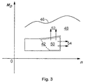
- FIG. 3 A schematic engine torque / engine speed diagram is shown in FIG. 3.
- the maximum engine torque M D depending on the speed n is given by the full load curve 46.
- an area 42 lean operation of the internal combustion engine is initiated by the engine control; Above or to the right of this area, the motor is operated stoichiometrically in an area designated by 48. Uncontrolled releases of non-converted nitrogen oxides only occur in the case of transitions from a partial area 50 of the lean area 42 (for example 52, 54). An additional regeneration cycle is therefore only triggered when the engine control system detects a transition from the subarea 50 to the area 48.
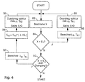
- an implementation of a monitoring loop which is carried out endlessly during engine operation according to the method according to the invention begins with the determination of the nitrogen oxide quantity value X (step 82).
- step 84 X is compared to a first threshold value S 1 .
- a basic regeneration cycle is triggered if this is exceeded.
- an air / fuel ratio ⁇ R required for regeneration and the required basic regeneration time T R1 are determined in 86 as a function of the exhaust gas temperature and the exhaust gas mass flow in the area of the nitrogen oxide trap.
- a basic regeneration cycle is then carried out at 88 and the nitrogen oxide quantity value X is reset to zero.
- X is compared with a second, lower threshold value S 2 .
- the engine controller If the engine controller detects a transition from the area 50 to the area 48 (FIG. 2) and the threshold value S 2 is exceeded, the engine controller triggers an additional regeneration cycle.
- the additional regeneration time T R2 is reduced compared to T R1 by the ratio of the current nitrogen oxide quantity value X and the threshold value S 1 (step 94).
- An additional regeneration cycle is then triggered at 96 and the nitrogen oxide quantity value X is reset to zero.
Landscapes
- Engineering & Computer Science (AREA)
- Chemical & Material Sciences (AREA)
- Combustion & Propulsion (AREA)
- Mechanical Engineering (AREA)
- General Engineering & Computer Science (AREA)
- Electrical Control Of Air Or Fuel Supplied To Internal-Combustion Engine (AREA)
- Exhaust Gas After Treatment (AREA)
Abstract
Description
- Fig. 1
- eine stark schematisierte Darstellung einer Motor-/Motorsteuerungsanordnung zur Durchführung des erfindungsgemäßen Verfahrens,
- Fig. 2
- ein schematisches Diagramm der zeitlichen Entwicklung verschiedener Motorkenngrößen,
- Fig. 3
- ein schematisches Drehzahl-/Drehmomentkennfeld zur Erläuterung des erfindungsgemäßen Verfahrens und
- Fig. 4
- ein schematisches Flußdiagramm des erfindungsgemäßen Verfahrens.
Claims (9)
- Verfahren zur Regeneration einer Stickoxidfalle (16) im Abgassystem eines Verbrennungsmotors (10) mit einer elektronischen Motorsteuerung (12), durch die abhängig von einer Vielzahl von Motorbetriebsparametern bestimmt wird, ob dem Verbrennungsmotor ein mageres oder ein im wesentlichen stöchiometrisches Luft-/Kraftstoffgemisch zugeführt wird und durch die unter vorgegebenen ersten Auslösebedingungen ein Grundregenerationszyklus der Stickoxidfalle ausgelöst wird, dadurch gekennzeichnet, daß bei einem Übergang vom mageren in den stöchiometrischem Betriebsmodus und bei einem Vorliegen von vorgegebenen zweiten Auslösebedingungen ein Zusatzregenerationszyklus der Stickoxidfalle ausgelöst wird.
- Verfahren nach Anspruch 1, dadurch gekennzeichnet, daß während beider Regenerationszyklen dem Motor (10) ein fettes Luft-/Kraftstoffgemisch zugeführt wird.
- Verfahren nach Anspruch 1 oder 2, dadurch gekennzeichnet, daß die aktuelle Stickoxidaufnahmerate der Stickoxidfalle (16) sowie ein der durch die Stickoxidfalle aufgenommenen Stickoxidmenge entsprechender Stickoxidmengenwert (X) durch zeitliche Integration der ermittelten Aufnahmerate näherungsweise durch die Motorsteuerung bestimmt wird, daß der Grundregenerationszyklus unter der Bedingung ausgelöst wird, daß der Stickoxidmengenwert einen ersten vorgegebenen Schwellwert (S1) überschreitet und der Zusatzregenerationszyklus unter der Bedingung ausgelöst wird, daß der Stickoxidmengenwert einen zweiten vorgegebenen Schwellwert (S2), der niedriger als der erste vorgegebene Schwellwert ist, überschreitet, wobei nach Ausführung eines Grund- bzw. Zusatzregenerationszyklus der Stickoxidmengenwert (X) jeweils zurückgesetzt wird.
- Verfahren nach Anspruch 3, dadurch gekennzeichnet, daß die näherungsweise Bestimmung der aktuellen Aufnahmerate von Stickoxiden anhand eines funktionalen Zusammenhangs in Abhängigkeit von aktueller Motordrehzahl, Motordrehmoment, Luft-/Kraftstoffverhältnis sowie Abgastemperatur und Abgasmassenstrom im Bereich der Stickoxidfalle (16) erfolgt.
- Verfahren nach einem der Ansprüche 1 bis 4, dadurch gekennzeichnet, daß bei Betrieb des Verbrennungsmotors mit magerem Gemisch in einem vorgegebenen Drehzahl-/Drehmomentbereich (42) ein Zusatzregenerationszyklus unter der Bedingung ausgelöst wird, daß ein Übergang aus einem vorgegebenen Teilbereich (50) des Mager-Drehzahl-/Drehmomentbereichs in einen stöchiometrischen Motorbetrieb (48) erfolgt.
- Verfahren nach Anspruch 5, dadurch gekennzeichnet, daß der Teilbereich (50) des Magerbetriebsbereichs (42) in einem Bereich höherer Drehzahlen bzw. Drehmomente liegt.
- Verfahren nach einem der Ansprüche 3 bis 6, dadurch gekennzeichnet, daß ein zur Regeneration der Stickoxidfalle erforderliches fettes Regenerations-Luft-/Kraftstoffverhältnis anhand eines funktionalen Zusammenhangs abhängig von der Abgastemperatur im Bereich der Stickoxidfalle und dem Abgasmassenstrom bestimmt wird.
- Verfahren nach Anspruch 7, dadurch gekennzeichnet, daß eine zur Durchführung eines Grundregenerationszyklus mit dem Regenerations-Luft-/Kraftstoffverhältnis benötigte Grundregenerationszeit (TR1) anhand eines funktionalen Zusammenhangs abhängig von der Abgastemperatur und dem Abgasmassenstrom im Bereich der Stickoxidfalle bestimmt wird.
- Verfahren nach Anspruch 8, dadurch gekennzeichnet, daß eine zur Durchführung eines Zusatzregenerationszyklus mit dem Regenerations-Luft-/Kraftstoffverhältnis benötigte Zusatzregenerationszeit durch Multiplikation der Grundregenerationszeit (TR2) mit dem Verhältnis aus aktuellem Stickoxidmengenwert (X) zu erstem Schwellwert (S1) und Addition einer vorgegebenen Offsetzeit zu dem Produkt bestimmt wird.
Applications Claiming Priority (2)
| Application Number | Priority Date | Filing Date | Title |
|---|---|---|---|
| DE19741079A DE19741079C2 (de) | 1997-09-18 | 1997-09-18 | Verfahren zur Regeneration einer Stickoxidfalle im Abgassystem eines Verbrennungsmotors |
| DE19741079 | 1997-09-18 |
Publications (3)
| Publication Number | Publication Date |
|---|---|
| EP0903477A2 true EP0903477A2 (de) | 1999-03-24 |
| EP0903477A3 EP0903477A3 (de) | 2000-03-08 |
| EP0903477B1 EP0903477B1 (de) | 2002-03-20 |
Family
ID=7842756
Family Applications (1)
| Application Number | Title | Priority Date | Filing Date |
|---|---|---|---|
| EP98113275A Expired - Lifetime EP0903477B1 (de) | 1997-09-18 | 1998-07-16 | Verfahren zur Regeneration einer Stickoxidfalle im Abgassystem eines Verbrennungsmotors |
Country Status (3)
| Country | Link |
|---|---|
| EP (1) | EP0903477B1 (de) |
| JP (1) | JP4099272B2 (de) |
| DE (2) | DE19741079C2 (de) |
Cited By (5)
| Publication number | Priority date | Publication date | Assignee | Title |
|---|---|---|---|---|
| EP1083323A2 (de) * | 1999-09-09 | 2001-03-14 | Toyota Jidosha Kabushiki Kaisha | Abgasreinigungsanlage für eine Brennkraftmaschine |
| WO2001018367A1 (de) * | 1999-09-04 | 2001-03-15 | Robert Bosch Gmbh | Verfahren zum betreiben einer brennkraftmaschine |
| EP1054149A3 (de) * | 1999-05-18 | 2002-07-17 | Toyota Jidosha Kabushiki Kaisha | Steuerer eines Verbrennungsmotors |
| RU2598968C2 (ru) * | 2012-04-10 | 2016-10-10 | Вольво Ластвагнар Аб | Способ автоматической диагностики системы селективного каталитического восстановления |
| EP3098423A1 (de) * | 2015-05-11 | 2016-11-30 | Toyota Jidosha Kabushiki Kaisha | Steuerungsvorrichtung für einen verbrennungsmotor |
Families Citing this family (7)
| Publication number | Priority date | Publication date | Assignee | Title |
|---|---|---|---|---|
| DE10020789C2 (de) * | 1999-05-19 | 2003-05-08 | Ford Global Tech Inc | Verfahren und System für den Übergang zwischen magerem und stöchiometrischem Kraftstoff-Luft-Verhältnis in einem mit magerer Verbrennung betriebenen Motor |
| JP3854013B2 (ja) * | 1999-06-10 | 2006-12-06 | 三菱電機株式会社 | 内燃機関の排出ガス浄化装置 |
| DE19932301A1 (de) * | 1999-07-10 | 2001-01-11 | Volkswagen Ag | Verfahren zur Regelung einer Regeneration eines in einem Abgaskanal einer Verbrennungskraftmaschine angeordneten Speicherkatalysators |
| DE19963938A1 (de) * | 1999-12-31 | 2001-07-12 | Bosch Gmbh Robert | Verfahren zum Betreiben eines Dreiwegekatalysators einer Brennkraftmaschine |
| DE10054005A1 (de) | 2000-11-01 | 2002-05-08 | Daimler Chrysler Ag | Verfahren zum Betrieb einer Abgasreinigungsanlage mit Stickoxidspeicher |
| US6915630B2 (en) * | 2003-01-27 | 2005-07-12 | Ford Global Technologies, Llc | Engine control for a vehicle equipped with an emission control device |
| DE202013008389U1 (de) * | 2013-09-21 | 2014-12-22 | GM Global Technology Operations LLC (n. d. Gesetzen des Staates Delaware) | Steueranordnung zum Steuern einer Brennkraftmaschine eines Kraftfahrzeugs |
Family Cites Families (5)
| Publication number | Priority date | Publication date | Assignee | Title |
|---|---|---|---|---|
| EP0598917B2 (de) * | 1992-06-12 | 2009-04-15 | Toyota Jidosha Kabushiki Kaisha | Abgasemissionssteuerungssystem für verbrennungsmotoren |
| WO1993025805A1 (fr) * | 1992-06-12 | 1993-12-23 | Toyota Jidosha Kabushiki Kaisha | Systeme de limitation d'emission de gaz d'echappement pour moteur a combustion interne |
| JP2692530B2 (ja) * | 1992-09-02 | 1997-12-17 | トヨタ自動車株式会社 | 内燃機関 |
| DE19626835A1 (de) * | 1995-07-08 | 1997-01-09 | Volkswagen Ag | Dieselbrennkraftmaschine mit NOx-Speicher |
| DE19607151C1 (de) * | 1996-02-26 | 1997-07-10 | Siemens Ag | Verfahren zur Regeneration eines NOx-Speicherkatalysators |
-
1997
- 1997-09-18 DE DE19741079A patent/DE19741079C2/de not_active Expired - Fee Related
-
1998
- 1998-07-16 EP EP98113275A patent/EP0903477B1/de not_active Expired - Lifetime
- 1998-07-16 DE DE59803414T patent/DE59803414D1/de not_active Expired - Fee Related
- 1998-09-07 JP JP27055098A patent/JP4099272B2/ja not_active Expired - Fee Related
Cited By (8)
| Publication number | Priority date | Publication date | Assignee | Title |
|---|---|---|---|---|
| EP1054149A3 (de) * | 1999-05-18 | 2002-07-17 | Toyota Jidosha Kabushiki Kaisha | Steuerer eines Verbrennungsmotors |
| WO2001018367A1 (de) * | 1999-09-04 | 2001-03-15 | Robert Bosch Gmbh | Verfahren zum betreiben einer brennkraftmaschine |
| US6758034B1 (en) | 1999-09-04 | 2004-07-06 | Robert Bosch Gmbh | Method for operating an internal combustion engine |
| RU2247251C2 (ru) * | 1999-09-04 | 2005-02-27 | Роберт Бош Гмбх | Способ управления работой двигателя внутреннего сгорания |
| EP1083323A2 (de) * | 1999-09-09 | 2001-03-14 | Toyota Jidosha Kabushiki Kaisha | Abgasreinigungsanlage für eine Brennkraftmaschine |
| RU2598968C2 (ru) * | 2012-04-10 | 2016-10-10 | Вольво Ластвагнар Аб | Способ автоматической диагностики системы селективного каталитического восстановления |
| EP3098423A1 (de) * | 2015-05-11 | 2016-11-30 | Toyota Jidosha Kabushiki Kaisha | Steuerungsvorrichtung für einen verbrennungsmotor |
| US10316776B2 (en) | 2015-05-11 | 2019-06-11 | Toyota Jidosha Kabushiki Kaisha | Control apparatus for an internal combustion engine |
Also Published As
| Publication number | Publication date |
|---|---|
| JP4099272B2 (ja) | 2008-06-11 |
| DE19741079C2 (de) | 2001-10-18 |
| DE59803414D1 (de) | 2002-04-25 |
| JPH11148338A (ja) | 1999-06-02 |
| EP0903477A3 (de) | 2000-03-08 |
| EP0903477B1 (de) | 2002-03-20 |
| DE19741079A1 (de) | 1999-04-01 |
Similar Documents
| Publication | Publication Date | Title |
|---|---|---|
| EP1090220B1 (de) | VERFAHREN ZUR REGENERATION EINES NOx-SPEICHERKATALYSATORS FÜR EINE BRENNKRAFTMASCHINE | |
| EP1097299A1 (de) | VERFAHREN ZUR ÜBERPRÜFUNG DES WIRKUNGSGRADES EINES NOx-SPEICHERKATALYSATORS | |
| DE10056016A1 (de) | Verfahren und Vorrichtung zur Steuerung eines Abgasnachbehandlungssystems | |
| DE10036453A1 (de) | Verfahren und Steuergerät zum Betreiben eines Stickoxid (NOx)-Speicherkatalysators | |
| DE3714151A1 (de) | Steuereinrichtung fuer die drosselklappe eines verbrennungsmotors | |
| EP0858837A2 (de) | Verfahren zur Regeneration eines Speicherkatalysators | |
| EP1307640A1 (de) | VERFAHREN ZUM BETREIBEN EINES STICKOXID (NOx)-SPEICHERKATALYSATORS | |
| EP0903477B1 (de) | Verfahren zur Regeneration einer Stickoxidfalle im Abgassystem eines Verbrennungsmotors | |
| EP1193376B1 (de) | Regelung eines NOx-Speicherkatalysators | |
| EP1259718B8 (de) | Vorrichtung und verfahren zur steuerung einer nox-regeneration eines nox-speicherkatalysators | |
| EP1192343B1 (de) | VERFAHREN ZUR INITIIERUNG UND ÜBERWACHUNG EINER ENTSCHWELFELUNG VON WENIGSTENS EINEM IN EINEM ABGASKANAL EINER VERBRENNUNGSKRAFTMASCHINE ANGEORDNETEN NOx-SPEICHERKATALYSATOR | |
| DE19706607B4 (de) | Verfahren zur drehmomentsprungreduzierten Regeneration einer Stickoxidfalle im Abgassystem eines Verbrennungsmotors sowie Vorrichtung zur Durchführung des Verfahrens | |
| WO2002014658A1 (de) | VERFAHREN UND STEUERGERÄT ZUM BESTIMMEN DES ZUSTANDS EINES STICKOXID (NOx)-SPEICHERKATALYSATORS | |
| EP0937876B1 (de) | Verfahren zur Regeneration einer Stickoxidfalle im Abgassystem eines Verbrennungsmotors | |
| DE19963901A1 (de) | Verfahren zum Betreiben eines Katalysators einer Brennkraftmaschine | |
| EP1230471A1 (de) | Verfahren zum betreiben eines speicherkatalysators einer brennkraftmaschine | |
| EP1247006B1 (de) | Verfahren zum betreiben eines speicherkatalysators einer brennkraftmaschine | |
| DE19609922B4 (de) | Sekundärluftsystemdiagnoseverfahren | |
| DE10249609B4 (de) | Verfahren zur Steuerung eines NOx-Speicherkatalysators | |
| DE102021205510A1 (de) | Verfahren zum Betreiben eines Fahrzeugs mit einer Brennkraftmaschine und einem Automatikgetriebe | |
| DE102005049770B4 (de) | Verfahren zum Betreiben einer Brennkraftmaschine und Vorrichtung zur Durchführung des Verfahrens | |
| DE10051012A1 (de) | Verfahren und Vorrichtung zum Diagnostizieren der Speichereigenschaften eines NOx-Speicherkatalysators | |
| DE102019131022B4 (de) | Verfahren und system zum steuern einer sauerstoffreinigung eines drei- wege-katalysators | |
| DE69909147T2 (de) | Verfahren zur Funktionsüberwachung des Abgaskatalysators eines Kraftfahrzeuges | |
| DE102022210290A1 (de) | Verfahren zur Regelung des Sauerstoff-Füllstands eines Katalysators im Abgas eines Verbrennungsmotors |
Legal Events
| Date | Code | Title | Description |
|---|---|---|---|
| PUAI | Public reference made under article 153(3) epc to a published international application that has entered the european phase |
Free format text: ORIGINAL CODE: 0009012 |
|
| AK | Designated contracting states |
Kind code of ref document: A2 Designated state(s): DE FR GB IT SE |
|
| AX | Request for extension of the european patent |
Free format text: AL;LT;LV;MK;RO;SI |
|
| PUAL | Search report despatched |
Free format text: ORIGINAL CODE: 0009013 |
|
| AK | Designated contracting states |
Kind code of ref document: A3 Designated state(s): AT BE CH CY DE DK ES FI FR GB GR IE IT LI LU MC NL PT SE |
|
| AX | Request for extension of the european patent |
Free format text: AL;LT;LV;MK;RO;SI |
|
| 17P | Request for examination filed |
Effective date: 20000329 |
|
| AKX | Designation fees paid |
Free format text: DE FR GB IT SE |
|
| GRAG | Despatch of communication of intention to grant |
Free format text: ORIGINAL CODE: EPIDOS AGRA |
|
| GRAG | Despatch of communication of intention to grant |
Free format text: ORIGINAL CODE: EPIDOS AGRA |
|
| GRAH | Despatch of communication of intention to grant a patent |
Free format text: ORIGINAL CODE: EPIDOS IGRA |
|
| 17Q | First examination report despatched |
Effective date: 20010726 |
|
| GRAH | Despatch of communication of intention to grant a patent |
Free format text: ORIGINAL CODE: EPIDOS IGRA |
|
| REG | Reference to a national code |
Ref country code: GB Ref legal event code: IF02 |
|
| GRAA | (expected) grant |
Free format text: ORIGINAL CODE: 0009210 |
|
| AK | Designated contracting states |
Kind code of ref document: B1 Designated state(s): DE FR GB IT SE |
|
| PG25 | Lapsed in a contracting state [announced via postgrant information from national office to epo] |
Ref country code: IT Free format text: LAPSE BECAUSE OF FAILURE TO SUBMIT A TRANSLATION OF THE DESCRIPTION OR TO PAY THE FEE WITHIN THE PRE;WARNING: LAPSES OF ITALIAN PATENTS WITH EFFECTIVE DATE BEFORE 2007 MAY HAVE OCCURRED AT ANY TIME BEFORE 2007. THE CORRECT EFFECTIVE DATE MAY BE DIFFERENT FROM THE ONE RECORDED.SCRIBED TIME-LIMIT Effective date: 20020320 |
|
| GBT | Gb: translation of ep patent filed (gb section 77(6)(a)/1977) |
Effective date: 20020320 |
|
| REF | Corresponds to: |
Ref document number: 59803414 Country of ref document: DE Date of ref document: 20020425 |
|
| PG25 | Lapsed in a contracting state [announced via postgrant information from national office to epo] |
Ref country code: SE Free format text: LAPSE BECAUSE OF FAILURE TO SUBMIT A TRANSLATION OF THE DESCRIPTION OR TO PAY THE FEE WITHIN THE PRESCRIBED TIME-LIMIT Effective date: 20020620 |
|
| PGFP | Annual fee paid to national office [announced via postgrant information from national office to epo] |
Ref country code: SE Payment date: 20020625 Year of fee payment: 5 |
|
| ET | Fr: translation filed | ||
| PLBE | No opposition filed within time limit |
Free format text: ORIGINAL CODE: 0009261 |
|
| STAA | Information on the status of an ep patent application or granted ep patent |
Free format text: STATUS: NO OPPOSITION FILED WITHIN TIME LIMIT |
|
| 26N | No opposition filed |
Effective date: 20021223 |
|
| REG | Reference to a national code |
Ref country code: GB Ref legal event code: 732E |
|
| REG | Reference to a national code |
Ref country code: FR Ref legal event code: TP |
|
| REG | Reference to a national code |
Ref country code: GB Ref legal event code: 746 Effective date: 20060707 |
|
| PGFP | Annual fee paid to national office [announced via postgrant information from national office to epo] |
Ref country code: FR Payment date: 20090708 Year of fee payment: 12 |
|
| PGFP | Annual fee paid to national office [announced via postgrant information from national office to epo] |
Ref country code: GB Payment date: 20090612 Year of fee payment: 12 Ref country code: DE Payment date: 20090730 Year of fee payment: 12 |
|
| GBPC | Gb: european patent ceased through non-payment of renewal fee |
Effective date: 20100716 |
|
| REG | Reference to a national code |
Ref country code: FR Ref legal event code: ST Effective date: 20110331 |
|
| PG25 | Lapsed in a contracting state [announced via postgrant information from national office to epo] |
Ref country code: DE Free format text: LAPSE BECAUSE OF NON-PAYMENT OF DUE FEES Effective date: 20110201 |
|
| REG | Reference to a national code |
Ref country code: DE Ref legal event code: R119 Ref document number: 59803414 Country of ref document: DE Effective date: 20110201 |
|
| PG25 | Lapsed in a contracting state [announced via postgrant information from national office to epo] |
Ref country code: FR Free format text: LAPSE BECAUSE OF NON-PAYMENT OF DUE FEES Effective date: 20100802 |
|
| PG25 | Lapsed in a contracting state [announced via postgrant information from national office to epo] |
Ref country code: GB Free format text: LAPSE BECAUSE OF NON-PAYMENT OF DUE FEES Effective date: 20100716 |