EP0903477A2 - Regeneration method of a nitrogen oxides trap in the exhaust system of an internal combustion engine - Google Patents
Regeneration method of a nitrogen oxides trap in the exhaust system of an internal combustion engine Download PDFInfo
- Publication number
- EP0903477A2 EP0903477A2 EP98113275A EP98113275A EP0903477A2 EP 0903477 A2 EP0903477 A2 EP 0903477A2 EP 98113275 A EP98113275 A EP 98113275A EP 98113275 A EP98113275 A EP 98113275A EP 0903477 A2 EP0903477 A2 EP 0903477A2
- Authority
- EP
- European Patent Office
- Prior art keywords
- nitrogen oxide
- regeneration
- lean
- engine
- regeneration cycle
- Prior art date
- Legal status (The legal status is an assumption and is not a legal conclusion. Google has not performed a legal analysis and makes no representation as to the accuracy of the status listed.)
- Granted
Links
Images


Classifications
-
- F—MECHANICAL ENGINEERING; LIGHTING; HEATING; WEAPONS; BLASTING
- F01—MACHINES OR ENGINES IN GENERAL; ENGINE PLANTS IN GENERAL; STEAM ENGINES
- F01N—GAS-FLOW SILENCERS OR EXHAUST APPARATUS FOR MACHINES OR ENGINES IN GENERAL; GAS-FLOW SILENCERS OR EXHAUST APPARATUS FOR INTERNAL-COMBUSTION ENGINES
- F01N3/00—Exhaust or silencing apparatus having means for purifying, rendering innocuous, or otherwise treating exhaust
- F01N3/08—Exhaust or silencing apparatus having means for purifying, rendering innocuous, or otherwise treating exhaust for rendering innocuous
- F01N3/0807—Exhaust or silencing apparatus having means for purifying, rendering innocuous, or otherwise treating exhaust for rendering innocuous by using absorbents or adsorbents
- F01N3/0828—Exhaust or silencing apparatus having means for purifying, rendering innocuous, or otherwise treating exhaust for rendering innocuous by using absorbents or adsorbents characterised by the absorbed or adsorbed substances
- F01N3/0842—Nitrogen oxides
-
- F—MECHANICAL ENGINEERING; LIGHTING; HEATING; WEAPONS; BLASTING
- F01—MACHINES OR ENGINES IN GENERAL; ENGINE PLANTS IN GENERAL; STEAM ENGINES
- F01N—GAS-FLOW SILENCERS OR EXHAUST APPARATUS FOR MACHINES OR ENGINES IN GENERAL; GAS-FLOW SILENCERS OR EXHAUST APPARATUS FOR INTERNAL-COMBUSTION ENGINES
- F01N3/00—Exhaust or silencing apparatus having means for purifying, rendering innocuous, or otherwise treating exhaust
- F01N3/08—Exhaust or silencing apparatus having means for purifying, rendering innocuous, or otherwise treating exhaust for rendering innocuous
- F01N3/0807—Exhaust or silencing apparatus having means for purifying, rendering innocuous, or otherwise treating exhaust for rendering innocuous by using absorbents or adsorbents
- F01N3/0871—Exhaust or silencing apparatus having means for purifying, rendering innocuous, or otherwise treating exhaust for rendering innocuous by using absorbents or adsorbents using means for controlling, e.g. purging, the absorbents or adsorbents
-
- F—MECHANICAL ENGINEERING; LIGHTING; HEATING; WEAPONS; BLASTING
- F02—COMBUSTION ENGINES; HOT-GAS OR COMBUSTION-PRODUCT ENGINE PLANTS
- F02D—CONTROLLING COMBUSTION ENGINES
- F02D41/00—Electrical control of supply of combustible mixture or its constituents
- F02D41/02—Circuit arrangements for generating control signals
- F02D41/021—Introducing corrections for particular conditions exterior to the engine
- F02D41/0235—Introducing corrections for particular conditions exterior to the engine in relation with the state of the exhaust gas treating apparatus
- F02D41/027—Introducing corrections for particular conditions exterior to the engine in relation with the state of the exhaust gas treating apparatus to purge or regenerate the exhaust gas treating apparatus
- F02D41/0275—Introducing corrections for particular conditions exterior to the engine in relation with the state of the exhaust gas treating apparatus to purge or regenerate the exhaust gas treating apparatus the exhaust gas treating apparatus being a NOx trap or adsorbent
-
- F—MECHANICAL ENGINEERING; LIGHTING; HEATING; WEAPONS; BLASTING
- F02—COMBUSTION ENGINES; HOT-GAS OR COMBUSTION-PRODUCT ENGINE PLANTS
- F02D—CONTROLLING COMBUSTION ENGINES
- F02D41/00—Electrical control of supply of combustible mixture or its constituents
- F02D41/02—Circuit arrangements for generating control signals
- F02D41/14—Introducing closed-loop corrections
- F02D41/1438—Introducing closed-loop corrections using means for determining characteristics of the combustion gases; Sensors therefor
- F02D41/1444—Introducing closed-loop corrections using means for determining characteristics of the combustion gases; Sensors therefor characterised by the characteristics of the combustion gases
- F02D41/1446—Introducing closed-loop corrections using means for determining characteristics of the combustion gases; Sensors therefor characterised by the characteristics of the combustion gases the characteristics being exhaust temperatures
-
- F—MECHANICAL ENGINEERING; LIGHTING; HEATING; WEAPONS; BLASTING
- F02—COMBUSTION ENGINES; HOT-GAS OR COMBUSTION-PRODUCT ENGINE PLANTS
- F02D—CONTROLLING COMBUSTION ENGINES
- F02D41/00—Electrical control of supply of combustible mixture or its constituents
- F02D41/02—Circuit arrangements for generating control signals
- F02D41/14—Introducing closed-loop corrections
- F02D41/1438—Introducing closed-loop corrections using means for determining characteristics of the combustion gases; Sensors therefor
- F02D41/1444—Introducing closed-loop corrections using means for determining characteristics of the combustion gases; Sensors therefor characterised by the characteristics of the combustion gases
- F02D41/146—Introducing closed-loop corrections using means for determining characteristics of the combustion gases; Sensors therefor characterised by the characteristics of the combustion gases the characteristics being an NOx content or concentration
- F02D41/1461—Introducing closed-loop corrections using means for determining characteristics of the combustion gases; Sensors therefor characterised by the characteristics of the combustion gases the characteristics being an NOx content or concentration of the exhaust gases emitted by the engine
- F02D41/1462—Introducing closed-loop corrections using means for determining characteristics of the combustion gases; Sensors therefor characterised by the characteristics of the combustion gases the characteristics being an NOx content or concentration of the exhaust gases emitted by the engine with determination means using an estimation
-
- F—MECHANICAL ENGINEERING; LIGHTING; HEATING; WEAPONS; BLASTING
- F02—COMBUSTION ENGINES; HOT-GAS OR COMBUSTION-PRODUCT ENGINE PLANTS
- F02D—CONTROLLING COMBUSTION ENGINES
- F02D41/00—Electrical control of supply of combustible mixture or its constituents
- F02D41/30—Controlling fuel injection
- F02D41/38—Controlling fuel injection of the high pressure type
- F02D2041/389—Controlling fuel injection of the high pressure type for injecting directly into the cylinder
-
- F—MECHANICAL ENGINEERING; LIGHTING; HEATING; WEAPONS; BLASTING
- F02—COMBUSTION ENGINES; HOT-GAS OR COMBUSTION-PRODUCT ENGINE PLANTS
- F02D—CONTROLLING COMBUSTION ENGINES
- F02D2200/00—Input parameters for engine control
- F02D2200/02—Input parameters for engine control the parameters being related to the engine
- F02D2200/08—Exhaust gas treatment apparatus parameters
- F02D2200/0806—NOx storage amount, i.e. amount of NOx stored on NOx trap
-
- F—MECHANICAL ENGINEERING; LIGHTING; HEATING; WEAPONS; BLASTING
- F02—COMBUSTION ENGINES; HOT-GAS OR COMBUSTION-PRODUCT ENGINE PLANTS
- F02D—CONTROLLING COMBUSTION ENGINES
- F02D41/00—Electrical control of supply of combustible mixture or its constituents
- F02D41/02—Circuit arrangements for generating control signals
- F02D41/18—Circuit arrangements for generating control signals by measuring intake air flow
- F02D41/187—Circuit arrangements for generating control signals by measuring intake air flow using a hot wire flow sensor
Definitions
- the invention relates to a method for the regeneration of a Nitrogen oxide trap in the exhaust system of an internal combustion engine an electronic engine control system, depending on a variety of engine operating parameters determine whether the internal combustion engine lean or essentially stoichiometric air / fuel mixture is supplied and by the given first trigger conditions Basic regeneration cycle of the nitrogen oxide trap is triggered.
- Such a nitrogen oxide trap is preferably used in conjunction with a conventional three-way catalytic converter in motor vehicles whose internal combustion engine is designed for lean operation (lean burn engine) in order to reduce the nitrogen oxide emissions which occur in particular in lean operation.
- the nitrogen oxide molecules are attached to the coating of the trap and thus removed from the exhaust gas.
- a regeneration cycle is required when a certain degree of saturation is reached.
- a problem with known nitrogen oxide traps is that it occurs under certain operating conditions can that already bound nitrogen oxides unconverted from the Nitrogen oxide trap are released again. This occurs in particular then when lean of the engine in higher speed / torque ranges in one stoichiometric operation. if the Nitric oxide trap already at the time of this transition If there is a large amount of nitrogen oxide stored, it can Unconverted nitrogen oxides are released. Such Uncontrolled release of nitrogen oxides can do this lead to stringent exhaust gas tests despite satisfactory exhaust gas values fail in stationary operation.
- the invention has for its object a method of to create the type mentioned above, with the emission peaks be avoided lean-stoichiometric at the transition, whereby to ensure that the engine in one possible large speed / torque range can be operated lean can.
- This object is achieved in that a transition from the lean to the stoichiometric operating mode and if there are predetermined second ones Trigger conditions an additional regeneration cycle of the Nitrogen oxide trap is triggered. Through this additional regeneration cycle the nitrogen oxide trap before the transition to the regenerated stoichiometric mode, leaving an uncontrolled The release of stored nitrogen oxides is no longer possible is.
- the regeneration cycles are preferred the invention, characterized in that the engine is a rich Air / fuel mixture is supplied.
- the current nitrogen oxide uptake rate of Nitric oxide trap and one of those taken up by the nitrogen oxide trap Corresponding nitrogen oxide quantity value through temporal integration of the determined admission rate approximately it is determined by the engine controller that the Basic regeneration cycle triggered under the (first) condition is that the nitrogen oxide amount value is given a first Threshold exceeds and the additional regeneration cycle triggered under the (second) condition is that the nitrogen oxide amount value given a second Threshold that is lower than the first given Threshold is exceeded, whereby after execution of a Basic or additional regeneration cycle of the nitrogen oxide quantity value is reset in each case.
- An additional regeneration the nitrogen oxide trap is therefore preferably not used every transition lean-stoichiometric, but only if a certain minimum amount of nitrogen oxides is also stored is. This eliminates unnecessary regeneration cycles, each with an increased fuel consumption are avoided.
- the basic regeneration cycle timer controlled at regular intervals perform and the additional regeneration cycle at each Initiate lean-stoichiometric transition.
- Alternative is it is still conceivable to have an additional regeneration cycle only under the additional trigger condition to allow that since a certain minimum time elapsed after the last regeneration is.
- Embodiment of the invention can be provided that during operation of the internal combustion engine with a lean mixture in a predetermined Speed / torque range an additional regeneration cycle on the condition that a transition is triggered from a specified subrange of the lean speed / torque range into stoichiometric engine operation he follows.
- the partial area of the lean operating area is preferably located in a range of higher speeds or Torques.
- a regeneration of the Nitric oxide trap requires a rich regeneration air / fuel ratio based on a functional relationship depending on the exhaust gas temperature in the range of Nitrogen oxide trap and the exhaust gas mass flow is determined.
- the so certain regeneration air / fuel ratio can preferably both during the basic and during the Additional regeneration cycle are used.
- Basic regeneration time for regeneration with the regeneration air / fuel ratio can preferably be based on a functional relationship depending on the exhaust gas temperature and the exhaust gas mass flow in the range of Nitrogen oxide trap can be determined.
- additional regeneration time required can preferably by multiplying the basic regeneration time by the ratio of the current nitrogen oxide quantity value to the first Threshold are determined. This takes into account that the nitrogen oxide trap when performing the additional regeneration cycle generally less than saved in the case of the basic regeneration cycle, so that the regeneration time can be reduced accordingly can to minimize the fuel consumption.
- a fixed offset value is added at the regeneration times determined in the manner described above. This takes into account the time that the fat peak from Internal combustion engine over a three-way catalyst needs to to get to the nitrogen oxide trap.
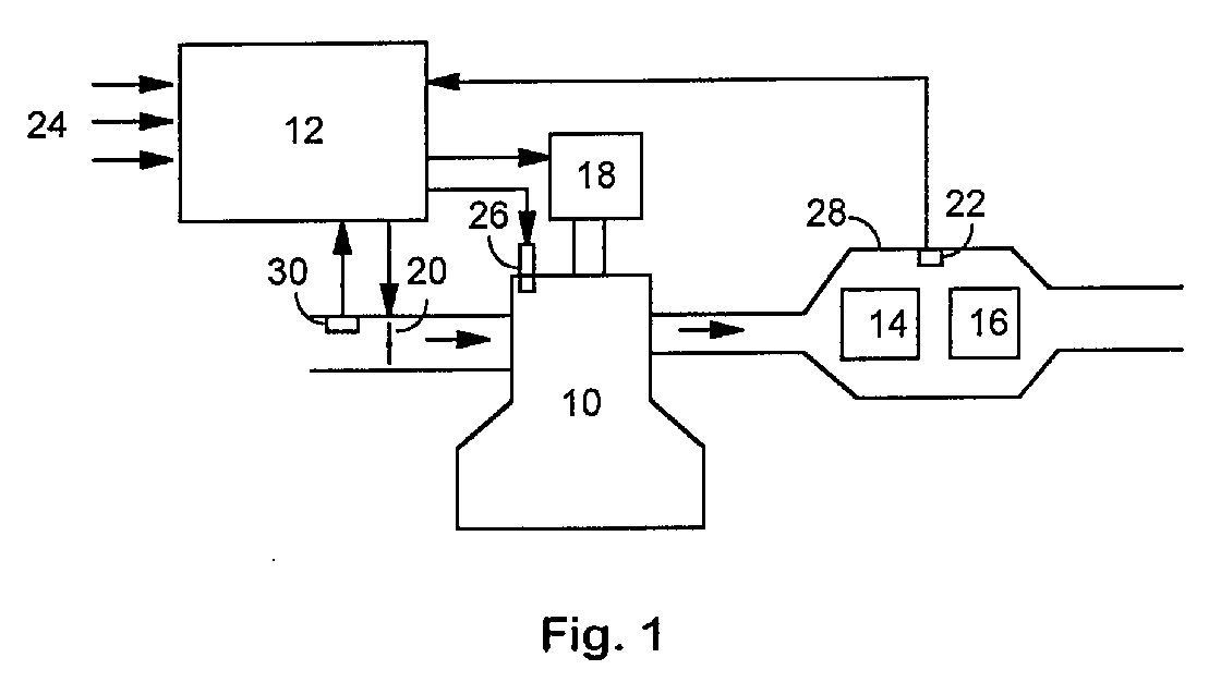
- a multi-cylinder internal combustion engine 10 from an electronic engine controller 12 that has a variety of input signals 24, e.g. the current engine speed, a signal from an air / mass flow sensor 30 in the intake duct or get the current position of the accelerator pedal, controlled.
- the engine control leads to algorithms Control of an electronic throttle valve 20, one Ignition system 18 and an injection system 26.
- the air / fuel ratio ⁇ of the supplied to the cylinders Mixtures can be changed within wide limits, in particular may be lean under certain operating conditions Air / fuel ratio can be set.
- the engine exhaust are supplied to an exhaust gas treatment arrangement 28. This consists of a three-way catalyst 14 and a nitrogen oxide trap 16.
- a temperature sensor 22 becomes the exhaust gas temperature in close proximity to the exhaust treatment arrangement 28 measured.
- FIG. 2 shows the development over time of the nitrogen oxide quantity value X taken up by the nitrogen oxide trap, the set air / fuel ratio ⁇ and a value NO x representing the nitrogen oxide emissions.
- the engine control calculates the current nitrogen oxide uptake rate in discrete time intervals based on a functional relationship depending on the current engine speed, engine torque, air / fuel ratio and exhaust gas temperature and exhaust gas mass flow and integrates this rate into a nitrogen oxide quantity value X. If this exceeds a threshold value S 1 (60), it is exceeded for a period of time T R1, a basic regeneration cycle with a regeneration air / fuel ratio of 0.75 was carried out and the nitrogen oxide quantity value was then reset to zero.
- S 1 60
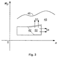
- FIG. 3 A schematic engine torque / engine speed diagram is shown in FIG. 3.
- the maximum engine torque M D depending on the speed n is given by the full load curve 46.
- an area 42 lean operation of the internal combustion engine is initiated by the engine control; Above or to the right of this area, the motor is operated stoichiometrically in an area designated by 48. Uncontrolled releases of non-converted nitrogen oxides only occur in the case of transitions from a partial area 50 of the lean area 42 (for example 52, 54). An additional regeneration cycle is therefore only triggered when the engine control system detects a transition from the subarea 50 to the area 48.
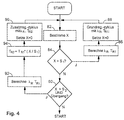
- an implementation of a monitoring loop which is carried out endlessly during engine operation according to the method according to the invention begins with the determination of the nitrogen oxide quantity value X (step 82).
- step 84 X is compared to a first threshold value S 1 .
- a basic regeneration cycle is triggered if this is exceeded.
- an air / fuel ratio ⁇ R required for regeneration and the required basic regeneration time T R1 are determined in 86 as a function of the exhaust gas temperature and the exhaust gas mass flow in the area of the nitrogen oxide trap.
- a basic regeneration cycle is then carried out at 88 and the nitrogen oxide quantity value X is reset to zero.
- X is compared with a second, lower threshold value S 2 .
- the engine controller If the engine controller detects a transition from the area 50 to the area 48 (FIG. 2) and the threshold value S 2 is exceeded, the engine controller triggers an additional regeneration cycle.
- the additional regeneration time T R2 is reduced compared to T R1 by the ratio of the current nitrogen oxide quantity value X and the threshold value S 1 (step 94).
- An additional regeneration cycle is then triggered at 96 and the nitrogen oxide quantity value X is reset to zero.
Landscapes
- Engineering & Computer Science (AREA)
- Chemical & Material Sciences (AREA)
- Combustion & Propulsion (AREA)
- Mechanical Engineering (AREA)
- General Engineering & Computer Science (AREA)
- Electrical Control Of Air Or Fuel Supplied To Internal-Combustion Engine (AREA)
- Exhaust Gas After Treatment (AREA)
Abstract
Die Erfindung betrifft ein Verfahren zur Regeneration einer
Stickoxidfalle (16) im Abgassystem eines Verbrennungsmotors
(10) mit einer elektronischen Motorsteuerung (12), durch die
abhängig von einer Vielzahl von Motorbetriebsparametern bestimmt
wird, ob dem Verbrennungsmotor ein mageres oder ein
im wesentlichen stöchiometrisches Luft-/Kraftstoffgemisch
zugeführt wird und durch die unter vorgegebenen ersten Auslösebedingungen
ein Grundregenerationszyklus der Stickoxidfalle
ausgelöst wird. Bei einem Übergang vom mageren in den
stöchiometrischen Betriebsmodus und bei einem Vorliegen von
vorgegebenen zweiten Auslösebedingungen wird ein Zusatzregenerationszyklus
der Stickoxidfalle ausgelöst. Damit wird eine
unkontrollierte Freisetzung von gespeicherten Stickoxiden
aus der Stickoxidfalle vermieden. Der Zusatzregenerationszyklus
wird vorzugsweise nur dann ausgelöst, wenn die aufgenommene
Stickoxidmenge (X) einen bestimmten Schwellwert hat
und der Übergang in den stöchiometrischen Betrieb aus einem
vorgegebenen Teilbereich des Mager-Drehzahl-/Drehmomentbereichs
erfolgt.
Description
Die Erfindung betrifft ein Verfahren zur Regeneration einer Stickoxidfalle im Abgassystem eines Verbrennungsmotors mit einer elektronischen Motorsteuerung, durch die abhängig von einer Vielzahl von Motorbetriebsparametern bestimmt wird, ob dem Verbrennungsmotor ein mageres oder ein im wesentlichen stöchiometrisches Luft-/Kraftstoffgemisch zugeführt wird und durch die unter vorgegebenen ersten Auslösebedingungen ein Grundregenerationszyklus der Stickoxidfalle ausgelöst wird.The invention relates to a method for the regeneration of a Nitrogen oxide trap in the exhaust system of an internal combustion engine an electronic engine control system, depending on a variety of engine operating parameters determine whether the internal combustion engine lean or essentially stoichiometric air / fuel mixture is supplied and by the given first trigger conditions Basic regeneration cycle of the nitrogen oxide trap is triggered.
Der Einsatz einer derartigen Stickoxidfalle (NOx-Trap) im Verbund mit einem konventionellen Dreiwegekatalysator erfolgt bevorzugt bei Kraftfahrzeugen, deren Verbrennungsmotor für einen Magerbetrieb ausgelegt ist (lean burn engine), um die insbesondere im Magerbetrieb auftretenden Stickoxidemissionen zu verringern. Die Stickoxidmoleküle werden an der Beschichtung der Falle angelagert und damit aus dem Abgas entfernt. Um einen dauerhaften Betrieb der Stickoxidfalle zu ermöglichen, ist bei Erreichen eines bestimmten Sättigungsgrades ein Regenerationszyklus erforderlich. Hierzu wird der Motor üblicherweise für kurze Zeit mit einem fetten Luft-/Kraftstoffgemisch (z.B. λ = 0,75) betrieben. Die angelagerten Stickoxide werden unter diesen Bedingungen unter Einwirkung eines Katalysators zu Stickstoff und Sauerstoff aufgespalten, wobei der Sauerstoff mit überschüssigem Wasserstoff oder CO zu Wasser bzw. CO2 verbrannt wird.Such a nitrogen oxide trap (NO x trap) is preferably used in conjunction with a conventional three-way catalytic converter in motor vehicles whose internal combustion engine is designed for lean operation (lean burn engine) in order to reduce the nitrogen oxide emissions which occur in particular in lean operation. The nitrogen oxide molecules are attached to the coating of the trap and thus removed from the exhaust gas. In order to enable the nitrogen oxide trap to operate continuously, a regeneration cycle is required when a certain degree of saturation is reached. For this purpose, the engine is usually operated for a short time with a rich air / fuel mixture (eg λ = 0.75). Under these conditions, the nitrogen oxides deposited are broken down into nitrogen and oxygen under the action of a catalyst, the oxygen being burned with excess hydrogen or CO to form water or CO 2 .
Ein Problem bei bekannten Stickoxidfallen besteht darin, daß es bei Vorliegen bestimmter Betriebsbedingungen vorkommen kann, daß bereits gebundene Stickoxide unkonvertiert aus der Stickoxidfalle wieder freigesetzt werden. Dies tritt insbesondere dann auf, wenn von einem Magerbetrieb des Verbrennungsmotors in höheren Drehzahl-/Drehmomentbereichen in einen stöchiometrischen Betrieb übergegangen wird. Falls die Stickoxidfalle zum Zeitpunkt dieses Übergangs bereits eine größere Menge Stickoxide gespeichert hat, kann es zu einer Freisetzung unkonvertierter Stickoxide kommen. Eine derartige unkontrollierte Freisetzung von Stickoxiden kann dazu führen, daß strenge Abgastests trotz befriedigender Abgaswerte im stationären Betrieb nicht bestanden werden.A problem with known nitrogen oxide traps is that it occurs under certain operating conditions can that already bound nitrogen oxides unconverted from the Nitrogen oxide trap are released again. This occurs in particular then when lean of the engine in higher speed / torque ranges in one stoichiometric operation. if the Nitric oxide trap already at the time of this transition If there is a large amount of nitrogen oxide stored, it can Unconverted nitrogen oxides are released. Such Uncontrolled release of nitrogen oxides can do this lead to stringent exhaust gas tests despite satisfactory exhaust gas values fail in stationary operation.
Um derartige Emissionsspitzen zu vermeiden, wurde bei bekannten Lösungen das Drehzahl-/Drehmomentfenster, in dem der Verbrennungsmotor mager betrieben wird, derart verkleinert, daß die Übergänge mager-stöchiometrisch bei so niedrigen Drehmomenten bzw. Drehzahlen auftreten, daß der vorstehend geschilderte Effekt nicht auftritt. Andererseits ist es je doch wünschenswert, den Motor in einem möglichst großen Drehzahl-/Drehmomentbereich mager zu betreiben, um eine möglichst große Kraftstoffeinsparung zu erzielen.In order to avoid such emission peaks, the known Solutions the speed / torque window in which the Internal combustion engine is operated lean, reduced in size, that the transitions are lean-stoichiometric at so low Torques or speeds occur that the above described effect does not occur. On the other hand, it is ever but desirable to keep the engine as large as possible Speed / torque range to operate lean in order to to achieve great fuel savings.
Der Erfindung liegt die Aufgabe zugrunde, ein Verfahren der eingangs genannten Art zu schaffen, mit dem Emissionsspitzen beim Übergang mager-stöchiometrisch vermieden werden, wobei gewährleistet werden soll, daß der Motor in einem möglichst großen Drehzahl-/Drehmomentbereich mager betrieben werden kann.The invention has for its object a method of to create the type mentioned above, with the emission peaks be avoided lean-stoichiometric at the transition, whereby to ensure that the engine in one possible large speed / torque range can be operated lean can.
Diese Aufgabe wird erfindungsgemäß dadurch gelöst, daß bei einem Übergang vom mageren in den stöchiometrischem Betriebsmodus und bei einem Vorliegen von vorgegebenen zweiten Auslösebedingungen ein Zusatzregenerationszyklus der Stickoxidfalle ausgelöst wird. Durch diesen Zusatzregenerationszyklus wird die Stickoxidfalle vor dem Übergang in den stöchiometrischen Modus regeneriert, so daß eine unkontrollierte Freisetzung gespeicherter Stickoxide nicht mehr möglich ist.This object is achieved in that a transition from the lean to the stoichiometric operating mode and if there are predetermined second ones Trigger conditions an additional regeneration cycle of the Nitrogen oxide trap is triggered. Through this additional regeneration cycle the nitrogen oxide trap before the transition to the regenerated stoichiometric mode, leaving an uncontrolled The release of stored nitrogen oxides is no longer possible is.
Die Regenerationszyklen sind in vorzugsweiser Ausgestaltung der Erfindung dadurch gekennzeichnet, daß dem Motor ein fettes Luft-/Kraftstoffgemisch zugeführt wird.The regeneration cycles are preferred the invention, characterized in that the engine is a rich Air / fuel mixture is supplied.
In weiterer vorteilhafter Ausgestaltung der Erfindung kann vorgesehen sein, daß die aktuelle Stickoxidaufnahmerate der Stickoxidfalle sowie ein der durch die Stickoxidfalle aufgenommenen Stickoxidmenge entsprechender Stickoxidmengenwert durch zeitliche Integration der ermittelten Aufnahmerate näherungsweise durch die Motorsteuerung bestimmt wird, daß der Grundregenerationszyklus unter der (ersten) Bedingung ausgelöst wird, daß der Stickoxidmengenwert einen ersten vorgegebenen Schwellwert überschreitet und der Zusatzregenerationszyklus unter der (zweiten) Bedingung ausgelöst wird, daß der Stickoxidmengenwert einen zweiten vorgegebenen Schwellwert, der niedriger als der erste vorgegebene Schwellwert ist, überschreitet, wobei nach Ausführung eines Grund- bzw. Zusatzregenerationszyklus der Stickoxidmengenwert jeweils zurückgesetzt wird. Eine Zusatzregeneration der Stickoxidfalle erfolgt also vorzugsweise nicht bei jedem Übergang mager-stöchiometrisch, sondern nur dann, wenn zusätzlich eine bestimmte Mindestmenge an Stickoxiden gespeichert ist. Hierdurch werden unnötige Regenerationszyklen, die jeweils mit einem erhöhten Kraftstoffverbrauch verbunden sind, vermieden. In einer einfacheren, alternativen Ausführungsform kann vorgesehen sein, den Grundregenerationszyklus timergesteuert in regelmäßigen Intervallen durchzuführen und den Zusatzregenerationszyklus bei jedem Übergang mager-stöchiometrisch einzuleiten. Alternativ ist es weiterhin denkbar, einen Zusatzregenerationszyklus nur unter der zusätzlichen Auslösebedingung zuzulassen, daß seit der letzten Regeneration eine gewisse Mindestzeitdauer verstrichen ist.In a further advantageous embodiment of the invention be provided that the current nitrogen oxide uptake rate of Nitric oxide trap and one of those taken up by the nitrogen oxide trap Corresponding nitrogen oxide quantity value through temporal integration of the determined admission rate approximately it is determined by the engine controller that the Basic regeneration cycle triggered under the (first) condition is that the nitrogen oxide amount value is given a first Threshold exceeds and the additional regeneration cycle triggered under the (second) condition is that the nitrogen oxide amount value given a second Threshold that is lower than the first given Threshold is exceeded, whereby after execution of a Basic or additional regeneration cycle of the nitrogen oxide quantity value is reset in each case. An additional regeneration the nitrogen oxide trap is therefore preferably not used every transition lean-stoichiometric, but only if a certain minimum amount of nitrogen oxides is also stored is. This eliminates unnecessary regeneration cycles, each with an increased fuel consumption are avoided. In a simpler, alternative Embodiment can be provided, the basic regeneration cycle timer controlled at regular intervals perform and the additional regeneration cycle at each Initiate lean-stoichiometric transition. Alternative is it is still conceivable to have an additional regeneration cycle only under the additional trigger condition to allow that since a certain minimum time elapsed after the last regeneration is.
Da eine Messung der tatsächlichen Stickoxidaufnahmerate mit vertretbarem Aufwand kaum zu realisieren ist, kann vorteilhafterweise vorgesehen sein, daß die näherungsweise Bestimmung der aktuellen Aufnahmerate von Stickoxiden anhand eines funktionalen Zusammenhangs in Abhängigkeit von aktueller Motordrehzahl, Motordrehmoment, Luft-/Kraftstoffverhältnis sowie Abgastemperatur und Abgasmassenstrom im Bereich der Stickoxidfalle erfolgt. Ein derartiger funktionaler Zusammenhang kann in Form einer Funktion oder als Tabellenspeicher implementiert sein und wird vorzugsweise anhand von Prüfstanddaten ermittelt.Since a measurement of the actual nitrogen oxide uptake rate with justifiable effort can be realized, can advantageously be provided that the approximate determination the current rate of uptake of nitrogen oxides using a functional relationship depending on current engine speed, Engine torque, air / fuel ratio and Exhaust gas temperature and exhaust gas mass flow in the range of Nitrogen oxide trap takes place. Such a functional connection can be in the form of a function or as a table memory be implemented and is preferably based on Test bench data determined.
Da eine unkontrollierte Stickoxidfreisetzung im wesentlichen bei mager-stöchiometrisch-Übergängen nur aus bestimmten Drehzahl-/Drehmomentbereichen auftritt, kann in weiterer Ausgestaltung der Erfindung vorgesehen sein, daß bei Betrieb des Verbrennungsmotors mit magerem Gemisch in einem vorgegebenen Drehzahl-/Drehmomentbereich ein Zusatzregenerationszyklus unter der Bedingung ausgelöst wird, daß ein Übergang aus einem vorgegebenen Teilbereich des Mager-Drehzahl-/Drehmomentbereichs in einen stöchiometrischen Motorbetrieb erfolgt. Vorzugsweise liegt der Teilbereich des Magerbetriebsbereichs in einem Bereich höherer Drehzahlen bzw. Drehmomente. Durch diese zusätzliche (zweite) Auslösebedingung werden unnötige Regenerationszyklen vermieden.Because an uncontrolled release of nitrogen oxide essentially with lean-stoichiometric transitions only from certain Speed / torque ranges can occur in other Embodiment of the invention can be provided that during operation of the internal combustion engine with a lean mixture in a predetermined Speed / torque range an additional regeneration cycle on the condition that a transition is triggered from a specified subrange of the lean speed / torque range into stoichiometric engine operation he follows. The partial area of the lean operating area is preferably located in a range of higher speeds or Torques. Through this additional (second) trigger condition unnecessary regeneration cycles are avoided.
Weiterhin kann vorgesehen sein, daß ein zur Regeneration der Stickoxidfalle erforderliches fettes Regenerations-Luft-/Kraftstoffverhältnis anhand eines funktionalen Zusammenhangs abhängig von der Abgastemperatur im Bereich der Stickoxidfalle und dem Abgasmassenstrom bestimmt wird. Das so bestimmte Regenerations-Luft-/Kraftstoffverhältnis kann vorzugsweise sowohl während des Grund- als auch während des Zusatzregenerationszyklus zur Anwendung kommen.It can further be provided that a regeneration of the Nitric oxide trap requires a rich regeneration air / fuel ratio based on a functional relationship depending on the exhaust gas temperature in the range of Nitrogen oxide trap and the exhaust gas mass flow is determined. The so certain regeneration air / fuel ratio can preferably both during the basic and during the Additional regeneration cycle are used.
Die zur Durchführung eines Grundregenerationszyklus benötigte Grundregenerationszeit für eine Regeneration mit dem Regenerations-Luft-/Kraftstoffverhältnis kann vorzugsweise anhand eines funktionalen Zusammenhangs abhängig von der Abgastemperatur und dem Abgasmassenstrom im Bereich der Stickoxidfalle bestimmt werden.The one required to perform a basic regeneration cycle Basic regeneration time for regeneration with the regeneration air / fuel ratio can preferably be based on a functional relationship depending on the exhaust gas temperature and the exhaust gas mass flow in the range of Nitrogen oxide trap can be determined.
Die zur Durchführung eines Zusatzregenerationszyklus für eine Regeneration mit dem Regenerations-Luft-/Kraftstoffverhältnis benötigte Zusatzregenerationszeit kann vorzugsweise durch Multiplikation der Grundregenerationszeit mit dem Verhältnis aus aktuellem Stickoxidmengenwert zu erstem Schwellwert ermittelt werden. Dadurch wird berücksichtigt, daß die Stickoxidfalle bei Durchführung des Zusatzregenerationszyklus im allgemeinen eine geringere Stickoxidmenge als im Falle des Grundregenerationszyklus gespeichert hat, so daß die Regenerationszeit entsprechend reduziert werden kann, um den Kraftstoffmehrverbrauch zu minimieren. In weiterer Ausgestaltung der Erfindung kann vorgesehen sein, daß zu den in der vorstehend beschriebenen Weise bestimmten Regenerationszeiten ein fester Offsetwert hinzuaddiert wird. Damit wird die Zeit berücksichtigt, die die Fettspitze vom Verbrennungsmotor über einen Dreiwegekatalysator braucht, um zur Stickoxidfalle zu gelangen.To carry out an additional regeneration cycle for a Regeneration with the regeneration air / fuel ratio additional regeneration time required can preferably by multiplying the basic regeneration time by the ratio of the current nitrogen oxide quantity value to the first Threshold are determined. This takes into account that the nitrogen oxide trap when performing the additional regeneration cycle generally less than saved in the case of the basic regeneration cycle, so that the regeneration time can be reduced accordingly can to minimize the fuel consumption. In another Embodiment of the invention can be provided that at the regeneration times determined in the manner described above a fixed offset value is added. This takes into account the time that the fat peak from Internal combustion engine over a three-way catalyst needs to to get to the nitrogen oxide trap.
Die Erfindung wird nachfolgend anhand der Zeichnungen beispielhaft näher erläutert. Es zeigen:
- Fig. 1
- eine stark schematisierte Darstellung einer Motor-/Motorsteuerungsanordnung zur Durchführung des erfindungsgemäßen Verfahrens,
- Fig. 2
- ein schematisches Diagramm der zeitlichen Entwicklung verschiedener Motorkenngrößen,
- Fig. 3
- ein schematisches Drehzahl-/Drehmomentkennfeld zur Erläuterung des erfindungsgemäßen Verfahrens und
- Fig. 4
- ein schematisches Flußdiagramm des erfindungsgemäßen Verfahrens.
- Fig. 1
- 2 shows a highly schematic representation of an engine / engine control arrangement for carrying out the method according to the invention,
- Fig. 2
- a schematic diagram of the development over time of various engine parameters,
- Fig. 3
- a schematic speed / torque map to explain the method and
- Fig. 4
- a schematic flow diagram of the method according to the invention.
Gemäß Fig. 1 wird ein Mehrzylinderverbrennungsmotor 10 von
einer elektronischen Motorsteuerung 12, die eine Vielzahl
von Eingangssignalen 24, wie z.B. die aktuelle Motordrehzahl,
ein Signal eines Luft-/Massenstromsensors 30 im Einlaßkanal
oder die aktuelle Stellung des Fahrergaspedals erhält,
gesteuert. Die Motorsteuerung führt Algorithmen zur
Ansteuerung einer elektronischen Drosselklappe 20, einer
Zündanlage 18 und einer Einspritzanlage 26 aus. Über die
elektronische Drosselklappe 20 und die Einspritzanlage 18
kann das Luft-/Kraftstoffverhältnis λ des den Zylindern zugeführten
Gemisches in weiten Grenzen verändert werden, insbesondere
kann unter bestimmten Betriebsbedingungen ein mageres
Luft-/Kraftstoffverhältnis eingestellt werden. Die Motorabgase
werden einer Abgasbehandlungsanordnung 28 zugeführt.
Diese besteht aus einem Dreiwegekatalysator 14 und
einer Stickoxidfalle 16. Durch einen Temperatursensor 22
wird die Abgastemperatur in räumlicher Nähe der Abgasbehandlungsanordnung
28 gemessen.1, a multi-cylinder
In Fig. 2 ist die zeitliche Entwicklung des von der Stickoxidfalle aufgenommenen Stickoxidmengenwerts X, des eingestellten Luft-/Kraftstoffverhältnisses λ sowie eines die Stickoxidemissionen repräsentierenden Wertes NOx qualitativ dargestellt. Zu Beginn des in Fig. 2 dargestellten Verlaufs wird der Verbrennungsmotor im Magermodus mit einem Luft-/Kraftstoffverhältnis lambda=1,5 betrieben. Die Motorsteuerung berechnet in diskreten Zeitabständen die aktuelle Stickoxidaufnahmerate anhand eines funktionalen Zusammenhangs in Abhängigkeit von aktueller Motordrehzahl, Motordrehmoment, Luft-/Kraftstoffverhältnis sowie Abgastemperatur und Abgasmassenstrom und integriert diese Rate zu einem Stickoxidmengenwert X. Hat dieser einen Schwellwert S1 (60) überschritten, wird für eine Zeitdauer TR1 ein Grundregenerationszyklus mit einem Regenerations-Luft-/Kraftstoffverhältnis von 0,75 durchgeführt und der Stickoxidmengenwert anschließend auf Null zurückgesetzt.2 shows the development over time of the nitrogen oxide quantity value X taken up by the nitrogen oxide trap, the set air / fuel ratio λ and a value NO x representing the nitrogen oxide emissions. At the beginning of the course shown in FIG. 2, the internal combustion engine is operated in lean mode with an air / fuel ratio lambda = 1.5. The engine control calculates the current nitrogen oxide uptake rate in discrete time intervals based on a functional relationship depending on the current engine speed, engine torque, air / fuel ratio and exhaust gas temperature and exhaust gas mass flow and integrates this rate into a nitrogen oxide quantity value X. If this exceeds a threshold value S 1 (60), it is exceeded for a period of time T R1, a basic regeneration cycle with a regeneration air / fuel ratio of 0.75 was carried out and the nitrogen oxide quantity value was then reset to zero.
In dem in Fig. 2 dargestellten Beispiel findet zu einem Zeitpunkt tS ein Betriebsmodusübergang mager-stöchiometrisch statt. Da der Stickoxidmengenwert X zu diesem Zeitpunkt oberhalb eines zweiten Schwellwerts S2 (62) liegt, wird für eine Zeitdauer TR2, die gegenüber TR1 verkürzt ist, ein Zusatzregenerationszyklus mit einem Regenerations-Luft-/Kraftstoffverhältnis von 0,75 durchgeführt und der Wert X anschließend auf Null zurückgesetzt. Erst nach diesem Zusatzregenerationszyklus wird ein stöchiometrisches Luft-/Kraftstoffverhältnis mit lambda=1,0 eingestellt.In the example shown in FIG. 2, an operating mode transition takes place lean-stoichiometrically at a time t S. Since the nitrogen oxide quantity value X is at this time above a second threshold value S 2 (62), an additional regeneration cycle with a regeneration air / fuel ratio of 0.75 is carried out for a period of time T R2 , which is shortened compared to T R1 , and the value X is then reset to zero. Only after this additional regeneration cycle is a stoichiometric air / fuel ratio set with lambda = 1.0.
Bei einem gemäß dem Stand der Technik ausgebildeten Verfahren, bei dem ein Zusatzregenerationszyklus nicht vorgesehen ist, wie durch die gestrichelten Graphen in Fig. 2 dargestellt, kommt es im Gegensatz zum erfindungsgemäßen Verfahren zu einer unerwünschten NOx-Emissionsspitze 66.In a method designed according to the prior art, in which an additional regeneration cycle is not provided, as shown by the dashed graphs in FIG. 2, in contrast to the method according to the invention, an undesired NO x emission peak 66 occurs.
In Fig. 3 ist ein schematisches Motordrehmoment/Motordrehzahldiagramm
dargestellt. Das maximale Motordrehmoment
MD abhängig von der Drehzahl n ist durch die Vollastkurve 46
gegeben. In einem Bereich 42 wird ein Magerbetrieb des Verbrennungsmotors
durch die Motorsteuerung veranlaßt; oberhalb
bzw. rechts dieses Bereichs wird der Motor in einem mit 48
bezeichneten Bereich stöchiometrisch betrieben. Unkontrollierte
Freisetzungen von nicht konvertierten Stickoxiden
treten nur bei Übergängen aus einem Teilbereich 50 des Magerbereichs
42 auf (z.B. 52, 54). Deshalb wird ein Zusatzregenerationszyklus
nur dann ausgelöst, wenn die Motorsteuerung
einen Übergang aus dem Teilbereich 50 in den Bereich 48
detektiert.A schematic engine torque / engine speed diagram is shown in FIG. 3. The maximum engine torque M D depending on the speed n is given by the
Gemäß Fig. 4 beginnt eine Implementation einer während des
Motorbetriebs endlos ausgeführten Überwachungsschleife gemäß
dem erfindungsgemäßen Verfahren mit der Bestimmung des
Stickoxidmengenwertes X (Schritt 82). In Schritt 84 wird X
mit einem ersten Schwellwert S1 verglichen. Bei Überschreiten
wird ein Grundregenerationszyklus ausgelöst. Dazu wird
in 86 ein zur Regeneration benötigtes Luft-/Kraftstoffverhältnis
λR sowie die benötigte Grundregenerationszeit
TR1 abhängig von der Abgastemperatur und dem Abgasmassenstrom
im Bereich der Stickoxidfalle bestimmt. Mit
diesen Parametern wird anschließend bei 88 ein Grundregenerationszyklus
durchgeführt und der Stickoxidmengenwert X auf
Null zurückgesetzt. Weiterhin wird X mit einem zweiten,
niedrigeren Schwellwert S2 verglichen. Falls die Motorsteuerung
einen Übergang aus dem Bereich 50 in den Bereich 48 detektiert
(Fig. 2) und der Schwellwert S2 überschritten wird,
löst die Motorsteuerung einen Zusatzregenerationszyklus aus.
Die Zusatzregenerationszeit TR2 wird gegenüber TR1 um das
Verhältnis aus aktuellem Stickoxidmengenwert X und dem
Schwellwert S1 reduziert (Schritt 94). Anschließend wird bei
96 ein Zusatzregenerationszyklus ausgelöst und der
Stickoxidmengenwert X auf Null zurückgesetzt.According to FIG. 4, an implementation of a monitoring loop which is carried out endlessly during engine operation according to the method according to the invention begins with the determination of the nitrogen oxide quantity value X (step 82). In
Claims (9)
Applications Claiming Priority (2)
| Application Number | Priority Date | Filing Date | Title |
|---|---|---|---|
| DE19741079A DE19741079C2 (en) | 1997-09-18 | 1997-09-18 | Process for the regeneration of a nitrogen oxide trap in the exhaust system of an internal combustion engine |
| DE19741079 | 1997-09-18 |
Publications (3)
| Publication Number | Publication Date |
|---|---|
| EP0903477A2 true EP0903477A2 (en) | 1999-03-24 |
| EP0903477A3 EP0903477A3 (en) | 2000-03-08 |
| EP0903477B1 EP0903477B1 (en) | 2002-03-20 |
Family
ID=7842756
Family Applications (1)
| Application Number | Title | Priority Date | Filing Date |
|---|---|---|---|
| EP98113275A Expired - Lifetime EP0903477B1 (en) | 1997-09-18 | 1998-07-16 | Regeneration method of a nitrogen oxides trap in the exhaust system of an internal combustion engine |
Country Status (3)
| Country | Link |
|---|---|
| EP (1) | EP0903477B1 (en) |
| JP (1) | JP4099272B2 (en) |
| DE (2) | DE19741079C2 (en) |
Cited By (5)
| Publication number | Priority date | Publication date | Assignee | Title |
|---|---|---|---|---|
| EP1083323A2 (en) * | 1999-09-09 | 2001-03-14 | Toyota Jidosha Kabushiki Kaisha | Engine exhaust gas purification apparatus |
| WO2001018367A1 (en) * | 1999-09-04 | 2001-03-15 | Robert Bosch Gmbh | Method for operating an internal combustion engine |
| EP1054149A3 (en) * | 1999-05-18 | 2002-07-17 | Toyota Jidosha Kabushiki Kaisha | Controller of internal combustion engine |
| RU2598968C2 (en) * | 2012-04-10 | 2016-10-10 | Вольво Ластвагнар Аб | Method of automatic diagnostic of selective catalytic reduction system |
| EP3098423A1 (en) * | 2015-05-11 | 2016-11-30 | Toyota Jidosha Kabushiki Kaisha | Control apparatus for an internal combustion engine |
Families Citing this family (7)
| Publication number | Priority date | Publication date | Assignee | Title |
|---|---|---|---|---|
| DE10020789C2 (en) * | 1999-05-19 | 2003-05-08 | Ford Global Tech Inc | Method and system for the transition between lean and stoichiometric air-fuel ratio in a lean-burn engine |
| JP3854013B2 (en) * | 1999-06-10 | 2006-12-06 | 三菱電機株式会社 | Exhaust gas purification device for internal combustion engine |
| DE19932301A1 (en) * | 1999-07-10 | 2001-01-11 | Volkswagen Ag | Method for regulating a regeneration of a storage catalytic converter arranged in an exhaust gas duct of an internal combustion engine |
| DE19963938A1 (en) * | 1999-12-31 | 2001-07-12 | Bosch Gmbh Robert | Method for operating a three-way catalytic converter of an internal combustion engine |
| DE10054005A1 (en) | 2000-11-01 | 2002-05-08 | Daimler Chrysler Ag | The system to clean exhaust gas emissions from an IC motor has a nitrogen oxide accumulator, and desulfurizing operating in full and partial modes according to registered temperatures |
| US6915630B2 (en) * | 2003-01-27 | 2005-07-12 | Ford Global Technologies, Llc | Engine control for a vehicle equipped with an emission control device |
| DE202013008389U1 (en) * | 2013-09-21 | 2014-12-22 | GM Global Technology Operations LLC (n. d. Gesetzen des Staates Delaware) | Control arrangement for controlling an internal combustion engine of a motor vehicle |
Family Cites Families (5)
| Publication number | Priority date | Publication date | Assignee | Title |
|---|---|---|---|---|
| EP0598917B2 (en) * | 1992-06-12 | 2009-04-15 | Toyota Jidosha Kabushiki Kaisha | Exhaust emission control system for internal combustion engine |
| WO1993025805A1 (en) * | 1992-06-12 | 1993-12-23 | Toyota Jidosha Kabushiki Kaisha | Exhaust emission control system for internal combustion engine |
| JP2692530B2 (en) * | 1992-09-02 | 1997-12-17 | トヨタ自動車株式会社 | Internal combustion engine |
| DE19626835A1 (en) * | 1995-07-08 | 1997-01-09 | Volkswagen Ag | Operating diesel engine with nitrogen oxide buffer store - which is located in first branch of exhaust gas system, with exhaust gas flow directed via second branch |
| DE19607151C1 (en) * | 1996-02-26 | 1997-07-10 | Siemens Ag | Regeneration of nitrogen oxide storage catalyst |
-
1997
- 1997-09-18 DE DE19741079A patent/DE19741079C2/en not_active Expired - Fee Related
-
1998
- 1998-07-16 EP EP98113275A patent/EP0903477B1/en not_active Expired - Lifetime
- 1998-07-16 DE DE59803414T patent/DE59803414D1/en not_active Expired - Fee Related
- 1998-09-07 JP JP27055098A patent/JP4099272B2/en not_active Expired - Fee Related
Cited By (8)
| Publication number | Priority date | Publication date | Assignee | Title |
|---|---|---|---|---|
| EP1054149A3 (en) * | 1999-05-18 | 2002-07-17 | Toyota Jidosha Kabushiki Kaisha | Controller of internal combustion engine |
| WO2001018367A1 (en) * | 1999-09-04 | 2001-03-15 | Robert Bosch Gmbh | Method for operating an internal combustion engine |
| US6758034B1 (en) | 1999-09-04 | 2004-07-06 | Robert Bosch Gmbh | Method for operating an internal combustion engine |
| RU2247251C2 (en) * | 1999-09-04 | 2005-02-27 | Роберт Бош Гмбх | Operation control method for internal combustion engine |
| EP1083323A2 (en) * | 1999-09-09 | 2001-03-14 | Toyota Jidosha Kabushiki Kaisha | Engine exhaust gas purification apparatus |
| RU2598968C2 (en) * | 2012-04-10 | 2016-10-10 | Вольво Ластвагнар Аб | Method of automatic diagnostic of selective catalytic reduction system |
| EP3098423A1 (en) * | 2015-05-11 | 2016-11-30 | Toyota Jidosha Kabushiki Kaisha | Control apparatus for an internal combustion engine |
| US10316776B2 (en) | 2015-05-11 | 2019-06-11 | Toyota Jidosha Kabushiki Kaisha | Control apparatus for an internal combustion engine |
Also Published As
| Publication number | Publication date |
|---|---|
| JP4099272B2 (en) | 2008-06-11 |
| DE19741079C2 (en) | 2001-10-18 |
| DE59803414D1 (en) | 2002-04-25 |
| JPH11148338A (en) | 1999-06-02 |
| EP0903477A3 (en) | 2000-03-08 |
| EP0903477B1 (en) | 2002-03-20 |
| DE19741079A1 (en) | 1999-04-01 |
Similar Documents
| Publication | Publication Date | Title |
|---|---|---|
| EP1090220B1 (en) | METHOD FOR REGENERATING AN NOx STORAGE CATALYST FOR AN INTERNAL COMBUSTION ENGINE | |
| EP1097299A1 (en) | METHOD FOR CHECKING THE EFFICIENCY OF AN NOx ACCUMULATION CATALYST | |
| DE10056016A1 (en) | Method of controlling emission control for motor vehicle internal combustion engine involves special operating condition with unburnt fuel injected into exhaust gases | |
| DE10036453A1 (en) | Operating a nitrogen oxide storage catalyst on vehicle IC engine comprises storing nitrogen oxides generated from the engine in first phase in storage catalyst | |
| DE3714151A1 (en) | CONTROL DEVICE FOR THE THROTTLE VALVE OF AN INTERNAL COMBUSTION ENGINE | |
| EP0858837A2 (en) | Process for regenerating a storage catalyst | |
| EP1307640A1 (en) | Method for operating a nitrogen oxide (nox) storage catalyst | |
| EP0903477B1 (en) | Regeneration method of a nitrogen oxides trap in the exhaust system of an internal combustion engine | |
| EP1193376B1 (en) | Control of an NOx-storage catalyst | |
| EP1259718B8 (en) | Device and method for controlling the nox- regeneration of a nox-storage catalyst | |
| EP1192343B1 (en) | METHOD FOR INITIATING AND MONITORING A DESULFURIZATION OF AT LEAST ONE NOx STORAGE-TYPE CATALYTIC CONVERTER ARRANGED IN AN EXHAUST CHANNEL OF AN INTERNAL COMBUSTION ENGINE | |
| DE19706607B4 (en) | Process for the regeneration of a nitrogen oxide trap with reduced torque jump in the exhaust system of an internal combustion engine and device for carrying out the process | |
| WO2002014658A1 (en) | Method and control device for determining the state of a nitrogen oxide (nox) storage catalyst | |
| EP0937876B1 (en) | Method to regenerate a nitrogen oxide trap in the exhaust system of a combustion engine | |
| DE19963901A1 (en) | Method for operating a catalyst of an internal combustion engine | |
| EP1230471A1 (en) | Method for operating an accumulator-type catalytic converter of an internal combustion engine | |
| EP1247006B1 (en) | Method for operating a storage catalyst of an internal combustion engine | |
| DE19609922B4 (en) | Secondary air system diagnostics | |
| DE10249609B4 (en) | Method for controlling a NOx storage catalytic converter | |
| DE102021205510A1 (en) | Method for operating a vehicle with an internal combustion engine and an automatic transmission | |
| DE102005049770B4 (en) | Method for operating an internal combustion engine and device for carrying out the method | |
| DE10051012A1 (en) | Process for diagnosing the storage properties of a nitrogen oxides storage catalyst arranged in the exhaust gas pipe of an I.C. engine comprises determining an actual storage time period | |
| DE102019131022B4 (en) | METHOD AND SYSTEM FOR CONTROLLING OXYGEN PURIFICATION OF A THREE-WAY CATALYST | |
| DE69909147T2 (en) | Method for monitoring the function of the exhaust gas catalytic converter of a motor vehicle | |
| DE102022210290A1 (en) | Method for controlling the oxygen level of a catalytic converter in the exhaust gas of an internal combustion engine |
Legal Events
| Date | Code | Title | Description |
|---|---|---|---|
| PUAI | Public reference made under article 153(3) epc to a published international application that has entered the european phase |
Free format text: ORIGINAL CODE: 0009012 |
|
| AK | Designated contracting states |
Kind code of ref document: A2 Designated state(s): DE FR GB IT SE |
|
| AX | Request for extension of the european patent |
Free format text: AL;LT;LV;MK;RO;SI |
|
| PUAL | Search report despatched |
Free format text: ORIGINAL CODE: 0009013 |
|
| AK | Designated contracting states |
Kind code of ref document: A3 Designated state(s): AT BE CH CY DE DK ES FI FR GB GR IE IT LI LU MC NL PT SE |
|
| AX | Request for extension of the european patent |
Free format text: AL;LT;LV;MK;RO;SI |
|
| 17P | Request for examination filed |
Effective date: 20000329 |
|
| AKX | Designation fees paid |
Free format text: DE FR GB IT SE |
|
| GRAG | Despatch of communication of intention to grant |
Free format text: ORIGINAL CODE: EPIDOS AGRA |
|
| GRAG | Despatch of communication of intention to grant |
Free format text: ORIGINAL CODE: EPIDOS AGRA |
|
| GRAH | Despatch of communication of intention to grant a patent |
Free format text: ORIGINAL CODE: EPIDOS IGRA |
|
| 17Q | First examination report despatched |
Effective date: 20010726 |
|
| GRAH | Despatch of communication of intention to grant a patent |
Free format text: ORIGINAL CODE: EPIDOS IGRA |
|
| REG | Reference to a national code |
Ref country code: GB Ref legal event code: IF02 |
|
| GRAA | (expected) grant |
Free format text: ORIGINAL CODE: 0009210 |
|
| AK | Designated contracting states |
Kind code of ref document: B1 Designated state(s): DE FR GB IT SE |
|
| PG25 | Lapsed in a contracting state [announced via postgrant information from national office to epo] |
Ref country code: IT Free format text: LAPSE BECAUSE OF FAILURE TO SUBMIT A TRANSLATION OF THE DESCRIPTION OR TO PAY THE FEE WITHIN THE PRE;WARNING: LAPSES OF ITALIAN PATENTS WITH EFFECTIVE DATE BEFORE 2007 MAY HAVE OCCURRED AT ANY TIME BEFORE 2007. THE CORRECT EFFECTIVE DATE MAY BE DIFFERENT FROM THE ONE RECORDED.SCRIBED TIME-LIMIT Effective date: 20020320 |
|
| GBT | Gb: translation of ep patent filed (gb section 77(6)(a)/1977) |
Effective date: 20020320 |
|
| REF | Corresponds to: |
Ref document number: 59803414 Country of ref document: DE Date of ref document: 20020425 |
|
| PG25 | Lapsed in a contracting state [announced via postgrant information from national office to epo] |
Ref country code: SE Free format text: LAPSE BECAUSE OF FAILURE TO SUBMIT A TRANSLATION OF THE DESCRIPTION OR TO PAY THE FEE WITHIN THE PRESCRIBED TIME-LIMIT Effective date: 20020620 |
|
| PGFP | Annual fee paid to national office [announced via postgrant information from national office to epo] |
Ref country code: SE Payment date: 20020625 Year of fee payment: 5 |
|
| ET | Fr: translation filed | ||
| PLBE | No opposition filed within time limit |
Free format text: ORIGINAL CODE: 0009261 |
|
| STAA | Information on the status of an ep patent application or granted ep patent |
Free format text: STATUS: NO OPPOSITION FILED WITHIN TIME LIMIT |
|
| 26N | No opposition filed |
Effective date: 20021223 |
|
| REG | Reference to a national code |
Ref country code: GB Ref legal event code: 732E |
|
| REG | Reference to a national code |
Ref country code: FR Ref legal event code: TP |
|
| REG | Reference to a national code |
Ref country code: GB Ref legal event code: 746 Effective date: 20060707 |
|
| PGFP | Annual fee paid to national office [announced via postgrant information from national office to epo] |
Ref country code: FR Payment date: 20090708 Year of fee payment: 12 |
|
| PGFP | Annual fee paid to national office [announced via postgrant information from national office to epo] |
Ref country code: GB Payment date: 20090612 Year of fee payment: 12 Ref country code: DE Payment date: 20090730 Year of fee payment: 12 |
|
| GBPC | Gb: european patent ceased through non-payment of renewal fee |
Effective date: 20100716 |
|
| REG | Reference to a national code |
Ref country code: FR Ref legal event code: ST Effective date: 20110331 |
|
| PG25 | Lapsed in a contracting state [announced via postgrant information from national office to epo] |
Ref country code: DE Free format text: LAPSE BECAUSE OF NON-PAYMENT OF DUE FEES Effective date: 20110201 |
|
| REG | Reference to a national code |
Ref country code: DE Ref legal event code: R119 Ref document number: 59803414 Country of ref document: DE Effective date: 20110201 |
|
| PG25 | Lapsed in a contracting state [announced via postgrant information from national office to epo] |
Ref country code: FR Free format text: LAPSE BECAUSE OF NON-PAYMENT OF DUE FEES Effective date: 20100802 |
|
| PG25 | Lapsed in a contracting state [announced via postgrant information from national office to epo] |
Ref country code: GB Free format text: LAPSE BECAUSE OF NON-PAYMENT OF DUE FEES Effective date: 20100716 |