EP0903447A1 - Vefahren zum Herstellen von Unterdachplatten - Google Patents
Vefahren zum Herstellen von Unterdachplatten Download PDFInfo
- Publication number
- EP0903447A1 EP0903447A1 EP97810684A EP97810684A EP0903447A1 EP 0903447 A1 EP0903447 A1 EP 0903447A1 EP 97810684 A EP97810684 A EP 97810684A EP 97810684 A EP97810684 A EP 97810684A EP 0903447 A1 EP0903447 A1 EP 0903447A1
- Authority
- EP
- European Patent Office
- Prior art keywords
- spacer
- adhesive
- stack
- spacers
- panels
- Prior art date
- Legal status (The legal status is an assumption and is not a legal conclusion. Google has not performed a legal analysis and makes no representation as to the accuracy of the status listed.)
- Withdrawn
Links
- 238000004519 manufacturing process Methods 0.000 title description 17
- 125000006850 spacer group Chemical group 0.000 claims abstract description 65
- 239000000853 adhesive Substances 0.000 claims abstract description 30
- 230000001070 adhesive effect Effects 0.000 claims abstract description 30
- 239000003292 glue Substances 0.000 claims description 21
- 238000000034 method Methods 0.000 claims description 21
- 238000003825 pressing Methods 0.000 claims description 11
- 239000004831 Hot glue Substances 0.000 claims description 10
- 238000009413 insulation Methods 0.000 claims description 10
- 239000000835 fiber Substances 0.000 claims description 6
- 229920002522 Wood fibre Polymers 0.000 claims description 5
- 239000002025 wood fiber Substances 0.000 claims description 5
- 238000004026 adhesive bonding Methods 0.000 description 5
- 238000010276 construction Methods 0.000 description 4
- 230000005540 biological transmission Effects 0.000 description 3
- 239000011449 brick Substances 0.000 description 3
- 230000032258 transport Effects 0.000 description 3
- 239000012774 insulation material Substances 0.000 description 2
- 239000002184 metal Substances 0.000 description 2
- 239000002557 mineral fiber Substances 0.000 description 2
- 229910000831 Steel Inorganic materials 0.000 description 1
- 239000010426 asphalt Substances 0.000 description 1
- 238000005452 bending Methods 0.000 description 1
- 239000011093 chipboard Substances 0.000 description 1
- 150000001875 compounds Chemical class 0.000 description 1
- 239000007799 cork Substances 0.000 description 1
- 230000000694 effects Effects 0.000 description 1
- 238000009415 formwork Methods 0.000 description 1
- 239000012943 hotmelt Substances 0.000 description 1
- 229910052500 inorganic mineral Inorganic materials 0.000 description 1
- 238000007689 inspection Methods 0.000 description 1
- 239000000463 material Substances 0.000 description 1
- 239000011707 mineral Substances 0.000 description 1
- 239000011490 mineral wool Substances 0.000 description 1
- 230000003287 optical effect Effects 0.000 description 1
- 239000010893 paper waste Substances 0.000 description 1
- 239000004033 plastic Substances 0.000 description 1
- 239000007787 solid Substances 0.000 description 1
- 239000010959 steel Substances 0.000 description 1
- 238000003860 storage Methods 0.000 description 1
- 239000002023 wood Substances 0.000 description 1
Images


Classifications
-
- E—FIXED CONSTRUCTIONS
- E04—BUILDING
- E04D—ROOF COVERINGS; SKY-LIGHTS; GUTTERS; ROOF-WORKING TOOLS
- E04D12/00—Non-structural supports for roofing materials, e.g. battens, boards
-
- E—FIXED CONSTRUCTIONS
- E04—BUILDING
- E04B—GENERAL BUILDING CONSTRUCTIONS; WALLS, e.g. PARTITIONS; ROOFS; FLOORS; CEILINGS; INSULATION OR OTHER PROTECTION OF BUILDINGS
- E04B7/00—Roofs; Roof construction with regard to insulation
- E04B7/20—Roofs consisting of self-supporting slabs, e.g. able to be loaded
- E04B7/22—Roofs consisting of self-supporting slabs, e.g. able to be loaded the slabs having insulating properties, e.g. laminated with layers of insulating material
-
- E—FIXED CONSTRUCTIONS
- E04—BUILDING
- E04D—ROOF COVERINGS; SKY-LIGHTS; GUTTERS; ROOF-WORKING TOOLS
- E04D13/00—Special arrangements or devices in connection with roof coverings; Protection against birds; Roof drainage ; Sky-lights
- E04D13/16—Insulating devices or arrangements in so far as the roof covering is concerned, e.g. characterised by the material or composition of the roof insulating material or its integration in the roof structure
- E04D13/1606—Insulation of the roof covering characterised by its integration in the roof structure
- E04D13/1612—Insulation of the roof covering characterised by its integration in the roof structure the roof structure comprising a supporting framework of roof purlins or rafters
Definitions
- the invention relates to a method for producing Sub-roof panels according to the preamble of claim 1.
- roof panels are used for the construction of thermally insulated Roof structures used, the insulation layer for example from mineral fibers between the roof structure and the roof covering is.
- the decking sheets wear the roof covering or roof skin, for example the bricks, while the spacers prevent the insulation layer pressed together under the influence of the roof load becomes.
- a generic comparable element for a heat and sound-absorbing sub-roof is, for example, by DE-A 34 37 446 became known. With this element is the insulation layer however as a section directly under the decking plate glued. This creates high manufacturing costs and Client cannot choose between different at will Choose thermal insulation materials. In addition, the finished Insulating elements have a high transport and storage volume. Also the Disposal causes considerable problems with glued Insulation layer, if this e.g. made of mineral fibers, the cover plate but made of wood fibers.
- the insulation layer is not at all with this method more glued to the decking plate, but only on the Construction site loosely laid on the supporting structure.
- the only one consisting of the cover plate and the spacer Sub-roof panels are manufactured by the manufacturer after applying the adhesive, or immediately after the actual gluing process stacked in such a way that there are always several decking panels lie flat on one another, or the ones assigned to them Spacers are staggered next to each other in steps. In this stacking state, which is extremely space-saving, the adhesive bond is then finally cured.
- a special rationalization effect can be achieved if both a cold glue and a Hot melt adhesive (hot melt) is applied and if before Stacking a contact pressure is exerted on each spacer.
- hot melt Hot melt
- In the sub-roof area are preferred for adhesive bonds waterproof cold glue used, which are cold curing, whereby however, a contact pressure over the entire curing time is required.
- the pressure-free adhesive and quick curing Hot melt adhesives have the disadvantage that the Adhesive connection under the very high temperatures in foil-packed Stacking or loosening directly under the brick layer or postpones.
- the combination of cold glue according to the invention and hot melt adhesive now enables immediate Fixing the spacers, but only a very short time Pressure is required while the cold glue is in the stack hardens. In this way, production can also be special can be easily automated.
- the adhesive is preferred for automated production only applied to the cover plate. It can a medium strip of hot melt adhesive on the contact surface and at least one outer strip on each side of it Cold glue can be applied. This creates a stable Compound, which is also in a plasticization of the Hot melt adhesive can not move.
- the adhesive application and the pressing of the spacers preferably takes place at separate workstations, the Covering panels on a conveyor to the work stations be transported.
- the level of automation such a high number of work cycles per unit of time to reach.
- further workstations may be arranged, e.g. a separate feed station, a discharge station or a straightening station for precise positioning of the spacers.
- the spacers can be glued to the Covering plates but also directly when building the stack respectively.
- This method of production is particularly suitable for a production with a relatively low degree of automation, just a few simple tools required are. In such a case, the Adhesive advantageously applied only to the spacers.
- a particularly space-saving and also with regard to one Pressing advantageous stack can be achieved if the flat covering sheets one on top of the other Stacks each form a group and when a stack is made several groups is built, two groups each form a group in which the spacers of the one Group turned upside down against the cover plates of the others Group are directed. Despite the lateral staggering of the In this way, spacer bars can be used for numerous under-roof panels stacked on top of each other without the whole Stack gets an excessive width.
- the gaps between the exposed end faces of the spacers one Group and the opposite cover plate of the neighboring Group are filled out by web elements, which are cut out like a staircase so that each exposed one Front side rests on a cutout.
- web elements which are cut out like a staircase so that each exposed one Front side rests on a cutout.
- the stacks are advantageously made by means of those remaining on the stack Straps held together and pressed together.
- Such straps are made of metal or plastic Known and common for holding general cargo together. They can be tensioned so that one for one Adhesive connection sufficient contact pressure is achieved.
- the stacks can, however, until the final hardening of the Adhesive also pressed together with at least one detachable drawstring with straps remaining on the stack and detachable drawstrings also used together can be.
- the contact pressure also apply to the stack using a press.
- a wood fiber hardboard is preferably used for the cover plate used with a smooth and with a rough side.
- the spacer also consists of a fibreboard of lower density, being so on the smooth side of the decking sheet is glued to that Fibers of the spacer essentially in one plane in the run at right angles to the decking plate.
- For wood fiber boards Because of the manufacturing process, there is a certain one Orientation of the fibers that are used on the spacer can be that the fibers stand upright if possible run at right angles to the decking panel. In order to the greatest possible pressure resistance is achieved.
- the smooth one Side of the wood fiber hardboard provides a good contact area for the glue connection, while the rough side is an inspection of the sub-roof during assembly.
- Alternatively could also be another plate, e.g. a bitumen Fibreboard, a chipboard or even a board a mineral material can be used.
- the Spacer could e.g. from waste paper, solid wood, cork, etc. consist.
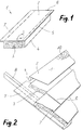
- a sub-roof panel 1 consists in essentially from a rectangular decking plate 2 to which on a long side 5, a spacer 4 is glued.
- the Cover plate consists for example of a hardboard with a thickness of 3.5mm to 5.0mm.
- the plate has a smooth side due to the manufacturing process, on which the Spacer 4 is glued and a rough side with a Grain 10, which of the roof covering, not shown here turned towards.
- the spacer 4 also consists of a fibreboard, or it is cut from such a plate, whose density is lower than that of the cover plate 2. As indicated in Figure 1, the spacer is so glued that the individual fibers essentially in are oriented at right angles ⁇ to the cover plate 2. In order to a particularly high compressive strength is achieved and the Allows the use of a relatively light and soft insulation material.
- the spacer 4 also does not extend over the entire long side 5, so that a lateral overlap area 6 is formed for the decking plate.
- the insulation layer 3, for example made of mineral wool, plant fibers, etc. in Figure 1 is only for completeness shown. This layer of insulation is not firm with the cover plate 2, but is separately provided by the customer Cuts or rolls delivered and directly when building the Posted under roof. The width of the insulation strips is dimensioned so that on the spacer 4 facing longitudinal side forms a longitudinal overlap area 7.
- the sub-roof panels 1 built in rows from the eaves to the ridge. You are lying on a view formwork 9 by the Rafters 8 is worn. After striking an insulation layer 3, this in turn is from a sub-roof panel 1 covered, with the individual plates scaly overlap. The attachment is done by mounting Counter battens with special nails or screws that go into the underlying rafters 8 are driven. On this one not shown counter battens and roof battens Roof skin consisting of bricks, sheet metal, etc. laid.
- Figures 3 and 3a show a highly schematic semi-automatic Production in which the spacer bars are already in place stacked.
- a conveyor belt or chain 11 moves in the direction of arrow a and transports individual cover plates 2 to different workstations. They pass at least one glue application station 12, an adhesive station 13, a pressing station 14 and a removal station 15. Before the glue application station 12 could be another separate feed station can be arranged.
- the decking sheets are provided as a stack 16 at the beginning of the conveyor belt.
- the individual spacer webs 4 rest as a stack 19 the gluing station 13 ready.
- a cold glue dispenser 17 a double track of cold glue 23 (FIG. 3a) on the contact surface applied.
- a hot melt adhesive dispenser 18 a middle trace of hot melt adhesive 22 is applied.
- a spacer 4 is placed on each contact surface coated with adhesive and placed exactly positioned.
- the sub-roof panels 1 from Conveyor belt 11 removed and on a stack 21 on the way described in more detail below for the final curing of the cold glue stacked.
- Figure 4 shows an alternative production option with identical workstations as in the exemplary embodiment according to Figure 3.
- the same components therefore have the same Reference numerals.
- the feed is not carried out on one Conveyor belt, but on a turntable 25, which is cycled rotates about a central axis 27.
- the adhesive dispenser 17 and 18 must therefore be moved on a feed path 26, to apply the traces of glue.
- the stack 21 is placed on suitable supports 34, so that it can be lifted later with a forklift.
- a stop frame is used on one long side as stop aids 35 and a stop side wall on one end face 36.
- the stop frame 35 can be after the finished construction Remove the stack to make strapping easier.
- the stacking is carried out in such a way that several cover plates each 2a to 2f lie flat on top of each other.
- the assigned to them Spacers 4a to 4f lie side by side and are staggered like stairs. Since the graduation in Not continued arbitrarily with regard to the stack width the stack is divided into several groups 28, 28 ' divided. Two successive groups each form a pair of groups 29. The two groups of a pair are reversed in each case, i.e. rotated by 180 °, facing each other.
- the spacers 4a to 4f of group 28 are thus directed against the first cover plate 2a of group 28 ', while the spacers 4a 'to 4f' of the reverse staggered second group 28 'against the top cover plate 2f group 28 are directed.
- a second follows Group pair 29 ', which in turn has the same structure as that first group pair 29.
- groups of Six sub-roof tiles each shown. That number, as well however, how the number of group pairs can vary depending on the application vary.
- Figure 6 shows such a web element made of sheet steel, the to achieve sufficient lateral stability Bend 31 has. Width and height of the individual sections 32 correspond to the width of the individual spacers 4 and the height difference in the graduation.
- Spacer blocks 33 inserted to deflect the decking plates to prevent.
- a power transmission for pressing purposes is not necessary here. After pressing and The web elements can also harden the adhesive connections 30 removed and replaced by spacer blocks 33 become.
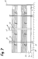
- Figure 7 shows a view of the long side of a stack 21, four web elements distributed over the entire length 30 are inserted per group pair. At two places the stack is surrounded by a strapping 39 and is compressed and stabilized by it. The strapping are not directly on the sub-roof panels, but develop their pressing force via a lower square timber 37 and an upper square timber 38. The two strapping are sufficient for the later transport of the stack. However, to at least during the curing time of the adhesive Generating sufficient contact pressure is in the middle range a releasable tensioning strap 40 is applied, which by means of a Clamping device 41 brought to a desired clamping force can be.
- the stop frame 35 has already been removed in FIG to make it easier to put on the straps and straps. After removing the strap 40, the whole Stack still be surrounded with a shrink wrap, which protects the roof tiles from moisture.
Landscapes
- Engineering & Computer Science (AREA)
- Architecture (AREA)
- Civil Engineering (AREA)
- Structural Engineering (AREA)
- Physics & Mathematics (AREA)
- Electromagnetism (AREA)
- Roof Covering Using Slabs Or Stiff Sheets (AREA)
Abstract
Description
- Fig. 1
- Eine Unterdachplatte in perspektivischer Darstellung,
- Fig. 2
- der Aufbau eines Unterdachs unter Verwendung von Unterdachplatten gemäss Fig. 1 in perspektivischer Darstellung,
- Fig. 3
- Eine Draufsicht auf eine Produktionslinie mit linearem Vorschub,
- Fig. 3a
- ein Detail des Klebstoffauftrags an der Produktionslinie gemäss Fig. 3,
- Fig. 4
- eine Draufsicht auf eine Produktionslinie mit rotierendem Vorschub,
- Fig. 5
- eine Ansicht auf die Stirnseite eines Stapels,
- Fig. 6
- ein Stegelement in perspektivischer Darstellung, und
- Fig. 7
- eine Ansicht auf die Längsseite eines Stapels.
Claims (15)
- Verfahren zum Herstellen von Unterdachplatten (1), bestehend aus je einer Deckbelagplatte (2) zum Ueberdecken einer Dämmschicht (3), an der auf einer Längsseite (5) ein Distanzsteg (4) zum Uebertragen der Dachlast auf eine Tragkonstruktion angeklebt ist, dadurch gekennzeichnet, dass die Unterdachplatten (1) nach dem Auftragen von Klebstoff auf wenigstens einer Kontaktfläche zwischen Deckbelagplatte (2) und Distanzsteg (4) gestapelt werden, wobei jeweils mehrere Deckbelagplatten (2a bis 2f) flächige aufeinanderliegen und die ihnen zugeordneten Distanzstege (4a bis 4f) gestaffelt nebeneinanderliegen und dass die endgültige Aushärtung der Klebverbindung im gestapelten Zustand erfolgt.
- Verfahren nach Anspruch 1, dadurch gekennzeichnet, dass bis zum endgültigen Aushärten der Klebverbindung ein Anpressdruck auf den ganzen Stapel ausgeübt wird.
- Verfahren nach Anspruch 1 oder 2, dadurch gekennzeichnet, dass auf die Kontaktfläche sowohl ein Kaltleim (23), als auch ein Schmelzklebstoff (22) aufgetragen wird und dass vor dem Stapeln ein Anpressdruck auf jeden Distanzsteg (4) ausgeübt wird.
- Verfahren nach Anspruch 3, dadurch gekennzeichnet, dass auf die Kontaktfläche ein mittlerer Streifen Schmelzklebstoff (22) und auf jeder Seite davon wenigstens je ein äusserer Streifen Kaltleim (23) aufgetragen wird.
- Verfahren nach Anspruch 3 oder 4, dadurch gekennzeichnet, dass der Klebstoff nur auf die Deckbelagplatte (2) aufgetragen wird.
- Verfahren nach einem der Ansprüche 3 bis 5, dadurch gekennzeichnet, dass der Klebstoffauftrag und das Anpressen der Distanzstege (4) an separaten Arbeitsstationen (12, 14) erfolgt und dass die Deckbelagplatten (2) auf einem Fördermittel (11, 25) zu den Arbeitsstationen transportiert werden.
- Verfahren nach Anspruch 2, dadurch gekennzeichnet, dass auf die Kontaktfläche ein Kaltleim aufgetragen wird und dass das Ankleben der Distanzstege (4) auf die Deckbelagplatten (2) unmittelbar beim Aufbau des Stapels (21) erfolgt.
- Verfahren nach Anspruch 7, dadurch gekennzeichnet, dass der Klebstoff nur auf die Distanzstege aufgetragen wird.
- Verfahren nach einem der Ansprüche 1 bis 8, dadurch gekennzeichnet, dass die flächig aufeinanderliegenden Deckbelagplatten (2) eines Stapels (21) jeweils eine Gruppe (28) bilden und dass ein Stapel aus mehreren Gruppen aufgebaut wird, wobei jeweils zwei Gruppen (28, 28') ein Gruppenpaar (29) bilden, bei dem die Distanzstege der einen Gruppe seitenverkehrt gegen die Deckbelagplatten der anderen Gruppe gerichtet sind.
- Verfahren nach Anspruch 9, dadurch gekennzeichnet, dass die sich an den Längsseiten des Stapels ergebenden Zwischenräume zwischen den einzelnen Gruppen mit Distanzelementen (30, 31) überbrückt werden.
- Verfahren nach Anspruch 10, dadurch gekennzeichnet, dass die Zwischenräume zwischen den freiliegenden Stirnseiten der Distanzstege einer Gruppe und der gegenüberliegenden Deckbelagplatten der benachbarten Gruppe durch Stegelemente (30) ausgefüllt werden, welche derart treppenartig ausgeschnitten sind, dass jede freiliegende Stirnseite an einem Ausschnitt (32) aufliegt.
- Verfahren nach Anspruch 11, dadurch gekennzeichnet, dass die Stegelemente (30) nach dem endgültigen Aushärten des Klebstoffs, bzw. nach dem Zusammenpressen des Stapels entfernt und durch einfache Distanzklötze (33) ersetzt werden.
- Verfahren nach einem der Ansprüche 1 bis 12, dadurch gekennzeichnet, dass jeder Stapel mittels am Stapel verbleibenden Umreifungsbändern (39) zusammengehalten und zusammengepresst wird.
- Verfahren nach einem der Ansprüche 1 bis 13, dadurch gekennzeichnet, dass jeder Stapel bis zum endgültigen Aushärten des Klebstoffs mit wenigstens einem lösbaren Zugband (40) zusammengepresst wird.
- Verfahren, insbesondere nach einem der Ansprüche 1 bis 14, dadurch gekennzeichnet, dass für die Deckbelagplatten (2) eine Holzfaserhartplatte mit einer glatten und mit einer rauhen Seite und für die Distanzstege eine Holzfaserplatte von geringerer Dichte verwendet wird, wobei die Distanzstege derart auf die glatte Seite der Deckbelagplatten geklebt werden, dass die Fasern des Distanzstegs im wesentlichen im rechten Winkel zur Deckbelagplatte verlaufen.
Priority Applications (1)
| Application Number | Priority Date | Filing Date | Title |
|---|---|---|---|
| EP97810684A EP0903447A1 (de) | 1997-09-19 | 1997-09-19 | Vefahren zum Herstellen von Unterdachplatten |
Applications Claiming Priority (1)
| Application Number | Priority Date | Filing Date | Title |
|---|---|---|---|
| EP97810684A EP0903447A1 (de) | 1997-09-19 | 1997-09-19 | Vefahren zum Herstellen von Unterdachplatten |
Publications (1)
| Publication Number | Publication Date |
|---|---|
| EP0903447A1 true EP0903447A1 (de) | 1999-03-24 |
Family
ID=8230392
Family Applications (1)
| Application Number | Title | Priority Date | Filing Date |
|---|---|---|---|
| EP97810684A Withdrawn EP0903447A1 (de) | 1997-09-19 | 1997-09-19 | Vefahren zum Herstellen von Unterdachplatten |
Country Status (1)
| Country | Link |
|---|---|
| EP (1) | EP0903447A1 (de) |
Citations (3)
| Publication number | Priority date | Publication date | Assignee | Title |
|---|---|---|---|---|
| US2664835A (en) * | 1948-08-11 | 1954-01-05 | Clarence T Sorensen | Building surfacing material |
| DE2442775A1 (de) * | 1974-09-06 | 1976-03-18 | Herbert Fiegl | Warmdachkonstruktion fuer geneigte dachflaechen |
| DE3437446A1 (de) * | 1983-10-24 | 1985-05-02 | Leganorm AG, Winterthur | Isolierelement fuer ein waerme- und schalldaemmendes unterdach |
-
1997
- 1997-09-19 EP EP97810684A patent/EP0903447A1/de not_active Withdrawn
Patent Citations (3)
| Publication number | Priority date | Publication date | Assignee | Title |
|---|---|---|---|---|
| US2664835A (en) * | 1948-08-11 | 1954-01-05 | Clarence T Sorensen | Building surfacing material |
| DE2442775A1 (de) * | 1974-09-06 | 1976-03-18 | Herbert Fiegl | Warmdachkonstruktion fuer geneigte dachflaechen |
| DE3437446A1 (de) * | 1983-10-24 | 1985-05-02 | Leganorm AG, Winterthur | Isolierelement fuer ein waerme- und schalldaemmendes unterdach |
Similar Documents
| Publication | Publication Date | Title |
|---|---|---|
| EP1007809B1 (de) | Verstärkungsvorrichtung für tragstrukturen | |
| EP0075187B1 (de) | Platte aus Dämmstoffen, insbesondere Mineralfasern | |
| EP1301669A1 (de) | Selbsttragendes und lastabtragendes bauelement | |
| EP0641901A1 (de) | Montage-Bausystem für ein Holzhaus | |
| EP0004086B1 (de) | Tafelförmiger Lamellenisolierkörper und Verfahren zu dessen Herstellung | |
| EP0593984B1 (de) | Wandbauelement sowie daraus gebildete Wand | |
| DE19922592A1 (de) | Dämmstoffelement aus Mineralwolle sowie Verfahren zu seiner Herstellung und Verwendung desselben | |
| DE3137483A1 (de) | Schalungstraeger aus holz sowie verfahren zur herstellung eines derartigen holz-schalungstraegers | |
| EP1892088B1 (de) | Verfahren zur Herstellung einer Leichtbauplatte | |
| DE102009054699A1 (de) | Verfahren zum Herstellen einer Heiztafel | |
| DE2508795A1 (de) | Verfahren und vorrichtung zur herstellung von isolierbausteinen | |
| CH660765A5 (de) | Verfahren zum einbau von in rollenform vorliegendem mineralfasermaterial zwischen stuetzen wie dachsparren, sowie zur durchfuehrung des verfahrens geeignete mineralfaserbahn. | |
| AT509322B1 (de) | Verfahren zur herstellung von plattenelementen | |
| EP0918910A1 (de) | Tragendes plattenelement aus holz für deckenkonstruktionen oder für den brückenbau sowie verwendung einer schraube zum verbinden von brettern zu einem plattenelement | |
| EP0953088B9 (de) | Tragwerk und dessen konstruktionselemente | |
| EP1253257B1 (de) | Verfahren zur Herstellung eines Flächenelementes | |
| DE3221866A1 (de) | Abstandshalter | |
| DE10101929B4 (de) | Aufsparrendämmsystem | |
| AT405845B (de) | Verfahren zur herstellung einer mineralfaserlamellenbahn und vorrichtung zur durchführung des verfahrens | |
| DE3932058A1 (de) | Verfahren zum herstellen vorgefertigter flaechen-bauelemente | |
| EP1074666A2 (de) | Verbindungselement für zumindest zum Teil aus Holz bestehende Bauelemente | |
| DE10228935C1 (de) | Anlage zur Herstellung von Holzspanplatten und dergleichen | |
| DE20209991U1 (de) | Doppelbandpresse zur Herstellung von Plattenwerkstoffen | |
| DE29605098U1 (de) | Schalenbauteil für Wände oder Decken | |
| DE19618587C2 (de) | Verfahren zum Errichten einer Unterkonstruktion und dafür geeignetes Dachausbauelement |
Legal Events
| Date | Code | Title | Description |
|---|---|---|---|
| PUAI | Public reference made under article 153(3) epc to a published international application that has entered the european phase |
Free format text: ORIGINAL CODE: 0009012 |
|
| AK | Designated contracting states |
Kind code of ref document: A1 Designated state(s): AT CH DE FI FR LI SE |
|
| AX | Request for extension of the european patent |
Free format text: AL;LT;LV;RO;SI |
|
| 17P | Request for examination filed |
Effective date: 19990902 |
|
| AKX | Designation fees paid |
Free format text: AT CH DE FI FR LI SE |
|
| RAP1 | Party data changed (applicant data changed or rights of an application transferred) |
Owner name: DIETRICH ISOLIERPLATTENFABRIK |
|
| RIN1 | Information on inventor provided before grant (corrected) |
Inventor name: DIETRICH ISOLIERPLATTENFABRIK |
|
| 17Q | First examination report despatched |
Effective date: 20030318 |
|
| STAA | Information on the status of an ep patent application or granted ep patent |
Free format text: STATUS: THE APPLICATION IS DEEMED TO BE WITHDRAWN |
|
| 18D | Application deemed to be withdrawn |
Effective date: 20030729 |