EP0902918B1 - Regeleinrichtung und -verfahren für motoren - Google Patents
Regeleinrichtung und -verfahren für motoren Download PDFInfo
- Publication number
- EP0902918B1 EP0902918B1 EP97927135A EP97927135A EP0902918B1 EP 0902918 B1 EP0902918 B1 EP 0902918B1 EP 97927135 A EP97927135 A EP 97927135A EP 97927135 A EP97927135 A EP 97927135A EP 0902918 B1 EP0902918 B1 EP 0902918B1
- Authority
- EP
- European Patent Office
- Prior art keywords
- motor
- sensor
- force
- velocity
- signal
- Prior art date
- Legal status (The legal status is an assumption and is not a legal conclusion. Google has not performed a legal analysis and makes no representation as to the accuracy of the status listed.)
- Expired - Lifetime
Links
Images
Classifications
-
- G—PHYSICS
- G05—CONTROLLING; REGULATING
- G05B—CONTROL OR REGULATING SYSTEMS IN GENERAL; FUNCTIONAL ELEMENTS OF SUCH SYSTEMS; MONITORING OR TESTING ARRANGEMENTS FOR SUCH SYSTEMS OR ELEMENTS
- G05B19/00—Program-control systems
- G05B19/02—Program-control systems electric
- G05B19/18—Numerical control [NC], i.e. automatically operating machines, in particular machine tools, e.g. in a manufacturing environment, so as to execute positioning, movement or co-ordinated operations by means of program data in numerical form
- G05B19/19—Numerical control [NC], i.e. automatically operating machines, in particular machine tools, e.g. in a manufacturing environment, so as to execute positioning, movement or co-ordinated operations by means of program data in numerical form characterised by positioning or contouring control systems, e.g. to control position from one programmed point to another or to control movement along a programmed continuous path
- G05B19/21—Numerical control [NC], i.e. automatically operating machines, in particular machine tools, e.g. in a manufacturing environment, so as to execute positioning, movement or co-ordinated operations by means of program data in numerical form characterised by positioning or contouring control systems, e.g. to control position from one programmed point to another or to control movement along a programmed continuous path using an incremental digital measuring device
- G05B19/23—Numerical control [NC], i.e. automatically operating machines, in particular machine tools, e.g. in a manufacturing environment, so as to execute positioning, movement or co-ordinated operations by means of program data in numerical form characterised by positioning or contouring control systems, e.g. to control position from one programmed point to another or to control movement along a programmed continuous path using an incremental digital measuring device for point-to-point control
- G05B19/231—Numerical control [NC], i.e. automatically operating machines, in particular machine tools, e.g. in a manufacturing environment, so as to execute positioning, movement or co-ordinated operations by means of program data in numerical form characterised by positioning or contouring control systems, e.g. to control position from one programmed point to another or to control movement along a programmed continuous path using an incremental digital measuring device for point-to-point control the positional error is used to control continuously the servomotor according to its magnitude
- G05B19/237—Numerical control [NC], i.e. automatically operating machines, in particular machine tools, e.g. in a manufacturing environment, so as to execute positioning, movement or co-ordinated operations by means of program data in numerical form characterised by positioning or contouring control systems, e.g. to control position from one programmed point to another or to control movement along a programmed continuous path using an incremental digital measuring device for point-to-point control the positional error is used to control continuously the servomotor according to its magnitude with a combination of feedback covered by G05B19/232 - G05B19/235
-
- G—PHYSICS
- G05—CONTROLLING; REGULATING
- G05B—CONTROL OR REGULATING SYSTEMS IN GENERAL; FUNCTIONAL ELEMENTS OF SUCH SYSTEMS; MONITORING OR TESTING ARRANGEMENTS FOR SUCH SYSTEMS OR ELEMENTS
- G05B2219/00—Program-control systems
- G05B2219/30—Nc systems
- G05B2219/33—Director till display
- G05B2219/33078—Error table, interpolate between two stored values to correct error
-
- G—PHYSICS
- G05—CONTROLLING; REGULATING
- G05B—CONTROL OR REGULATING SYSTEMS IN GENERAL; FUNCTIONAL ELEMENTS OF SUCH SYSTEMS; MONITORING OR TESTING ARRANGEMENTS FOR SUCH SYSTEMS OR ELEMENTS
- G05B2219/00—Program-control systems
- G05B2219/30—Nc systems
- G05B2219/37—Measurements
- G05B2219/37019—Position detection integrated in actuator, lvdt integrated linear actuator
-
- G—PHYSICS
- G05—CONTROLLING; REGULATING
- G05B—CONTROL OR REGULATING SYSTEMS IN GENERAL; FUNCTIONAL ELEMENTS OF SUCH SYSTEMS; MONITORING OR TESTING ARRANGEMENTS FOR SUCH SYSTEMS OR ELEMENTS
- G05B2219/00—Program-control systems
- G05B2219/30—Nc systems
- G05B2219/37—Measurements
- G05B2219/37035—Sensor in air gap of drive, detect directly speed or position
-
- G—PHYSICS
- G05—CONTROLLING; REGULATING
- G05B—CONTROL OR REGULATING SYSTEMS IN GENERAL; FUNCTIONAL ELEMENTS OF SUCH SYSTEMS; MONITORING OR TESTING ARRANGEMENTS FOR SUCH SYSTEMS OR ELEMENTS
- G05B2219/00—Program-control systems
- G05B2219/30—Nc systems
- G05B2219/37—Measurements
- G05B2219/37323—Derive acceleration from position or speed
-
- G—PHYSICS
- G05—CONTROLLING; REGULATING
- G05B—CONTROL OR REGULATING SYSTEMS IN GENERAL; FUNCTIONAL ELEMENTS OF SUCH SYSTEMS; MONITORING OR TESTING ARRANGEMENTS FOR SUCH SYSTEMS OR ELEMENTS
- G05B2219/00—Program-control systems
- G05B2219/30—Nc systems
- G05B2219/41—Servomotor, servo controller till figures
- G05B2219/41436—Feedforward of speed and acceleration
-
- G—PHYSICS
- G05—CONTROLLING; REGULATING
- G05B—CONTROL OR REGULATING SYSTEMS IN GENERAL; FUNCTIONAL ELEMENTS OF SUCH SYSTEMS; MONITORING OR TESTING ARRANGEMENTS FOR SUCH SYSTEMS OR ELEMENTS
- G05B2219/00—Program-control systems
- G05B2219/30—Nc systems
- G05B2219/42—Servomotor, servo controller kind till VSS
- G05B2219/42064—Position, speed and acceleration
Definitions
- the invention relates to a control device for an engine of the type mentioned in the preamble of claim 1 specified type and a method for controlling a Motors.
- Control devices for operating motors are general known, e.g. from WO-85 05 710 A1.
- Sensor determines the state of motion or the position of the motor and fed to the control device, which depends on the engine the difference between the setpoint and actual value of the motor parameters operates. This way you can also timed variable default values such as position, speed or Acceleration are observed relatively accurately.
- an automatic assembly machine must be used to assemble circuit boards a point-to-point movement with electronic components execute, on the one hand the point can be controlled very precisely for inserting the component must, on the other hand, the point-to-point movement with high Speed should take place due to the accelerations and decelerations, to vibrations in the system which in turn leads to accuracy in positioning affect.
- This also applies to modern milling machines, where a relatively small milling head for different large milling openings and contours is used. Here too must have great positional accuracy at high speed or acceleration of the milling head.
- translatory drives ball screw drives used, where an electric motor drives a ball screw, which in turn is a tool table or a workpiece table shifts.
- the motor control then takes place on the one hand via a rotary encoder on the motor and a linear scale at the tool table.
- the control accuracy can be achieved by using a so-called Feedforward control, for example with the speed controller additionally one derived from the target values Speed pilot signal is supplied, to further increase the problems outlined above the phase shift, phase shift and the However, delays remain.
- the invention is therefore based on the object of a control device for an engine to create a quick one and allows precise control of the state of motion of the engine; furthermore, a corresponding method for Regulation of an engine can be created.
- the sensor for detecting the state of motion of the engine at the power transmission point of the engine arranged. This way, all changes to the Movement state of the motor directly recorded and the controller are supplied so that an immediate regulation is possible which is essentially free of mechanical influences and / or influences of the control device such as differentiation etc. is.
- the sensor directly detects at least one state parameter of the power transmission medium at the power transmission point of the engine, for example the pressure state of a fluid or the electrical and / or magnetic field strength of a Electric motor, i.e. of the field, which is also the power transmission serves in the engine.
- This state parameter is immediate a measure of the state of movement or changes the state of motion of the engine; is for this purpose the sensor in the broadest sense "in” the power transmission medium arranged of the engine.
- the sensor can be an angular position encoder, an angular velocity encoder or an angular accelerator in the case a rotary motor or a displacement sensor, a speed sensor and / or an accelerometer in the case of a Linear motor.
- the state of motion of the engine directly at the power transmission interface determined, and advantageously via the power transmission medium.
- the control method can advantageously with a cascade control with a speed and / or Acceleration control can be combined; it is also possible a speed and / or acceleration pre-control to use.
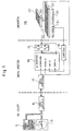
- 10 denotes a machine computer for control the CNC machine.
- the machine computer 10 communicates with a data carrier 20, for example the default data for controlling a milling head (not shown) contains. Via an interface 30 and an interface 40 the specification data is fed to a drive computer 100.
- the Drive computer controls an output stage 60 schematically linear motor 200 shown.
- the linear motor 200 comprises a primary part in a known manner (Reaction part) 210 and a secondary part (stand) 220.
- the speed detection can for example directly from the temporal Course of the magnetic field derived at the location of the sensor become.
- the sensors 250 and 240 send their signals to the drive computer 100, which is a speed control, position control or current control.
- the linear scale is separate from the linear motor in FIG. 1 shown, but it can also be located at the Power transmission interface, d. H. in the air gap between the engine parts. Also for the linear scale or the position sensor can determine the properties of the power transmission medium, d. H. of the electromagnetic field become.
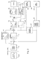
- Fig. 2 shows an example of the structure in greater detail the motor control running in the work computer 100.
- a linear position interpolator 110 From the machine computer 10 or the data carrier 20 the default data on a linear position interpolator 110 given. This data is fed to a subtraction element 111, the inverting input of the actual position data from the linear scale 230 via a high-resolution position interface 50 are supplied. Then the Difference fed to a position controller 112, its output data are fed to a further subtraction element 120. For the formation of the speed difference at known technology, the output signal of the position interface 50 differentiated in a differentiator 250 'and supplied to the subtraction member 120. The subtractor a circuit for determining the acceleration deviation closes on, namely in a circuit 270 determines the target acceleration from which the actual acceleration is subtracted by another differentiator 260 'was derived. A subsequent rule section from a current regulator 130, an output stage 60 and a Current vector generator 132 forms the drive current for the synchronous linear motor 200.
- the regulation shown thus represents a cascaded regulation represents, in addition a speed feedforward control 122 can be made in addition a speed pilot signal to the subtractor 120 is given.
- the inventive control scheme deviates from from the control scheme shown above in that instead of of the differentiating element 250 'is an additional sensor 250 is provided directly on or in the synchronous linear motor. This Sensor 250 immediately determines the speed of the primary part of the engine and directs a corresponding one Signal to subtractor 120.
- a separate acceleration sensor can also be used for acceleration measurement 260 should be provided, without differentiation the acceleration signal to the subtractor 272 outputs, so that the differentiator 260 'is dispensed with can be.
- the differentiators 250 ', 260' by appropriate sensors 250, 260, which directly record the state of motion of the motor, replaced.
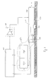
- the speed sensor 250 a coil sensor located near the Air gap of the linear motor 200 is arranged and that electromagnetic field detected in the air gap. That means, that the sensor detects the electromagnetic field directly, on which the power transmission of the engine is based.
- the coils of the sensor 250 are subjected to electrical voltages induced that is proportional to the temporal change in the magnetic field and therefore proportional (with a stationary magnetic field) to speed.
- the (analog) signal of the Coil sensor 250 will be described later Signal processing in a converter 252, if necessary after quantization, as a speed signal v to the drive computer 100 fed.
- the signal from the coil sensor 250 is furthermore an acceleration proportional to the differentiator 260 'already explained Signal a derived and also fed to the drive computer 100.
- About the amplifier or the output stage 60 is controlled by the drive computer 100 Movement of the secondary part 210 of the linear motor 200.
- the exemplary embodiment according to FIG. 3 has the decisive one Advantage that directly a speed proportional Signal from sensor 250 is emitted. This eliminates the Need from an already discrete position signal derive another quantized speed signal.
- this embodiment also with regard to the acceleration control decisive advantages.
- acceleration only by simply differentiating the speed signal preserved and not as with the stand the technology, by twofold differentiation of a position signal.
- the second is the speed sensor 250 arranged directly at the force interface, and that acceleration signal derived from the speed signal a therefore corresponds directly to the differential acceleration between the primary part 210 and the secondary part 220.
- a double acceleration measurement, on the one hand on the primary part 220, on the other hand on the secondary part 210, with subsequent Difference formation to determine the actual Differential acceleration is not required.
- the signal converter 252 already mentioned is provided for processing the signal from the sensor 250, the function of which is explained below.
- the coil sensor 250 is arranged directly at the force interface of the motor 200, ie it runs on the same magnetic track as the primary part 210.
- the signal of the speed sensor 250 in the signal converter 252 is advantageously first rectified, and the signal of the travel sensor 240 is additionally fed to the speed converter.
- the speed data of the sensor 250 and the position data of the displacement sensor 240 are simultaneously recorded and correlated with one another, so that the position-dependent position of the speed signal can be determined at a constant speed of the secondary part 210.
- a correction function v * ( s ) is then determined in a known manner from the location-dependent function v ( s ) of the speed signal, which indicates how the signal of the sensor 250 must be corrected in order to determine a speed signal that is constant at all locations .
- the value pairs s i , v * i , for each location point can then be stored, for example, in a look-up table in the signal converter 252, so that the corresponding correction value v * i and the signal of the speed sensor 250 can be called up for each location point s i can be corrected accordingly in an evaluation logic (not shown).
- the signal converter 252, the differentiator 260 'and the sensor 250 can be combined to form a unit, as indicated by the broken line 254 in FIG. 3.
- This unit 254 is then integrated directly into the primary part 210 of the motor 200, so that the motor 200 only has connections for the position signal s , the speed signal v and the acceleration signal a to the outside.
- the correction function can, for example, be updated automatically at regular intervals or always at the start of operation in order to take gradual changes, for example due to wear, into account.
Landscapes
- Engineering & Computer Science (AREA)
- Human Computer Interaction (AREA)
- Manufacturing & Machinery (AREA)
- Physics & Mathematics (AREA)
- General Physics & Mathematics (AREA)
- Automation & Control Theory (AREA)
- Control Of Linear Motors (AREA)
- Control Of Electric Motors In General (AREA)
- Control Of Position Or Direction (AREA)
Description
- Fig. 1
- eine schematische Darstellung einer CNC-gesteuerten Werkzeugmaschine mit einem Linearmotor,
- Fig. 2
- eine schematisch Darstellung eines erfindungsgemäßen Reglers, und
- Fig. 3
- eine weitere schematische Darstellung einer CNC-Maschine mit Linearmotor.
Claims (22)
- Regeleinrichtung für einen Motor (200), wobei der Motor (200) zumindest zwei Motorteile (210, 220) aufweist, die über eine Kraftübertragungsschnittstelle (270) miteinander wechselwirken und relativ zueinander bewegbar sind, einem Sensor (250) zur Erfassung des Bewegungszustandes der Motorteile und einem Regler (100) zur Regelung des Bewegungszustandes des Motors abhängig von Signalen des Sensors, dadurch gekennzeichnet, daß der Sensor der Kraftübertragungsschnittstelle (270) des Motors (200) zugeordnet ist und zumindest einen Zustandsparameter des Kraftübertragungsmediums des Motors erfaßt.
- Regeleinrichtung nach Anspruch 1, dadurch gekennzeichnet, daß der Sensor im Kraftübertragungsmedium des Motors angeordnet ist.
- Regeleinrichtung nach Anspruch 1 oder 2, dadurch gekennzeichnet, daß das Kraftübertragungsmedium des Motors ein Fluid oder ein elektromagnetisches Feld ist.
- Regeleinrichtung nach einem der Ansprüche 1 bis 3, dadurch gekennzeichnet, daß der Motor ein Rotationsmotor ist und der Sensor ein Winkellagengeber, ein Winkelgeschwindigkeitsgeber und/oder ein Winkelbeschleunigungsgeber ist.
- Regeleinrichtung nach einem der Ansprüche 1 bis 4, dadurch gekennzeichnet, daß der Motor ein Linearmotor ist und der Sensor ein Weggeber, ein Geschwindigkeitsgeber und/oder ein Beschleunigungsgeber ist.
- Regeleinrichtung nach einem der Ansprüche 4 oder 5, dadurch gekennzeichnet, daß der Sensor das elektromagnetische Feld oder Änderungen des elektromagnetischen Feldes erfaßt, auf das sich die Kraftübertragung des Motors stützt.
- Regeleinrichtung nach Anspruch 6, dadurch gekennzeichnet, daß der Sensor (250) ein Induktionssensor ist.
- Regeleinrichtung nach Anspruch 7, dadurch gekennzeichnet, daß der Sensor (250) eine oder mehrere Spulen aufweist.
- Regeleinrichtung nach einem der vorstehenden Ansprüche, gekennzeichnet durch einen Signalumsetzer (252), der mit einem Weggeber (240) und mit dem Sensor (250) zur Erfassung des Bewegungszustandes verbunden ist und Speicher- und Korrekturmittel aufweist, um eine mögliche Abhängigkeit des Signals des Sensors (250) von der Position zu kompensieren.
- Verfahren zur Regelung eines Motors, wobei der Motor zumindest zwei Motorteile aufweist, die über eine Kraftübertragungsschnittstelle miteinander wechselwirken und relativ zueinander bewegbar sind, dadurch gekennzeichnet, daß man den Bewegungszustand des Motors an der Kraftübertragungsschnittstelle des Motors durch Zustandsparameter des Kraftübertragungsmediums des Motors erfaßt.
- Verfahren nach Anspruch 10, dadurch gekennzeichnet, daß man den Druck eines Fluids oder Druckänderungen oder die Stärke eines elektromagnetischen Feldes oder Feldänderungen an der Kraftübertragungsschnittstelle des Motors erfaßt.
- Verfahren nach einem der Ansprüche 10 oder 11, dadurch gekennzeichnet, daß man die Winkellage der Motorteile, die Winkelgeschwindigkeit und/oder die Winkelbeschleunigung an der Kraftübertragungsschnittstelle erfaßt.
- Verfahren nach einem der Ansprüche 10 bis 12, dadurch gekennzeichnet, daß man einen linearen Weg, eine Lineargeschwindigkeit und/oder eine Linearbeschleunigung an der Kraftübertragungsschnittstelle des Motors erfaßt.
- Verfahren nach einem der Ansprüche 10 bis 13, dadurch gekennzeichnet, daß eine Lagenregelung und eine Geschwindigkeitsregelung kaskadiert sind.
- Verfahren nach Anspruch 14, dadurch gekennzeichnet, daß man eine Geschwindigkeitsvorsteuerung vornimmt.
- Verfahren nach Anspruch 14 oder 15, dadurch gekennzeichnet, daß man eine kaskadierte Regelung mit einer Beschleunigungsregelung vornimmt.
- Verfahren nach Anspruch 16, dadurch gekennzeichnet, daß man eine Beschleunigungsvorsteuerung vornimmt.
- Verfahren nach einem der Ansprüche 10 bis 17, dadurch gekennzeichnet, daß man den Bewegungszustand des Motors mit einem Induktionssensor, vorzugsweise einem Sensor (250) mit einer oder mehreren Spulen, an der Kraftübertragungsschnittstelle eines Elektromotors in Form eines geschwindigkeitsproportionalen Signals erfaßt.
- Verfahren nach Anspruch 18, dadurch gekennzeichnet, daß das geschwindigkeitsproportionale Signal einer Geschwindigkeitsregelung zugeführt wird und daß das geschwindigkeitsproportionale Signal nach zeitlicher Differenzierung einer Beschleunigungsregelung zugeführt wird.
- Verfahren nach einem der Ansprüche 18 oder 19, dadurch gekennzeichnet, daß man vor Inbetriebnahme des Motors in einem Testablauf den Motor ein oder mehrere Male mit konstanter Geschwindigkeit betreibt und das geschwindigkeitsproportionale Signal in Abhängigkeit von der momentanen Position des Motors aufnimmt,daß man aus dem momentanen geschwindigkeitsproportionalen Signal (v) und den Signalen über den momentanen Ort (s) eine Korrekturfunktion (v*(s)) ermittelt unddaß man das Signal des Sensors (250) mittels der Korrekturfunktion derart kompensiert, daß Abhängigkeiten der Signale des Sensors (250) von der Position (s) des Motors ausgeglichen werden.
- Verfahren nach Anspruch 20, dadurch gekennzeichnet, daß die Korrekturfunktion (v*(s)) in Form einer Nachschlagtabelle abgespeichert oder in Form einer Näherungsfunktion generiert wird.
- Verwendung einer Regeleinrichtung nach einem der Ansprüche 1 bis 9 oder eines Regelverfahrens nach einem der Ansprüche 10 bis 21, bei einem Translationsantrieb einer Werkzeugmaschine, eines Bestückungsautomaten, eines Bondingautomaten oder dergleichen.
Applications Claiming Priority (3)
| Application Number | Priority Date | Filing Date | Title |
|---|---|---|---|
| DE19622699 | 1996-06-05 | ||
| DE19622699A DE19622699A1 (de) | 1996-06-05 | 1996-06-05 | Regeleinrichtung und -verfahren für Motoren |
| PCT/EP1997/002910 WO1997046924A1 (de) | 1996-06-05 | 1997-06-05 | Regeleinrichtung und -verfahren für motoren |
Publications (3)
| Publication Number | Publication Date |
|---|---|
| EP0902918A1 EP0902918A1 (de) | 1999-03-24 |
| EP0902918B1 true EP0902918B1 (de) | 2000-09-06 |
| EP0902918B2 EP0902918B2 (de) | 2005-01-12 |
Family
ID=7796291
Family Applications (1)
| Application Number | Title | Priority Date | Filing Date |
|---|---|---|---|
| EP97927135A Expired - Lifetime EP0902918B2 (de) | 1996-06-05 | 1997-06-05 | Regeleinrichtung und -verfahren für motoren |
Country Status (6)
| Country | Link |
|---|---|
| US (1) | US6118245A (de) |
| EP (1) | EP0902918B2 (de) |
| JP (1) | JP2000512478A (de) |
| KR (1) | KR20000016377A (de) |
| DE (2) | DE19622699A1 (de) |
| WO (1) | WO1997046924A1 (de) |
Cited By (3)
| Publication number | Priority date | Publication date | Assignee | Title |
|---|---|---|---|---|
| DE10342562A1 (de) * | 2003-09-15 | 2005-04-21 | Siemens Ag | Regelungseinrichtung bzw. Regelung einer elektrischen Maschine |
| DE10243217B4 (de) * | 2001-09-17 | 2009-06-10 | Ford Motor Co., Dearborn | Verfahren und Vorrichtung zur Entmagnetisierungskompensation für einen Elektromotor |
| CN107742997A (zh) * | 2017-10-20 | 2018-02-27 | 北京航天发射技术研究所 | 双轴转位机构控制系统、控制方法及捷联惯组自标定方法 |
Families Citing this family (17)
| Publication number | Priority date | Publication date | Assignee | Title |
|---|---|---|---|---|
| JP2000191140A (ja) * | 1998-12-26 | 2000-07-11 | Minebea Co Ltd | リニアモ―タを用いた搬送システム |
| DE19930777A1 (de) * | 1999-07-03 | 2001-01-04 | Heidenhain Gmbh Dr Johannes | Regelungsanordnung und Verfahren zur schnellen Lageregelung eines Elektromotors |
| DE19952805C5 (de) * | 1999-11-02 | 2011-03-31 | Thielenhaus Technologies Gmbh | Verfahren und Vorrichtung zur Finishbearbeitung von Werkstücken |
| US20020099473A1 (en) * | 2000-11-08 | 2002-07-25 | Paul Amadeo | Integrated computer-aided design (CAD) and robotic systems for rapid prototyping and manufacture of smart cards |
| JP3592628B2 (ja) * | 2000-12-06 | 2004-11-24 | 恒彦 山崎 | 数値制御方法 |
| DE20114750U1 (de) | 2001-09-06 | 2002-11-28 | Brückner Maschinenbau GmbH, 83313 Siegsdorf | Anordnung zum Betrieb einer Kontaktwalze |
| DE10304970B4 (de) * | 2003-02-06 | 2006-08-10 | Ina - Drives & Mechatronics Gmbh & Co. Ohg | Positioniereinheit mit einem Kraftsensor |
| DE10334736A1 (de) * | 2003-07-29 | 2005-02-17 | Rexroth Indramat Gmbh | Linearmotor mit Fortbewegungsregelung |
| WO2005027322A2 (de) * | 2003-09-15 | 2005-03-24 | Siemens Aktiengesellschaft | Verfahren und regelung einer elektrischen maschine bzw. vorrichtung zu deren regelung |
| DE102006015065A1 (de) * | 2006-03-31 | 2007-10-18 | Siemens Ag | Einbaumotor, insbesondere Einbau-Torquemotor |
| US8084969B2 (en) * | 2007-10-01 | 2011-12-27 | Allegro Microsystems, Inc. | Hall-effect based linear motor controller |
| US7936144B2 (en) | 2008-03-06 | 2011-05-03 | Allegro Microsystems, Inc. | Self-calibration algorithms in a small motor driver IC with an integrated position sensor |
| EP2161826B1 (de) * | 2008-09-09 | 2011-03-16 | Siemens Aktiengesellschaft | Transfervorrichtung mit dynamisch veränderbaren Antriebsbereichen |
| EP2574820B1 (de) | 2011-09-30 | 2014-04-16 | Siemens Aktiengesellschaft | Bearbeitungsmaschine mit Schwingungskompensation beweglicher mechanischer Strukturen |
| EP2574821B1 (de) | 2011-09-30 | 2013-10-30 | Siemens Aktiengesellschaft | Aktiver Schwingungsdämpfer ohne direkte Beschleunigungserfassung |
| DE102012210097A1 (de) * | 2012-06-15 | 2013-12-19 | Hilti Aktiengesellschaft | Steuerungsverfahren |
| CN104793568A (zh) * | 2015-04-10 | 2015-07-22 | 深圳市明速自动化设备有限公司 | 多轴插补方法 |
Family Cites Families (23)
| Publication number | Priority date | Publication date | Assignee | Title |
|---|---|---|---|---|
| US2020780A (en) † | 1934-05-11 | 1935-11-12 | Jennie B Hamilton | Price tag support |
| US3555254A (en) * | 1967-04-17 | 1971-01-12 | Gerber Scientific Instr Co | Error correcting system and method for use with plotters, machine tools and the like |
| DE2020780A1 (de) † | 1969-04-04 | 1970-12-17 | Pioneer Electronic Corp | Elektrischer Gleichstrommotor |
| DE2146499C3 (de) * | 1971-09-17 | 1975-09-25 | Messerschmitt-Boelkow-Blohm Gmbh, 8000 Muenchen | Regelanordnung zur abstandshaltenden elektromagnetischen Schwebeführung eines Schwebefahrzeuges gegenüber Trag- und Führungsschienen |
| US3867656A (en) † | 1971-12-13 | 1975-02-18 | Siwa Seikosha Kk | Brushless direct current motor |
| DE2314257C2 (de) † | 1973-03-22 | 1982-10-21 | Papst-Motoren GmbH & Co KG, 7742 St Georgen | Schaltungsanordnung zur Drehzahlregelung eines kollektorlosen Gleichstrommotors |
| JPS534883B2 (de) * | 1973-03-31 | 1978-02-22 | ||
| DE2414721C3 (de) * | 1974-03-27 | 1980-06-19 | Brown, Boveri & Cie Ag, 6800 Mannheim | Verfahren zur Steuerung der Drehzahl- bzw. Geschwindigkeit einer frequenzumrichtergespeisten Drehstrom-Asynchronmaschine |
| GB1596681A (en) * | 1977-01-19 | 1981-08-26 | Sony Corp | Drive circuits with speed control for brushless dc motors |
| JPS54139016A (en) * | 1978-04-20 | 1979-10-29 | Pioneer Electronic Corp | Linear motor drive controller |
| DE3148007A1 (de) * | 1981-12-04 | 1983-06-09 | Herbert Prof. Dr.-Ing. 3300 Braunschweig Weh | "pollageerfassung durch die kombination von zwei sensor-anordnungen" |
| DE3231966A1 (de) † | 1982-08-27 | 1984-03-01 | Erich 8500 Nürnberg Rabe | Elektrische maschine |
| US4628499A (en) * | 1984-06-01 | 1986-12-09 | Scientific-Atlanta, Inc. | Linear servoactuator with integrated transformer position sensor |
| DE3526166C2 (de) † | 1984-07-23 | 1996-05-02 | Asahi Chemical Ind | Bürstenloser Elektromotor und Verfahren zum Herstellen einer Spuleneinheit für diesen |
| JPH02297611A (ja) * | 1989-05-12 | 1990-12-10 | Fanuc Ltd | 速度・加速度のフィードフォアードを含むスライディングモード制御方式 |
| US5063335A (en) * | 1990-09-11 | 1991-11-05 | Allen-Bradley Company, Inc. | Two-input control with independent proportional and integral gains for velocity error and velocity feedforward including velocity command limiting |
| DE4122769A1 (de) * | 1991-07-10 | 1993-01-21 | Ief Werner Gmbh | Positionssensor fuer linearmotoren |
| JPH0683403A (ja) * | 1992-07-17 | 1994-03-25 | Fanuc Ltd | 適応pi制御方式 |
| US5250880A (en) * | 1992-10-22 | 1993-10-05 | Ford Motor Company | Linear motor control system and method |
| US5880586A (en) * | 1994-11-22 | 1999-03-09 | Robert Bosch Gmbh | Apparatus for determining rotational position of a rotatable element without contacting it |
| US5606236A (en) * | 1995-01-17 | 1997-02-25 | Eaton Corporation | Two wire position sense and control of modulating gas valve or other electromechanical actuators |
| GB2305518B (en) * | 1995-09-26 | 1999-11-03 | Custom Dev Ltd | Electronic actuator position control |
| DE19605413A1 (de) * | 1996-02-14 | 1996-07-11 | Schinkoethe Wolfgang Prof Dr I | Gleichstromlinearmotor mit integriertem Wegmeßsystem |
-
1996
- 1996-06-05 DE DE19622699A patent/DE19622699A1/de not_active Withdrawn
-
1997
- 1997-06-05 WO PCT/EP1997/002910 patent/WO1997046924A1/de not_active Ceased
- 1997-06-05 JP JP10500232A patent/JP2000512478A/ja active Pending
- 1997-06-05 DE DE59702321T patent/DE59702321D1/de not_active Expired - Lifetime
- 1997-06-05 EP EP97927135A patent/EP0902918B2/de not_active Expired - Lifetime
- 1997-06-05 US US09/194,757 patent/US6118245A/en not_active Expired - Lifetime
- 1997-06-05 KR KR1019980709951A patent/KR20000016377A/ko not_active Withdrawn
Cited By (4)
| Publication number | Priority date | Publication date | Assignee | Title |
|---|---|---|---|---|
| DE10243217B4 (de) * | 2001-09-17 | 2009-06-10 | Ford Motor Co., Dearborn | Verfahren und Vorrichtung zur Entmagnetisierungskompensation für einen Elektromotor |
| DE10342562A1 (de) * | 2003-09-15 | 2005-04-21 | Siemens Ag | Regelungseinrichtung bzw. Regelung einer elektrischen Maschine |
| US7378809B2 (en) | 2003-09-15 | 2008-05-27 | Siemens Aktiengesellschaft | Controller for controlling an electric machine |
| CN107742997A (zh) * | 2017-10-20 | 2018-02-27 | 北京航天发射技术研究所 | 双轴转位机构控制系统、控制方法及捷联惯组自标定方法 |
Also Published As
| Publication number | Publication date |
|---|---|
| WO1997046924A1 (de) | 1997-12-11 |
| KR20000016377A (ko) | 2000-03-25 |
| EP0902918B2 (de) | 2005-01-12 |
| DE19622699A1 (de) | 1997-12-11 |
| DE59702321D1 (de) | 2000-10-12 |
| JP2000512478A (ja) | 2000-09-19 |
| US6118245A (en) | 2000-09-12 |
| EP0902918A1 (de) | 1999-03-24 |
Similar Documents
| Publication | Publication Date | Title |
|---|---|---|
| EP0902918B1 (de) | Regeleinrichtung und -verfahren für motoren | |
| EP1826533B1 (de) | Magnetischer Sensor | |
| EP2048556B1 (de) | Verfahren zur Ermittlung von Kenngrössen einer angetriebenen nicht horizontal ausgerichteten Achse, insbesondere einer Werkzeugmaschine, sowie geeignete Anwendungen, korrespondierende Vorrichtungen und deren Verwendung | |
| DE3312526A1 (de) | Positioniereinrichtung mit hydraulischem stellglied | |
| EP2023092B1 (de) | Positionsmessgerät und Verfahren zur Übertragung einer Bewegungsinformation | |
| DE102014109469A1 (de) | Motor-Steuerungs-Vorrichtung | |
| EP2686952B1 (de) | Verfahren und vorrichtung zur adaption einer kommutierung für eine elektronisch kommutierte elektrische maschine | |
| EP0544108A1 (de) | Semiaktives Fahrwerksregelungssystem für Kraftfahrzeuge | |
| WO2000060220A1 (de) | Verfahren zum bestimmen der position eines ankers | |
| EP0979411B1 (de) | Anordnung zur drehzahlerfassung | |
| EP0203370A1 (de) | Schraubvorrichtung mit motorgetriebenem Schraubendreher | |
| EP0585655B1 (de) | Vorrichtung und Verfahren zur Lageregelung eines beweglichen Teils | |
| EP1939704B1 (de) | Verfahren und Vorrichtung zur Schätzung des Lastenmoments bei drehzahl- oder positionsgeregelten elektrischen Antrieben | |
| DE19708894A1 (de) | Verfahren zur Lage- und/oder Geschwindigkeitsregelung von Achsen an einer Werkzeugmaschine sowie Vorrichtung zur Durchführung eines solchen Verfahrens | |
| EP1818744A1 (de) | Reglerstruktur mit einem Torsionsmodell | |
| DE102007062738A1 (de) | Gesamtantrieb aus mehreren mechanisch zusammen gekoppelten Antrieben und Regelung für diesen Mehrfachantrieb | |
| EP0381784B1 (de) | Elektrohydraulisches Antriebssystem | |
| DE102017221562A1 (de) | Steuereinrichtung für einen Servomotor, Verfahren zum Steuern eines Servomotors und Computerprogramm | |
| DE10135540A1 (de) | Meßvorrichtung und Verfahren zur Regelung von Elektromotoren | |
| EP3235677B1 (de) | Verfahren zur lagegeberlosen regelung eines elektroantriebs | |
| EP0894292B1 (de) | Elektronische steuerung für ein steuersystem für ein getriebe | |
| DE19634279A1 (de) | Verfahren und Einrichtung zur beschleunigten Ausführung eines Programmes durch eine speicherprogrammierbare Steuerung | |
| DD239057A1 (de) | Regleranordnung zur positionierung schwach gedaempfter mechanischer regelstrecken von mehrmassensystemen | |
| DE2900019C2 (de) | ||
| DE10139932B4 (de) | Verfahren und Einrichtung zur positionsabhängigen Ereignisauslösung |
Legal Events
| Date | Code | Title | Description |
|---|---|---|---|
| PUAI | Public reference made under article 153(3) epc to a published international application that has entered the european phase |
Free format text: ORIGINAL CODE: 0009012 |
|
| 17P | Request for examination filed |
Effective date: 19990105 |
|
| AK | Designated contracting states |
Kind code of ref document: A1 Designated state(s): DE GB IT |
|
| GRAG | Despatch of communication of intention to grant |
Free format text: ORIGINAL CODE: EPIDOS AGRA |
|
| 17Q | First examination report despatched |
Effective date: 19990805 |
|
| GRAG | Despatch of communication of intention to grant |
Free format text: ORIGINAL CODE: EPIDOS AGRA |
|
| GRAH | Despatch of communication of intention to grant a patent |
Free format text: ORIGINAL CODE: EPIDOS IGRA |
|
| RAP1 | Party data changed (applicant data changed or rights of an application transferred) |
Owner name: SIEMENS LINEAR MOTOR SYSTEMS GMBH & CO. KG |
|
| GRAH | Despatch of communication of intention to grant a patent |
Free format text: ORIGINAL CODE: EPIDOS IGRA |
|
| GRAA | (expected) grant |
Free format text: ORIGINAL CODE: 0009210 |
|
| AK | Designated contracting states |
Kind code of ref document: B1 Designated state(s): DE GB IT |
|
| REF | Corresponds to: |
Ref document number: 59702321 Country of ref document: DE Date of ref document: 20001012 |
|
| ITF | It: translation for a ep patent filed | ||
| GBT | Gb: translation of ep patent filed (gb section 77(6)(a)/1977) |
Effective date: 20001109 |
|
| EN | Fr: translation not filed | ||
| PLBQ | Unpublished change to opponent data |
Free format text: ORIGINAL CODE: EPIDOS OPPO |
|
| PLBI | Opposition filed |
Free format text: ORIGINAL CODE: 0009260 |
|
| PLBF | Reply of patent proprietor to notice(s) of opposition |
Free format text: ORIGINAL CODE: EPIDOS OBSO |
|
| 26 | Opposition filed |
Opponent name: EBM WERKE GMBH & CO. Effective date: 20010602 |
|
| PLBF | Reply of patent proprietor to notice(s) of opposition |
Free format text: ORIGINAL CODE: EPIDOS OBSO |
|
| REG | Reference to a national code |
Ref country code: GB Ref legal event code: IF02 |
|
| PLBF | Reply of patent proprietor to notice(s) of opposition |
Free format text: ORIGINAL CODE: EPIDOS OBSO |
|
| REG | Reference to a national code |
Ref country code: GB Ref legal event code: 732E |
|
| PLAY | Examination report in opposition despatched + time limit |
Free format text: ORIGINAL CODE: EPIDOSNORE2 |
|
| PLBC | Reply to examination report in opposition received |
Free format text: ORIGINAL CODE: EPIDOSNORE3 |
|
| PUAH | Patent maintained in amended form |
Free format text: ORIGINAL CODE: 0009272 |
|
| STAA | Information on the status of an ep patent application or granted ep patent |
Free format text: STATUS: PATENT MAINTAINED AS AMENDED |
|
| 27A | Patent maintained in amended form |
Effective date: 20050112 |
|
| AK | Designated contracting states |
Kind code of ref document: B2 Designated state(s): DE GB IT |
|
| GBTA | Gb: translation of amended ep patent filed (gb section 77(6)(b)/1977) | ||
| PG25 | Lapsed in a contracting state [announced via postgrant information from national office to epo] |
Ref country code: IT Free format text: LAPSE BECAUSE OF NON-PAYMENT OF DUE FEES Effective date: 20050605 |
|
| REG | Reference to a national code |
Ref country code: DE Ref legal event code: R084 Ref document number: 59702321 Country of ref document: DE |
|
| PGFP | Annual fee paid to national office [announced via postgrant information from national office to epo] |
Ref country code: GB Payment date: 20110613 Year of fee payment: 15 |
|
| PGFP | Annual fee paid to national office [announced via postgrant information from national office to epo] |
Ref country code: DE Payment date: 20120820 Year of fee payment: 16 |
|
| GBPC | Gb: european patent ceased through non-payment of renewal fee |
Effective date: 20120605 |
|
| PG25 | Lapsed in a contracting state [announced via postgrant information from national office to epo] |
Ref country code: GB Free format text: LAPSE BECAUSE OF NON-PAYMENT OF DUE FEES Effective date: 20120605 |
|
| REG | Reference to a national code |
Ref country code: DE Ref legal event code: R119 Ref document number: 59702321 Country of ref document: DE Effective date: 20140101 |
|
| PG25 | Lapsed in a contracting state [announced via postgrant information from national office to epo] |
Ref country code: DE Free format text: LAPSE BECAUSE OF NON-PAYMENT OF DUE FEES Effective date: 20140101 |