EP0902918B1 - Motor-regulating device and method - Google Patents
Motor-regulating device and method Download PDFInfo
- Publication number
- EP0902918B1 EP0902918B1 EP97927135A EP97927135A EP0902918B1 EP 0902918 B1 EP0902918 B1 EP 0902918B1 EP 97927135 A EP97927135 A EP 97927135A EP 97927135 A EP97927135 A EP 97927135A EP 0902918 B1 EP0902918 B1 EP 0902918B1
- Authority
- EP
- European Patent Office
- Prior art keywords
- motor
- sensor
- force
- velocity
- signal
- Prior art date
- Legal status (The legal status is an assumption and is not a legal conclusion. Google has not performed a legal analysis and makes no representation as to the accuracy of the status listed.)
- Expired - Lifetime
Links
Images
Classifications
-
- G—PHYSICS
- G05—CONTROLLING; REGULATING
- G05B—CONTROL OR REGULATING SYSTEMS IN GENERAL; FUNCTIONAL ELEMENTS OF SUCH SYSTEMS; MONITORING OR TESTING ARRANGEMENTS FOR SUCH SYSTEMS OR ELEMENTS
- G05B19/00—Program-control systems
- G05B19/02—Program-control systems electric
- G05B19/18—Numerical control [NC], i.e. automatically operating machines, in particular machine tools, e.g. in a manufacturing environment, so as to execute positioning, movement or co-ordinated operations by means of program data in numerical form
- G05B19/19—Numerical control [NC], i.e. automatically operating machines, in particular machine tools, e.g. in a manufacturing environment, so as to execute positioning, movement or co-ordinated operations by means of program data in numerical form characterised by positioning or contouring control systems, e.g. to control position from one programmed point to another or to control movement along a programmed continuous path
- G05B19/21—Numerical control [NC], i.e. automatically operating machines, in particular machine tools, e.g. in a manufacturing environment, so as to execute positioning, movement or co-ordinated operations by means of program data in numerical form characterised by positioning or contouring control systems, e.g. to control position from one programmed point to another or to control movement along a programmed continuous path using an incremental digital measuring device
- G05B19/23—Numerical control [NC], i.e. automatically operating machines, in particular machine tools, e.g. in a manufacturing environment, so as to execute positioning, movement or co-ordinated operations by means of program data in numerical form characterised by positioning or contouring control systems, e.g. to control position from one programmed point to another or to control movement along a programmed continuous path using an incremental digital measuring device for point-to-point control
-
- G—PHYSICS
- G05—CONTROLLING; REGULATING
- G05B—CONTROL OR REGULATING SYSTEMS IN GENERAL; FUNCTIONAL ELEMENTS OF SUCH SYSTEMS; MONITORING OR TESTING ARRANGEMENTS FOR SUCH SYSTEMS OR ELEMENTS
- G05B19/00—Program-control systems
- G05B19/02—Program-control systems electric
- G05B19/18—Numerical control [NC], i.e. automatically operating machines, in particular machine tools, e.g. in a manufacturing environment, so as to execute positioning, movement or co-ordinated operations by means of program data in numerical form
- G05B19/19—Numerical control [NC], i.e. automatically operating machines, in particular machine tools, e.g. in a manufacturing environment, so as to execute positioning, movement or co-ordinated operations by means of program data in numerical form characterised by positioning or contouring control systems, e.g. to control position from one programmed point to another or to control movement along a programmed continuous path
- G05B19/21—Numerical control [NC], i.e. automatically operating machines, in particular machine tools, e.g. in a manufacturing environment, so as to execute positioning, movement or co-ordinated operations by means of program data in numerical form characterised by positioning or contouring control systems, e.g. to control position from one programmed point to another or to control movement along a programmed continuous path using an incremental digital measuring device
- G05B19/23—Numerical control [NC], i.e. automatically operating machines, in particular machine tools, e.g. in a manufacturing environment, so as to execute positioning, movement or co-ordinated operations by means of program data in numerical form characterised by positioning or contouring control systems, e.g. to control position from one programmed point to another or to control movement along a programmed continuous path using an incremental digital measuring device for point-to-point control
- G05B19/231—Numerical control [NC], i.e. automatically operating machines, in particular machine tools, e.g. in a manufacturing environment, so as to execute positioning, movement or co-ordinated operations by means of program data in numerical form characterised by positioning or contouring control systems, e.g. to control position from one programmed point to another or to control movement along a programmed continuous path using an incremental digital measuring device for point-to-point control the positional error is used to control continuously the servomotor according to its magnitude
- G05B19/237—Numerical control [NC], i.e. automatically operating machines, in particular machine tools, e.g. in a manufacturing environment, so as to execute positioning, movement or co-ordinated operations by means of program data in numerical form characterised by positioning or contouring control systems, e.g. to control position from one programmed point to another or to control movement along a programmed continuous path using an incremental digital measuring device for point-to-point control the positional error is used to control continuously the servomotor according to its magnitude with a combination of feedback covered by G05B19/232 - G05B19/235
-
- G—PHYSICS
- G05—CONTROLLING; REGULATING
- G05B—CONTROL OR REGULATING SYSTEMS IN GENERAL; FUNCTIONAL ELEMENTS OF SUCH SYSTEMS; MONITORING OR TESTING ARRANGEMENTS FOR SUCH SYSTEMS OR ELEMENTS
- G05B2219/00—Program-control systems
- G05B2219/30—Nc systems
- G05B2219/33—Director till display
- G05B2219/33078—Error table, interpolate between two stored values to correct error
-
- G—PHYSICS
- G05—CONTROLLING; REGULATING
- G05B—CONTROL OR REGULATING SYSTEMS IN GENERAL; FUNCTIONAL ELEMENTS OF SUCH SYSTEMS; MONITORING OR TESTING ARRANGEMENTS FOR SUCH SYSTEMS OR ELEMENTS
- G05B2219/00—Program-control systems
- G05B2219/30—Nc systems
- G05B2219/37—Measurements
- G05B2219/37019—Position detection integrated in actuator, lvdt integrated linear actuator
-
- G—PHYSICS
- G05—CONTROLLING; REGULATING
- G05B—CONTROL OR REGULATING SYSTEMS IN GENERAL; FUNCTIONAL ELEMENTS OF SUCH SYSTEMS; MONITORING OR TESTING ARRANGEMENTS FOR SUCH SYSTEMS OR ELEMENTS
- G05B2219/00—Program-control systems
- G05B2219/30—Nc systems
- G05B2219/37—Measurements
- G05B2219/37035—Sensor in air gap of drive, detect directly speed or position
-
- G—PHYSICS
- G05—CONTROLLING; REGULATING
- G05B—CONTROL OR REGULATING SYSTEMS IN GENERAL; FUNCTIONAL ELEMENTS OF SUCH SYSTEMS; MONITORING OR TESTING ARRANGEMENTS FOR SUCH SYSTEMS OR ELEMENTS
- G05B2219/00—Program-control systems
- G05B2219/30—Nc systems
- G05B2219/37—Measurements
- G05B2219/37323—Derive acceleration from position or speed
-
- G—PHYSICS
- G05—CONTROLLING; REGULATING
- G05B—CONTROL OR REGULATING SYSTEMS IN GENERAL; FUNCTIONAL ELEMENTS OF SUCH SYSTEMS; MONITORING OR TESTING ARRANGEMENTS FOR SUCH SYSTEMS OR ELEMENTS
- G05B2219/00—Program-control systems
- G05B2219/30—Nc systems
- G05B2219/41—Servomotor, servo controller till figures
- G05B2219/41436—Feedforward of speed and acceleration
-
- G—PHYSICS
- G05—CONTROLLING; REGULATING
- G05B—CONTROL OR REGULATING SYSTEMS IN GENERAL; FUNCTIONAL ELEMENTS OF SUCH SYSTEMS; MONITORING OR TESTING ARRANGEMENTS FOR SUCH SYSTEMS OR ELEMENTS
- G05B2219/00—Program-control systems
- G05B2219/30—Nc systems
- G05B2219/42—Servomotor, servo controller kind till VSS
- G05B2219/42064—Position, speed and acceleration
Definitions
- the invention relates to a control device for an engine of the type mentioned in the preamble of claim 1 specified type and a method for controlling a Motors.
- Control devices for operating motors are general known, e.g. from WO-85 05 710 A1.
- Sensor determines the state of motion or the position of the motor and fed to the control device, which depends on the engine the difference between the setpoint and actual value of the motor parameters operates. This way you can also timed variable default values such as position, speed or Acceleration are observed relatively accurately.
- an automatic assembly machine must be used to assemble circuit boards a point-to-point movement with electronic components execute, on the one hand the point can be controlled very precisely for inserting the component must, on the other hand, the point-to-point movement with high Speed should take place due to the accelerations and decelerations, to vibrations in the system which in turn leads to accuracy in positioning affect.
- This also applies to modern milling machines, where a relatively small milling head for different large milling openings and contours is used. Here too must have great positional accuracy at high speed or acceleration of the milling head.
- translatory drives ball screw drives used, where an electric motor drives a ball screw, which in turn is a tool table or a workpiece table shifts.
- the motor control then takes place on the one hand via a rotary encoder on the motor and a linear scale at the tool table.
- the control accuracy can be achieved by using a so-called Feedforward control, for example with the speed controller additionally one derived from the target values Speed pilot signal is supplied, to further increase the problems outlined above the phase shift, phase shift and the However, delays remain.
- the invention is therefore based on the object of a control device for an engine to create a quick one and allows precise control of the state of motion of the engine; furthermore, a corresponding method for Regulation of an engine can be created.
- the sensor for detecting the state of motion of the engine at the power transmission point of the engine arranged. This way, all changes to the Movement state of the motor directly recorded and the controller are supplied so that an immediate regulation is possible which is essentially free of mechanical influences and / or influences of the control device such as differentiation etc. is.
- the sensor directly detects at least one state parameter of the power transmission medium at the power transmission point of the engine, for example the pressure state of a fluid or the electrical and / or magnetic field strength of a Electric motor, i.e. of the field, which is also the power transmission serves in the engine.
- This state parameter is immediate a measure of the state of movement or changes the state of motion of the engine; is for this purpose the sensor in the broadest sense "in” the power transmission medium arranged of the engine.
- the sensor can be an angular position encoder, an angular velocity encoder or an angular accelerator in the case a rotary motor or a displacement sensor, a speed sensor and / or an accelerometer in the case of a Linear motor.
- the state of motion of the engine directly at the power transmission interface determined, and advantageously via the power transmission medium.
- the control method can advantageously with a cascade control with a speed and / or Acceleration control can be combined; it is also possible a speed and / or acceleration pre-control to use.
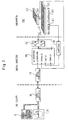
- 10 denotes a machine computer for control the CNC machine.
- the machine computer 10 communicates with a data carrier 20, for example the default data for controlling a milling head (not shown) contains. Via an interface 30 and an interface 40 the specification data is fed to a drive computer 100.
- the Drive computer controls an output stage 60 schematically linear motor 200 shown.
- the linear motor 200 comprises a primary part in a known manner (Reaction part) 210 and a secondary part (stand) 220.
- the speed detection can for example directly from the temporal Course of the magnetic field derived at the location of the sensor become.
- the sensors 250 and 240 send their signals to the drive computer 100, which is a speed control, position control or current control.
- the linear scale is separate from the linear motor in FIG. 1 shown, but it can also be located at the Power transmission interface, d. H. in the air gap between the engine parts. Also for the linear scale or the position sensor can determine the properties of the power transmission medium, d. H. of the electromagnetic field become.
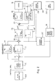
- Fig. 2 shows an example of the structure in greater detail the motor control running in the work computer 100.
- a linear position interpolator 110 From the machine computer 10 or the data carrier 20 the default data on a linear position interpolator 110 given. This data is fed to a subtraction element 111, the inverting input of the actual position data from the linear scale 230 via a high-resolution position interface 50 are supplied. Then the Difference fed to a position controller 112, its output data are fed to a further subtraction element 120. For the formation of the speed difference at known technology, the output signal of the position interface 50 differentiated in a differentiator 250 'and supplied to the subtraction member 120. The subtractor a circuit for determining the acceleration deviation closes on, namely in a circuit 270 determines the target acceleration from which the actual acceleration is subtracted by another differentiator 260 'was derived. A subsequent rule section from a current regulator 130, an output stage 60 and a Current vector generator 132 forms the drive current for the synchronous linear motor 200.
- the regulation shown thus represents a cascaded regulation represents, in addition a speed feedforward control 122 can be made in addition a speed pilot signal to the subtractor 120 is given.
- the inventive control scheme deviates from from the control scheme shown above in that instead of of the differentiating element 250 'is an additional sensor 250 is provided directly on or in the synchronous linear motor. This Sensor 250 immediately determines the speed of the primary part of the engine and directs a corresponding one Signal to subtractor 120.
- a separate acceleration sensor can also be used for acceleration measurement 260 should be provided, without differentiation the acceleration signal to the subtractor 272 outputs, so that the differentiator 260 'is dispensed with can be.
- the differentiators 250 ', 260' by appropriate sensors 250, 260, which directly record the state of motion of the motor, replaced.
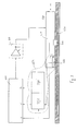
- the speed sensor 250 a coil sensor located near the Air gap of the linear motor 200 is arranged and that electromagnetic field detected in the air gap. That means, that the sensor detects the electromagnetic field directly, on which the power transmission of the engine is based.
- the coils of the sensor 250 are subjected to electrical voltages induced that is proportional to the temporal change in the magnetic field and therefore proportional (with a stationary magnetic field) to speed.
- the (analog) signal of the Coil sensor 250 will be described later Signal processing in a converter 252, if necessary after quantization, as a speed signal v to the drive computer 100 fed.
- the signal from the coil sensor 250 is furthermore an acceleration proportional to the differentiator 260 'already explained Signal a derived and also fed to the drive computer 100.
- About the amplifier or the output stage 60 is controlled by the drive computer 100 Movement of the secondary part 210 of the linear motor 200.
- the exemplary embodiment according to FIG. 3 has the decisive one Advantage that directly a speed proportional Signal from sensor 250 is emitted. This eliminates the Need from an already discrete position signal derive another quantized speed signal.
- this embodiment also with regard to the acceleration control decisive advantages.
- acceleration only by simply differentiating the speed signal preserved and not as with the stand the technology, by twofold differentiation of a position signal.
- the second is the speed sensor 250 arranged directly at the force interface, and that acceleration signal derived from the speed signal a therefore corresponds directly to the differential acceleration between the primary part 210 and the secondary part 220.
- a double acceleration measurement, on the one hand on the primary part 220, on the other hand on the secondary part 210, with subsequent Difference formation to determine the actual Differential acceleration is not required.
- the signal converter 252 already mentioned is provided for processing the signal from the sensor 250, the function of which is explained below.
- the coil sensor 250 is arranged directly at the force interface of the motor 200, ie it runs on the same magnetic track as the primary part 210.
- the signal of the speed sensor 250 in the signal converter 252 is advantageously first rectified, and the signal of the travel sensor 240 is additionally fed to the speed converter.
- the speed data of the sensor 250 and the position data of the displacement sensor 240 are simultaneously recorded and correlated with one another, so that the position-dependent position of the speed signal can be determined at a constant speed of the secondary part 210.
- a correction function v * ( s ) is then determined in a known manner from the location-dependent function v ( s ) of the speed signal, which indicates how the signal of the sensor 250 must be corrected in order to determine a speed signal that is constant at all locations .
- the value pairs s i , v * i , for each location point can then be stored, for example, in a look-up table in the signal converter 252, so that the corresponding correction value v * i and the signal of the speed sensor 250 can be called up for each location point s i can be corrected accordingly in an evaluation logic (not shown).
- the signal converter 252, the differentiator 260 'and the sensor 250 can be combined to form a unit, as indicated by the broken line 254 in FIG. 3.
- This unit 254 is then integrated directly into the primary part 210 of the motor 200, so that the motor 200 only has connections for the position signal s , the speed signal v and the acceleration signal a to the outside.
- the correction function can, for example, be updated automatically at regular intervals or always at the start of operation in order to take gradual changes, for example due to wear, into account.
Landscapes
- Engineering & Computer Science (AREA)
- Human Computer Interaction (AREA)
- Manufacturing & Machinery (AREA)
- Physics & Mathematics (AREA)
- General Physics & Mathematics (AREA)
- Automation & Control Theory (AREA)
- Control Of Linear Motors (AREA)
- Control Of Electric Motors In General (AREA)
- Control Of Position Or Direction (AREA)
Description
Die Erfindung bezieht sich auf eine Regeleinrichtung für
einen Motor von der im Oberbegriff des Patentanspruchs 1
angegebenen Art sowie auf ein Verfahren zur Steuerung eines
Motors.The invention relates to a control device for
an engine of the type mentioned in the preamble of
Regeleinrichtungen zum Betrieb von Motoren sind allgemein bekannt, z.B. aus WO-85 05 710 A1. Zu diesem Zweck wird beispielsweise über einen Sensor der Bewegungszustand bzw. die Lage des Motors ermittelt und der Regeleinrichtung zugeführt, die den Motor abhängig von der Differenz zwischen Soll- und Istwert der Motorparameter betreibt. Auf diese Weise können auch zeitlich veränderliche Vorgabewerte wie Lage, Geschwindigkeit oder Beschleunigung relativ genau eingehalten werden.Control devices for operating motors are general known, e.g. from WO-85 05 710 A1. For this purpose, for example Sensor determines the state of motion or the position of the motor and fed to the control device, which depends on the engine the difference between the setpoint and actual value of the motor parameters operates. This way you can also timed variable default values such as position, speed or Acceleration are observed relatively accurately.
Im Zuge der technischen Weiterentwicklung werden jedoch die Anforderungen an die Präzision der Reglung von beispielsweise Elektromotoren, aber auch Fluid- oder Verbrennungsmotoren, immer höhere Anforderungen gestellt.In the course of technical development, however Requirements for the precision of the regulation, for example Electric motors, but also fluid or internal combustion engines, increasingly demanding requirements.
Insbesondere bei modernen Fertigungsautomaten wie Geräten zum Bonden, Bestückungsautomaten, Fräsmaschinen und dergleichen müssen einander widersprechende Anforderungen von einer Regeleinrichtung erfüllt werden.Especially with modern production machines such as devices for bonding, automatic placement machines, milling machines and the like have conflicting requirements from a control device.
So muß ein Bestückungsautomat zur Bestückung von Schaltungsplatinen mit elektronischen Bauelementen eine Punkt-zu-Punkt-Bewegung ausführen, bei der einerseits der Punkt zum Einsetzen des Bauelementes sehr genau angesteuert werden muß, andererseits die Punkt-zu-Punkt-Bewegung mit hoher Geschwindigkeit erfolgen soll, was, bedingt durch die Beschleunigungen und Abbremsungen, zu Schwingungen im System führt, die wiederum die Genauigkeit bei der Positionierung beeinträchtigen. Dies gilt auch für moderne Fräsmaschinen, bei denen ein relativ kleiner Fräskopf für verschieden große Fräsöffnungen und -konturen verwendet wird. Auch hier muß eine große Lagegenauigkeit mit einer hohen Geschwindigkeit bzw. Beschleunigung des Fräskopfes verbunden werden.So an automatic assembly machine must be used to assemble circuit boards a point-to-point movement with electronic components execute, on the one hand the point can be controlled very precisely for inserting the component must, on the other hand, the point-to-point movement with high Speed should take place due to the accelerations and decelerations, to vibrations in the system which in turn leads to accuracy in positioning affect. This also applies to modern milling machines, where a relatively small milling head for different large milling openings and contours is used. Here too must have great positional accuracy at high speed or acceleration of the milling head.
Bei herkömmlichen Werkzeugmaschinen wie Fräsmaschinen oder dergleichen oder auch bei Bestückungsautomaten werden als translatorische Antriebe Kugelrollspindelantriebe verwendet, bei denen ein Elektromotor eine Kugelrollspindel antreibt, die ihrerseits einen Werkzeugtisch oder einen Werkstücktisch verschiebt. Die Motorregelung erfolgt dann einerseits über einen Drehgeber am Motor sowie über einen Linearmaßstab am Werkzeugtisch.With conventional machine tools such as milling machines or the same or in the case of automatic placement machines are considered translatory drives ball screw drives used, where an electric motor drives a ball screw, which in turn is a tool table or a workpiece table shifts. The motor control then takes place on the one hand via a rotary encoder on the motor and a linear scale at the tool table.
Dabei hat sich jedoch gezeigt, daß alle mechanischen Bauelemente des Kugelrollspindelantriebs einen nachteiligen Einfluß auf die Regelstrecke ausüben, d. h. Zeitverzögerungen aufgrund der Elastizitätseigenschaften der Spindel, der Schwingungen des Werkstücks oder des Werkzeugtisches etc. wirken sich als Phasendrehungen in der Regelstrecke aus, was zu einem Schwingungsproblem führt.However, it has been shown that all mechanical components of the ball screw drive a disadvantage Exert influence on the controlled system, d. H. Time delays due to the elastic properties of the spindle, the Vibrations of the workpiece or the tool table etc. act as phase rotations in the controlled system, which leads to a vibration problem.
In einem gewissen Ausmaß kann dieses Problem durch Einsatz von Direktantrieben, d. h. elektromagnetischen Linearmotoren, vermindert werden, da z. B. das mechanische Element der Kugelrollspindel bei einem linearen Direktantrieb entfällt. Allerdings ist auch hier zu beachten, daß alle mechanischen Elemente wie die Aufhängung des Fräskopfes, des Werkstücktisches etc. einen nachteiligen Einfluß auf die Regelstrecke ausüben, wenn auch in reduziertem Maß. Darüberhinaus werden auch Einflüsse der Regelschaltung selbst wichtig. Bei einer Geschwindigkeitsregelung wird im allgemeinen ein Geschwindigkeits-Istsignal aus einem Positions-Istsignal abgeleitet und mit einem Geschwindigkeits-Sollsignal verglichen. Durch die zeitliche Ableitung wird so eine Verzögerung in das System eingebracht, die sich als Phasenverschiebung oder -drehung auf die Regelstrecke nachteilig auswirkt. Ferner ist zu beachten, daß normalerweise die Positionsdaten diskret aufgenommen werden, wodurch sich ein Quantisierungsrauschen ergibt, das bei der zeitlichen Ableitung noch verstärkt wird. Entsprechende Überlegungen gelten in verstärktem Maße für eine mögliche Beschleunigungsregelung.To some extent, this problem can be resolved through use of direct drives, d. H. electromagnetic linear motors, can be reduced because z. B. the mechanical element the ball screw in a linear direct drive is not required. However, it should also be noted here that all mechanical Elements such as the suspension of the milling head, the Workpiece table etc. has an adverse impact on the Exercise the controlled system, albeit to a reduced extent. Furthermore are also influences of the control circuit itself important. With a cruise control in general an actual speed signal from an actual position signal derived and with a target speed signal compared. Due to the time derivation such a Delay introduced into the system, which is called a phase shift disadvantageous or rotation on the controlled system affects. It should also be noted that normally the position data be recorded discreetly, which makes a Quantization noise results in the time derivative is reinforced. Appropriate considerations apply to a greater extent to a possible acceleration control.
Entsprechende Probleme ergeben sich auch bei der sogenannten kaskadierten Regelung, bei der mehrere Regler hintereinandergeschaltet sind, beispielsweise eine Lagereglung, eine Geschwindigkeitsregelung und eine Beschleunigungsregelung.Corresponding problems also arise with the so-called cascaded control, in which several controllers are connected in series are, for example a position control, a speed control and an acceleration control.
Zwar läßt sich die Regelgenauigkeit durch Einsatz einer sogenannten Vorsteuerung, bei der beispielsweise dem Geschwindigkeitsregler zusätzlich ein aus den Sollwerten abgeleitetes Geschwindigkeitsvorsteuersignal zugeführt wird, noch weiter steigern, die oben dargestellten Probleme hinsichtlich der Phasendrehung, Phasenverschiebung und der Verzögerung bleiben jedoch erhalten.The control accuracy can be achieved by using a so-called Feedforward control, for example with the speed controller additionally one derived from the target values Speed pilot signal is supplied, to further increase the problems outlined above the phase shift, phase shift and the However, delays remain.
Der Erfindung liegt somit die Aufgabe zugrunde, eine Regeleinrichtung für einen Motor zu schaffen, die eine schnelle und genaue Regelung des Bewegungszustandes des Motors ermöglicht; desweiteren soll ein entsprechendes Verfahren zur Regelung eines Motors geschaffen werden.The invention is therefore based on the object of a control device for an engine to create a quick one and allows precise control of the state of motion of the engine; furthermore, a corresponding method for Regulation of an engine can be created.
Diese Aufgabe wird durch eine Regeleinrichtung gemäß Anspruch
1 bzw. durch ein Verfahren zur Regelung eines Motors
gemäß Anspruch 11 gelöst; die abhängigen Ansprüche betreffen
weitere Entwicklungen der Erfindung. This object is achieved by a control device according to
Erfindungsgemäß ist der Sensor zur Erfassung des Bewegungszustandes des Motors an der Kraftübertragungsstelle des Motors angeordnet. Auf diese Weise können alle Änderungen des Bewegungszustandes des Motors direkt erfaßt und dem Regler zugeführt werden, so daß eine unmittelbare Regelung möglich ist, die im wesentlichen frei von mechanischen Einflüssen und/oder Einflüssen der Regeleinrichtung wie Differenzierung etc. ist.According to the invention, the sensor for detecting the state of motion of the engine at the power transmission point of the engine arranged. This way, all changes to the Movement state of the motor directly recorded and the controller are supplied so that an immediate regulation is possible which is essentially free of mechanical influences and / or influences of the control device such as differentiation etc. is.
Der Sensor erfaßt direkt zumindest einen Zustandsparameter des Kraftübertragungsmediums an der Kraftübertragungsstelle des Motors, beispielsweise den Druckzustand eines Fluids oder die elektrische und/oder magnetische Feldstärke eines Elektromotors, d.h. des Feldes, das auch der Kraftübertragung im Motor dient. Dieser Zustandsparameter ist unmittelbar eine Maßgabe für den Bewegungszustand bzw. für Änderungen des Bewegungszustandes des Motors; zu diesem Zweck ist der Sensor im weitesten Sinne "im" Kraftübertragungsmedium des Motors angeordnet.The sensor directly detects at least one state parameter of the power transmission medium at the power transmission point of the engine, for example the pressure state of a fluid or the electrical and / or magnetic field strength of a Electric motor, i.e. of the field, which is also the power transmission serves in the engine. This state parameter is immediate a measure of the state of movement or changes the state of motion of the engine; is for this purpose the sensor in the broadest sense "in" the power transmission medium arranged of the engine.
Der Sensor kann ein Winkellagengeber, ein Winkelgeschwindigkeitsgeber oder ein Winkelbeschleunigungsgeber im Fall eines Rotationsmotors sein oder ein Weggeber, ein Geschwindigkeitsgeber und/oder ein Beschleunigungsgeber im Fall eines Linearmotors.The sensor can be an angular position encoder, an angular velocity encoder or an angular accelerator in the case a rotary motor or a displacement sensor, a speed sensor and / or an accelerometer in the case of a Linear motor.
Bei dem erfindungsgemäßen Verfahren wird der Bewegungszustand des Motors unmittelbar an der Kraftübertragungsschnittstelle ermittelt, und zwar vorteilhafterweise über das Kraftübertragungsmedium.In the method according to the invention, the state of motion of the engine directly at the power transmission interface determined, and advantageously via the power transmission medium.
Das Regelungsverfahren kann dabei vorteilhafterweise mit einer Kaskadenregelung mit einer Geschwindigkeits- und/oder Beschleunigungsreglung kombiniert werden; auch ist es möglich, eine Geschwindigkeits- und/oder Beschleunigungsvorsteuerung einzusetzen. The control method can advantageously with a cascade control with a speed and / or Acceleration control can be combined; it is also possible a speed and / or acceleration pre-control to use.
Ausführungsbeispiele der Erfindung werden anhand der beigefügten Zeichnungen erläutert. Es zeigen:
- Fig. 1
- eine schematische Darstellung einer CNC-gesteuerten Werkzeugmaschine mit einem Linearmotor,
- Fig. 2
- eine schematisch Darstellung eines erfindungsgemäßen Reglers, und
- Fig. 3
- eine weitere schematische Darstellung einer CNC-Maschine mit Linearmotor.
- Fig. 1
- 1 shows a schematic representation of a CNC-controlled machine tool with a linear motor,
- Fig. 2
- a schematic representation of a controller according to the invention, and
- Fig. 3
- another schematic representation of a CNC machine with a linear motor.
In Fig. 1 bezeichnet 10 einen Maschinenrechner zur Steuerung
der CNC-Maschine. Der Maschinenrechner 10 kommuniziert
mit einem Datenträger 20, der beispielsweise Vorgabedaten
zur Steuerung eines Fräskopfes (nicht dargestellt) enthält.
Über eine Schnittstelle 30 und eine Schnittstelle 40 werden
die Vorgabedaten einem Antriebsrechner 100 zugeführt. Der
Antriebsrechner steuert über eine Endstufe 60 einen schematisch
dargestellten Linearmotor 200.In Fig. 1, 10 denotes a machine computer for control
the CNC machine. The
Der Linearmotor 200 umfaßt in bekannter Weise ein Primärteil
(Reaktionsteil) 210 und ein Sekundärteil (Ständer)
220. Schematisch dargestellt sind ein Linearmaßstab 230 und
ein Weggeber 240. An oder in der Kraftübertragungsschnittstelle
des Linarmotors, nämlich dem Luftspalt zwischen dem
Primär- und dem Sekundärteil, ist ein Sensor 250 zur direkten
Erfassung der Geschwindigkeit vorgesehen. Die Geschwindigkeitserfassung
kann beispielsweise direkt aus dem zeitlichen
Verlauf des Magnetfeldes am Ort des Sensors abgeleitet
werden.The
Die Sensoren 250 und 240 geben ihre Signale an den Antriebsrechner
100, der eine Geschwindigkeitssteuerung, Lagesteuerung
bzw. Stromsteuerung vornimmt. The
Der Linearmaßstab ist in Fig. 1 separat vom Linearmotor dargestellt, er kann sich jedoch ebenfalls am Ort der Kraftübertragungsschnittstelle, d. h. im Luftspalt zwischen den Motorteilen befinden. Auch für den Linearmaßstab bzw. den Wegsensor können die Eigenschaften des Kraftübertragungsmediums, d. h. des elektromagnetischen Feldes, ausgenutzt werden.The linear scale is separate from the linear motor in FIG. 1 shown, but it can also be located at the Power transmission interface, d. H. in the air gap between the engine parts. Also for the linear scale or the position sensor can determine the properties of the power transmission medium, d. H. of the electromagnetic field become.
Fig. 2 zeigt im größeren Detail ein Beispiel für den Aufbau
der im Arbeitsrechner 100 ablaufenden Motorregelung.Fig. 2 shows an example of the structure in greater detail
the motor control running in the
Von dem Maschinenrechner 10 bzw. dem Datenträger 20 werden
die Vorgabedaten an einem linearen Lageinterpolierer 110
gegeben. Diese Daten werden einem Subtraktionsglied 111 zugeführt,
dessen invertierendem Eingang die Lage-Ist-Daten
vom Linearmaßstab 230 über eine hochauflösendes Positionsschnittstelle
50 zugeführt werden. Anschließend wird die
Differenz einem Lageregler 112 zugeführt, dessen Ausgangsdaten
einem weiteren Subtraktionsglied 120 zugeführt werden.
Zur Bildung der Geschwindigkeitsdifferenz wird bei der
bekannten Technik das Ausgangssignal der Positionsschnittstelle
50 in einem Differenzierglied 250' differenziert und
dem Substraktionsglied 120 zugeführt. Dem Subtraktionsglied
schließt sich eine Schaltung zur Ermittlung der Beschleunigungsabweichung
an, und zwar wird in einer Schaltung 270
die Sollbeschleunigung ermittelt, von der die Istbeschleunigung
subtrahiert wird, die durch eine weiteres Differenzierglied
260' abgeleitet wurde. Ein anschließender Regelteil
aus einem Stromregler 130, einer Endstufe 60 und einem
Stromvektorbildner 132 bildet daraus den Antriebsstrom für
den Synchronlinearmotor 200.From the
Die dargestellte Regelung stellt somit eine kaskadierte Regelung
dar, wobei zusätzlich noch eine Geschwindigkeitsvorsteuerung
122 vorgenommen werden kann, bei der zusätzlich
ein Geschwindigkeitsvorsteuersignal auf das Subtrahierglied
120 gegeben wird.The regulation shown thus represents a cascaded regulation
represents, in addition a
Da die Informationen hinsichtlich des Geschwindigkeits-Istwertes und des Beschleunigungs-Istwertes über Differenzierglieder 250' und 260' ermittelt werden, ergeben sich neben den mechanischen Beeinflussungen des Regelsystems auch negative Einflüsse wegen Signalverzögerungen, Phasendrehungen etc.Because the information regarding the actual speed value and the actual acceleration value via differentiators 250 'and 260' are determined in addition to the mechanical influences of the control system also negative Influences due to signal delays, phase shifts Etc.
Aufgrund dessen weicht das erfinderische Regelschema von
dem oben dargestellten Regelschema dadurch ab, daß anstatt
des Differenziergliedes 250' ein zusätzlicher Sensor 250
direkt am oder im Synchronlinearmotor vorgesehen ist. Dieser
Sensor 250 ermittelt unmittelbar die Geschwindigkeit
des Primärteils des Motors und leitet ein entsprechendes
Signal an das Subtrahierglied 120.Because of this, the inventive control scheme deviates from
from the control scheme shown above in that instead of
of the differentiating element 250 'is an
Auch für die Beschleunigungsmessung kann ein separater Beschleunigungssensor
260 vorgesehen sein, der ohne Differenzierung
das Beschleunigungssignal an das Subtrahierglied
272 abgibt, so daß auf das Differenzierglied 260' verzichtet
werden kann. Erfindungsgemäß werden somit die Differenzierglieder
250', 260' durch entsprechende Sensoren 250,
260, die direkt den Bewegungszustand des Motors erfassen,
ersetzt.A separate acceleration sensor can also be used for
Eine vorteilhafter Umsetzung des erfindungsgemäßen Prinzips ist aus der schematischen Darstellung der Figur 3 ersichtlich. Die Figur entspricht im wesentlichen der Figur 1, wobei die verschiedenen Schnittstellen weggelassen wurden.An advantageous implementation of the principle according to the invention can be seen from the schematic representation of Figure 3. The figure corresponds essentially to Figure 1, wherein the different interfaces have been omitted.
Bei dem Ausführungsbeispiel gemäß Figur 3 ist der Geschwindigkeitssensor
250 ein Spulensensor, der in der Nähe des
Luftspaltes des Linearmotors 200 angeordnet ist und das
elektromagnetische Feld im Luftspalt erfaßt. Das bedeutet,
daß der Sensor direkt das elektromagnetische Feld erfaßt,
auf dem die Kraftübertragung des Motors beruht. In der oder
den Spulen des Sensors 250 werden elektrische Spannungen
induziert, die proportional zur zeitlichen Änderung des Magnetfeldes
und damit (bei stationärem Magnetfeld) proportional
zur Geschwindigkeit sind. Das (analoge) Signal des
Spulensensors 250 wird nach einer später zu erläuternden
Signalverarbeitung in einem Umsetzer 252, gegebenenfalls
nach Quantisierung, als Geschwindigkeitssignal v dem Antriebsrechner
100 zugeführt. Aus dem geschwindigkeitsproportionalen
Signal des Spulensensors 250 wird desweiteren
über das bereits erläuterte Differenzierglied 260' ein beschleunigungsproportionales
Signal a abgeleitet und ebenfalls
dem Antriebsrechner 100 zugeführt. Über den Verstärker
bzw. die Endstufe 60 regelt der Antriebsrechner 100 die
Bewegung des Sekundärteils 210 des Linearmotors 200.In the embodiment shown in Figure 3 is the speed sensor
250 a coil sensor located near the
Air gap of the
Das Ausführungsbeispiel gemäß Figur 3 hat den entscheidenden
Vorteil, daß direkt ein geschwindigkeitsproportionales
Signal vom Sensor 250 abgegeben wird. Es entfällt somit die
Notwendigkeit, aus einem bereits diskreten Positionssignal
ein weiteres, quantisiertes Geschwindigkeitssignal abzuleiten.The exemplary embodiment according to FIG. 3 has the decisive one
Advantage that directly a speed proportional
Signal from
Obwohl bei dieser Ausführungsform ein Differenzierglied
260' für die Beschleunigungsmessung eingesetzt wird, hat
diese Ausführungsform auch hinsichtlich der Beschleunigungsregelung
entscheidene Vorteile. Zum einen wird die Beschleunigung
nur durch einfache Differenzierung des Geschwindigkeitssignals
erhalten und nicht, wie beim Stand
der Technik, durch eine zweifache Differenzierung eines Positionssignals.
Zum zweiten ist der Geschwindigkeitssensor
250 direkt an der Kraftschnittstelle angeordnet, und das
aus dem Geschwindigkeitssignal abgeleitete Beschleunigungssignal
a entspricht somit direkt der Differenzbeschleunigung
zwischen dem Primärteil 210 und dem Sekundärteil 220. Although a differentiator in this embodiment
260 'is used for the acceleration measurement
this embodiment also with regard to the acceleration control
decisive advantages. Firstly, acceleration
only by simply differentiating the speed signal
preserved and not as with the stand
the technology, by twofold differentiation of a position signal.
The second is the
Eine zweifache Beschleunigungsmessung, einerseits am Primärteil
220, andererseits am Sekundärteil 210, mit anschließender
Differenzbildung zur Ermittlung der tatsächlichen
Differenzbeschleunigung ist dabei nicht erforderlich.A double acceleration measurement, on the one hand on the
Vorzugsweise ist bei dem Ausführungsbeispiel der Figur 3
zur Verarbeitung des Signals des Sensors 250 der schon erwähnte
Signalumsetzer 252 vorgesehen, dessen Funktion im
Folgenden erläutert wird. Der Spulensensor 250 ist direkt
an der Kraftschnittstelle des Motors 200 angeordnet, d.h.
er läuft auf der gleichen Magnetspur wie das Primärteil
210. Dabei erfaßt der Sensor nur seine lokale Umgebung,
d.h. der Sensor 250 "sieht" nur einen sehr begrenzten Bereich.
Bauartbedingt (abwechselnde N- und S-Magnetpole im
Primärteil) und aufgrund von Fertigungstoleranzen können
dabei Abhängigkeiten des an sich nur geschwindigkeitsproportionalen
Signals des Sensors 250 vom Erfassungsort s
auftreten, d.h. es gilt v = f(s). Wenn man somit in der
Praxis den Motor beispielsweise mit einer konstanten Geschwindigkeit
betreibt, d.h. den Primärteil 210 mit einer
konstanten Geschwindigkeit von einem Ende des Sekundärteils
220 zum anderen Ende bewegt, wird man einer Variation des
Geschwindigkeitssignals v in Abhängigkeit vom Ort s feststellen.
Diese Ortsabhängigkeit des Geschwindigkeitssignals
wird im Signalumsetzer 252 kompensiert.In the exemplary embodiment in FIG. 3, the
Zu diesem Zweck wird vorteilhafterweise das Signal des Geschwindigkeitssensors
250 im Signalumsetzer 252 zunächst
gleichgerichtet, und dem Geschwindigkeitsumsetzer wird zusätzlich
das Signal des Weggebers 240 zugeführt. Bei einem
Testlauf, bei dem der Primärteil 210 ein oder mehrere Male
mit konstanter Geschwindigkeit über die gesamte Länge des
Sekundärteils 220 bewegt wird, werden gleichzeitig die Geschwindigkeitsdaten
des Sensors 250 und die Positionsdaten
des Weggebers 240 aufgenommen und miteinander korreliert,
so daß die Ortsabhängigkeit des Geschwindigkeitssignals bei
einer konstanten Geschwindigkeit des Sekundärteils 210 ermittelt
werden kann. Aus der Ortsabhängigkeitsfunktion v(s)
des Geschwindigkeitssignals wird anschließend in bekannter
Weise eine Korrekturfunktion v*(s) ermittelt, die angibt,
in welcher Weise das Signal des Sensors 250 korrigiert werden
muß, um bei konstanter Geschwindigkeit ein an allen Orten
konstantes Geschwindigkeitssignal zu ermitteln. Die
Wertepaare si, v*i , zu jedem Ortspunkt können dann beispielsweise
in einer Nachschlagtabelle im Signalumsetzer
252 abgelegt werden, so daß bei der späteren Regelung zu
jedem Ortspunkt si der entsprechende Korrekturwert v*i abgerufen
werden kann und das Signal des Geschwindigkeitssensors
250 in einer nicht dargestellten Auswertelogik entsprechend
korrigiert werden kann. Die Einzelheiten, wie
eine derartige Auswertelogik aufzubauen ist und wie eine
Nachschlagtabelle im Signalumsetzer 252 mittels eines Speichers
zu realisieren ist, sind dem Fachmann geläufig und
werden deshalb nicht näher dargestellt. Dabei ist es auch
grundsätzlich möglich, die Korrekturfunktion v*(s) nicht
als Nachschlagtabelle abzulegen sondern über einen Funktionsgenerator
zu generieren, der die Funktion v*(s) möglichst
genau wiedergibt, beispielsweise durch angepaßte
trigonometrische Funktionen od.dgl.For this purpose, the signal of the
Schließlich sei noch erwähnt, daß der Signalumsetzer 252,
das Differenzierglied 260' und der Sensor 250 zu einer Einheit
zusammengefaßt werden können, wie durch die gestrichelte
Linie 254 in Figur 3 angedeutet ist. Diese Einheit
254 wird dann direkt im Primärteil 210 des Motors 200 integriert,
so daß der Motor 200 nur noch Anschlüsse für das
Positionssignal s, das Geschwindigkeitssignal v und das Beschleunigungssignal
a nach außen aufweist. Desweiteren ist
es auch möglich, die Korrekturfunktion nicht nur in einem
anfänglichen Testlauf zu ermitteln sondern in zeitlichen
Abständen, abhängig von dem Einsatz des Motors. So kann die
Korrekturfunktion beispielsweise in regelmäßigen Intervallen
oder immer zum Betriebsbeginn automatisch aktualisiert
werden, um so allmähliche Veränderungen, z.B. aufgrund von
Verschleiß, berücksichtigen zu können.Finally, it should also be mentioned that the
Claims (22)
- Regulating device for a motor (200), the motor (200) having at least two motor components (210, 220) which interact with one another via a force-transmission interface (270) and can be moved relative to one another, a sensor (250) for sensing the movement status of the motor components and a regulator (100) for regulating the movement status of the motor as a function of signals from the sensor, characterized in that the sensor is assigned to the force-transmission interface (270) of the motor (200) and registers at least one status parameter of the force-transmission medium of the motor.
- Regulating device according to Claim 1, characterized in that the sensor is arranged in the force-transmission medium of the motor.
- Regulating device according to Claim 1 or 2, characterized in that the force-transmission medium of the motor is a fluid or an electromagnetic field.
- Regulating device according to one of Claims 1 to 3, characterized in that the motor is a rotation motor and the sensor is an angular position sensor, an angular velocity sensor and/or an angular acceleration sensor.
- Regulating device according to one of Claims to 4, characterized in that the motor is a linear motor, and the sensor is a displacement sensor, a velocity sensor and/or an acceleration sensor.
- Regulating device according to one of Claims 4 or 5, characterized in that the sensor registers the electromagnetic field or changes in the electromagnetic field on which the force transmission of the motor depends.
- Regulating device according to Claim 6, characterized in that the sensor (240) is an induction sensor.
- Regulating device according to Claim 7, characterized in that the sensor (250) has one or more coils.
- Regulating device according to one of the preceding claims, characterized by a signal converter (252) which is connected to a displacement sensor (240) and to the sensor (250) for registering the movement status, and has memory means and correction means in order to compensate a possible dependence of the signals from the sensor (250) on the position.
- Method for regulating a motor, the motor having at least two motor components which interact with one another via a force-transmission interface and can be moved relative to one another, characterized in that the movement status of the motor is registered at the force-transmission interface of the motor by means of status parameters of the force-transmission medium of the motor.
- Method according to Claim 10, characterized in that the pressure of a fluid or changes in pressure or the strength of an electromagnetic field or changes in the field are registered at the force-transmission interface of the motor.
- Method according to one of Claims 10 or 11, characterized in that the angular position of the motor components, the angular velocity and/or the angular acceleration are registered at the force-transmission interface.
- Method according to one of Claims 10 to 12, characterized in that a linear path, a linear velocity and/or a linear acceleration are registered at the force-transmission interface of the motor.
- Method according to one of Claims 10 to 13, characterized in that a position-regulating system and a velocity-regulating system are cascaded.
- Method according to Claim 14, characterized in that pilot control of the velocity is performed.
- Method according to Claim 14 or 15, characterized in that a cascaded regulating operation is performed with an acceleration-regulating system.
- Method according to Claim 16, characterized in that pilot control of the acceleration is performed.
- Method according to one of Claims 10 to 17, characterized in that the movement status of the motor is registered with an induction sensor, preferably a sensor (250) with one or more coils, at the force-transmission interface of an electric motor in the form of a signal which is proportional to the velocity.
- Method according to Claim 18, characterized in that the signal which is proportional to the velocity is fed to a velocity-regulating system, and in that the signal which is proportional to the velocity is fed to an acceleration-regulating system after differentiation over time.
- Method according to one of Claims 18 or 19, characterized in that, before the motor is put into operation, the motor is operated one or more times at a constant velocity in a test run, and tne signal which is proportional to the velocity is recorded as a function of the instantaneous position of the motor,in that a correction function (v'(s)) is determined from the instantaneous signal (v) which is proportional to the velocity and from the signals relating to the instantaneous location (s), andin that the signal from the sensor (260) is compensated by means of the correction function in such a way that dependency relationships between the signals from the sensor (250) and the position (s) of the motor are compensated.
- Method according to Claim 20, characterized in that the correction function (v*(s)) is stored in the form of a reference table or generated in the form of an approximation function.
- Use of a regulating device according to one of Claims 1 to 9 or of a regulating method according to one of Claims 10 to 21 in a translatory drive of a machine tool, of a pick-and-place machine, of an automatic bonding machine or the like.
Applications Claiming Priority (3)
| Application Number | Priority Date | Filing Date | Title |
|---|---|---|---|
| DE19622699 | 1996-06-05 | ||
| DE19622699A DE19622699A1 (en) | 1996-06-05 | 1996-06-05 | Control device and method for engines |
| PCT/EP1997/002910 WO1997046924A1 (en) | 1996-06-05 | 1997-06-05 | Motor-regulating device and method |
Publications (3)
| Publication Number | Publication Date |
|---|---|
| EP0902918A1 EP0902918A1 (en) | 1999-03-24 |
| EP0902918B1 true EP0902918B1 (en) | 2000-09-06 |
| EP0902918B2 EP0902918B2 (en) | 2005-01-12 |
Family
ID=7796291
Family Applications (1)
| Application Number | Title | Priority Date | Filing Date |
|---|---|---|---|
| EP97927135A Expired - Lifetime EP0902918B2 (en) | 1996-06-05 | 1997-06-05 | Motor-regulating device and method |
Country Status (6)
| Country | Link |
|---|---|
| US (1) | US6118245A (en) |
| EP (1) | EP0902918B2 (en) |
| JP (1) | JP2000512478A (en) |
| KR (1) | KR20000016377A (en) |
| DE (2) | DE19622699A1 (en) |
| WO (1) | WO1997046924A1 (en) |
Cited By (3)
| Publication number | Priority date | Publication date | Assignee | Title |
|---|---|---|---|---|
| DE10342562A1 (en) * | 2003-09-15 | 2005-04-21 | Siemens Ag | Control device or regulation of an electrical machine |
| DE10243217B4 (en) * | 2001-09-17 | 2009-06-10 | Ford Motor Co., Dearborn | Method and device for demagnetization compensation for an electric motor |
| CN107742997A (en) * | 2017-10-20 | 2018-02-27 | 北京航天发射技术研究所 | Twin shaft indexing mechanism control system, control method and strapdown inertial measurement unit self-calibrating method |
Families Citing this family (17)
| Publication number | Priority date | Publication date | Assignee | Title |
|---|---|---|---|---|
| JP2000191140A (en) * | 1998-12-26 | 2000-07-11 | Minebea Co Ltd | Carrier system using linear motor |
| DE19930777A1 (en) * | 1999-07-03 | 2001-01-04 | Heidenhain Gmbh Dr Johannes | Regulating arrangement for rapid position regulation of electric motor has position, revolution rate, current control loops; position and revolution rate control loops are in parallel |
| DE19952805C5 (en) * | 1999-11-02 | 2011-03-31 | Thielenhaus Technologies Gmbh | Method and device for finish machining of workpieces |
| US20020099473A1 (en) * | 2000-11-08 | 2002-07-25 | Paul Amadeo | Integrated computer-aided design (CAD) and robotic systems for rapid prototyping and manufacture of smart cards |
| JP3592628B2 (en) * | 2000-12-06 | 2004-11-24 | 恒彦 山崎 | Numerical control method |
| DE20114750U1 (en) | 2001-09-06 | 2002-11-28 | Brückner Maschinenbau GmbH, 83313 Siegsdorf | Arrangement for operating a contact roller |
| DE10304970B4 (en) * | 2003-02-06 | 2006-08-10 | Ina - Drives & Mechatronics Gmbh & Co. Ohg | Positioning unit with a force sensor |
| DE10334736A1 (en) * | 2003-07-29 | 2005-02-17 | Rexroth Indramat Gmbh | Linear motor with advancement or motion regulation for use in industrial automated processes, with bearing unit for guiding a secondary component along the desired path |
| US7405525B2 (en) * | 2003-09-15 | 2008-07-29 | Siemens Aktiengesellschaft | Method for the control of an electric machine and/or device for the control thereof |
| DE102006015065A1 (en) * | 2006-03-31 | 2007-10-18 | Siemens Ag | Built-in motor, in particular built-in torque motor |
| US8084969B2 (en) * | 2007-10-01 | 2011-12-27 | Allegro Microsystems, Inc. | Hall-effect based linear motor controller |
| US7936144B2 (en) | 2008-03-06 | 2011-05-03 | Allegro Microsystems, Inc. | Self-calibration algorithms in a small motor driver IC with an integrated position sensor |
| EP2161826B1 (en) * | 2008-09-09 | 2011-03-16 | Siemens Aktiengesellschaft | Transfer device with dynamically changeable driving ranges |
| EP2574821B1 (en) | 2011-09-30 | 2013-10-30 | Siemens Aktiengesellschaft | Active oscillation attenuator without direct acceleration detection |
| EP2574820B1 (en) | 2011-09-30 | 2014-04-16 | Siemens Aktiengesellschaft | Processing machine with oscillation compensation of mobile mechanical structures |
| DE102012210097A1 (en) * | 2012-06-15 | 2013-12-19 | Hilti Aktiengesellschaft | control method |
| CN104793568A (en) * | 2015-04-10 | 2015-07-22 | 深圳市明速自动化设备有限公司 | Multi-axle interpolation method |
Family Cites Families (23)
| Publication number | Priority date | Publication date | Assignee | Title |
|---|---|---|---|---|
| US2020780A (en) † | 1934-05-11 | 1935-11-12 | Jennie B Hamilton | Price tag support |
| US3555254A (en) * | 1967-04-17 | 1971-01-12 | Gerber Scientific Instr Co | Error correcting system and method for use with plotters, machine tools and the like |
| DE2020780A1 (en) † | 1969-04-04 | 1970-12-17 | Pioneer Electronic Corp | Electric DC motor |
| DE2146499C3 (en) * | 1971-09-17 | 1975-09-25 | Messerschmitt-Boelkow-Blohm Gmbh, 8000 Muenchen | Control arrangement for spacing electromagnetic levitation guidance of a levitation vehicle in relation to support and guide rails |
| US3867656A (en) † | 1971-12-13 | 1975-02-18 | Siwa Seikosha Kk | Brushless direct current motor |
| DE2314257C2 (en) † | 1973-03-22 | 1982-10-21 | Papst-Motoren GmbH & Co KG, 7742 St Georgen | Circuit arrangement for speed control of a brushless DC motor |
| JPS534883B2 (en) * | 1973-03-31 | 1978-02-22 | ||
| DE2414721C3 (en) * | 1974-03-27 | 1980-06-19 | Brown, Boveri & Cie Ag, 6800 Mannheim | Method for controlling the rotational speed or speed of a frequency converter-fed three-phase asynchronous machine |
| GB1596681A (en) * | 1977-01-19 | 1981-08-26 | Sony Corp | Drive circuits with speed control for brushless dc motors |
| JPS54139016A (en) * | 1978-04-20 | 1979-10-29 | Pioneer Electronic Corp | Linear motor drive controller |
| DE3148007A1 (en) * | 1981-12-04 | 1983-06-09 | Herbert Prof. Dr.-Ing. 3300 Braunschweig Weh | Pole position detection by means of a combination of two sensor arrangements |
| DE3231966A1 (en) † | 1982-08-27 | 1984-03-01 | Erich 8500 Nürnberg Rabe | ELECTRIC MACHINE |
| US4628499A (en) * | 1984-06-01 | 1986-12-09 | Scientific-Atlanta, Inc. | Linear servoactuator with integrated transformer position sensor |
| DE3526166C2 (en) † | 1984-07-23 | 1996-05-02 | Asahi Chemical Ind | Brushless electric motor and method of manufacturing a coil unit therefor |
| JPH02297611A (en) * | 1989-05-12 | 1990-12-10 | Fanuc Ltd | Sliding mode control system including feedforward of speed and acceleration |
| US5063335A (en) * | 1990-09-11 | 1991-11-05 | Allen-Bradley Company, Inc. | Two-input control with independent proportional and integral gains for velocity error and velocity feedforward including velocity command limiting |
| DE4122769A1 (en) * | 1991-07-10 | 1993-01-21 | Ief Werner Gmbh | POSITION SENSOR FOR LINEAR MOTORS |
| JPH0683403A (en) * | 1992-07-17 | 1994-03-25 | Fanuc Ltd | Adaptive pi control system |
| US5250880A (en) * | 1992-10-22 | 1993-10-05 | Ford Motor Company | Linear motor control system and method |
| DE19543562A1 (en) * | 1994-11-22 | 1996-05-23 | Bosch Gmbh Robert | System for non-contact determination of angle of rotation of rotatable element for e.g. ignition control in motor vehicle |
| US5606236A (en) * | 1995-01-17 | 1997-02-25 | Eaton Corporation | Two wire position sense and control of modulating gas valve or other electromechanical actuators |
| GB2305518B (en) * | 1995-09-26 | 1999-11-03 | Custom Dev Ltd | Electronic actuator position control |
| DE19605413A1 (en) * | 1996-02-14 | 1996-07-11 | Schinkoethe Wolfgang Prof Dr I | DC linear motor for use in position control |
-
1996
- 1996-06-05 DE DE19622699A patent/DE19622699A1/en not_active Withdrawn
-
1997
- 1997-06-05 WO PCT/EP1997/002910 patent/WO1997046924A1/en not_active Ceased
- 1997-06-05 KR KR1019980709951A patent/KR20000016377A/en not_active Withdrawn
- 1997-06-05 DE DE59702321T patent/DE59702321D1/en not_active Expired - Lifetime
- 1997-06-05 US US09/194,757 patent/US6118245A/en not_active Expired - Lifetime
- 1997-06-05 EP EP97927135A patent/EP0902918B2/en not_active Expired - Lifetime
- 1997-06-05 JP JP10500232A patent/JP2000512478A/en active Pending
Cited By (4)
| Publication number | Priority date | Publication date | Assignee | Title |
|---|---|---|---|---|
| DE10243217B4 (en) * | 2001-09-17 | 2009-06-10 | Ford Motor Co., Dearborn | Method and device for demagnetization compensation for an electric motor |
| DE10342562A1 (en) * | 2003-09-15 | 2005-04-21 | Siemens Ag | Control device or regulation of an electrical machine |
| US7378809B2 (en) | 2003-09-15 | 2008-05-27 | Siemens Aktiengesellschaft | Controller for controlling an electric machine |
| CN107742997A (en) * | 2017-10-20 | 2018-02-27 | 北京航天发射技术研究所 | Twin shaft indexing mechanism control system, control method and strapdown inertial measurement unit self-calibrating method |
Also Published As
| Publication number | Publication date |
|---|---|
| JP2000512478A (en) | 2000-09-19 |
| WO1997046924A1 (en) | 1997-12-11 |
| KR20000016377A (en) | 2000-03-25 |
| DE19622699A1 (en) | 1997-12-11 |
| DE59702321D1 (en) | 2000-10-12 |
| EP0902918B2 (en) | 2005-01-12 |
| EP0902918A1 (en) | 1999-03-24 |
| US6118245A (en) | 2000-09-12 |
Similar Documents
| Publication | Publication Date | Title |
|---|---|---|
| EP0902918B2 (en) | Motor-regulating device and method | |
| EP1826533B1 (en) | Magnetic sensor | |
| EP2048556B1 (en) | Method for determining the characteristics of a non-horizontal driven shaft, in particular in a machine tool, as well as suitable applications, corresponding devices and their application | |
| DE3312526A1 (en) | POSITIONING DEVICE WITH HYDRAULIC ACTUATOR | |
| EP2023092B1 (en) | Position measuring device and method for transmitting movement information | |
| DE102014109469A1 (en) | Motor control device | |
| EP2686952B1 (en) | Method and apparatus for adapting commutation for an electronically commutated electrical machine | |
| EP0544108A1 (en) | Semi-active suspension control system for cars | |
| EP0979411B1 (en) | System for detecting rotating speed | |
| EP0203370A1 (en) | Screwing device with motor-driven screw driver | |
| EP0585655B1 (en) | Method and device for position control of a movable member | |
| EP1939704B1 (en) | Method and device for estimating the load torque of electrical drives regulated by revolution speed or position | |
| DE19708894A1 (en) | Position and-or velocity regulation method for NC machine tool axes | |
| DE102006006162A1 (en) | controller structure | |
| DE102007062738A1 (en) | Total drive consisting of several mechanically coupled drives and control for this multiple drive | |
| EP3235677B1 (en) | Method for controlling an electric drive without a position encoder | |
| EP0381784B1 (en) | Electro-hydraulic drive system | |
| DE102017221562A1 (en) | Control device for a servomotor, method for controlling a servomotor and computer program | |
| EP0894292B1 (en) | Electronic control for a control system for a gearbox | |
| DE10304970B4 (en) | Positioning unit with a force sensor | |
| DE19634279A1 (en) | Method and device for accelerated execution of a program by a programmable logic controller | |
| DD239057A1 (en) | CONTROLLER ASSEMBLY FOR THE POSITIONING OF WEAKED MEASURED MECHANICAL REGULATIONS OF DIMENSIONAL SYSTEMS | |
| DE2900019C2 (en) | ||
| DE10139932B4 (en) | Method and device for position-dependent event triggering | |
| DE102014016816A1 (en) | Tuning of a resolver frequency |
Legal Events
| Date | Code | Title | Description |
|---|---|---|---|
| PUAI | Public reference made under article 153(3) epc to a published international application that has entered the european phase |
Free format text: ORIGINAL CODE: 0009012 |
|
| 17P | Request for examination filed |
Effective date: 19990105 |
|
| AK | Designated contracting states |
Kind code of ref document: A1 Designated state(s): DE GB IT |
|
| GRAG | Despatch of communication of intention to grant |
Free format text: ORIGINAL CODE: EPIDOS AGRA |
|
| 17Q | First examination report despatched |
Effective date: 19990805 |
|
| GRAG | Despatch of communication of intention to grant |
Free format text: ORIGINAL CODE: EPIDOS AGRA |
|
| GRAH | Despatch of communication of intention to grant a patent |
Free format text: ORIGINAL CODE: EPIDOS IGRA |
|
| RAP1 | Party data changed (applicant data changed or rights of an application transferred) |
Owner name: SIEMENS LINEAR MOTOR SYSTEMS GMBH & CO. KG |
|
| GRAH | Despatch of communication of intention to grant a patent |
Free format text: ORIGINAL CODE: EPIDOS IGRA |
|
| GRAA | (expected) grant |
Free format text: ORIGINAL CODE: 0009210 |
|
| AK | Designated contracting states |
Kind code of ref document: B1 Designated state(s): DE GB IT |
|
| REF | Corresponds to: |
Ref document number: 59702321 Country of ref document: DE Date of ref document: 20001012 |
|
| ITF | It: translation for a ep patent filed | ||
| GBT | Gb: translation of ep patent filed (gb section 77(6)(a)/1977) |
Effective date: 20001109 |
|
| EN | Fr: translation not filed | ||
| PLBQ | Unpublished change to opponent data |
Free format text: ORIGINAL CODE: EPIDOS OPPO |
|
| PLBI | Opposition filed |
Free format text: ORIGINAL CODE: 0009260 |
|
| PLBF | Reply of patent proprietor to notice(s) of opposition |
Free format text: ORIGINAL CODE: EPIDOS OBSO |
|
| 26 | Opposition filed |
Opponent name: EBM WERKE GMBH & CO. Effective date: 20010602 |
|
| PLBF | Reply of patent proprietor to notice(s) of opposition |
Free format text: ORIGINAL CODE: EPIDOS OBSO |
|
| REG | Reference to a national code |
Ref country code: GB Ref legal event code: IF02 |
|
| PLBF | Reply of patent proprietor to notice(s) of opposition |
Free format text: ORIGINAL CODE: EPIDOS OBSO |
|
| REG | Reference to a national code |
Ref country code: GB Ref legal event code: 732E |
|
| PLAY | Examination report in opposition despatched + time limit |
Free format text: ORIGINAL CODE: EPIDOSNORE2 |
|
| PLBC | Reply to examination report in opposition received |
Free format text: ORIGINAL CODE: EPIDOSNORE3 |
|
| PUAH | Patent maintained in amended form |
Free format text: ORIGINAL CODE: 0009272 |
|
| STAA | Information on the status of an ep patent application or granted ep patent |
Free format text: STATUS: PATENT MAINTAINED AS AMENDED |
|
| 27A | Patent maintained in amended form |
Effective date: 20050112 |
|
| AK | Designated contracting states |
Kind code of ref document: B2 Designated state(s): DE GB IT |
|
| GBTA | Gb: translation of amended ep patent filed (gb section 77(6)(b)/1977) | ||
| PG25 | Lapsed in a contracting state [announced via postgrant information from national office to epo] |
Ref country code: IT Free format text: LAPSE BECAUSE OF NON-PAYMENT OF DUE FEES Effective date: 20050605 |
|
| REG | Reference to a national code |
Ref country code: DE Ref legal event code: R084 Ref document number: 59702321 Country of ref document: DE |
|
| PGFP | Annual fee paid to national office [announced via postgrant information from national office to epo] |
Ref country code: GB Payment date: 20110613 Year of fee payment: 15 |
|
| PGFP | Annual fee paid to national office [announced via postgrant information from national office to epo] |
Ref country code: DE Payment date: 20120820 Year of fee payment: 16 |
|
| GBPC | Gb: european patent ceased through non-payment of renewal fee |
Effective date: 20120605 |
|
| PG25 | Lapsed in a contracting state [announced via postgrant information from national office to epo] |
Ref country code: GB Free format text: LAPSE BECAUSE OF NON-PAYMENT OF DUE FEES Effective date: 20120605 |
|
| REG | Reference to a national code |
Ref country code: DE Ref legal event code: R119 Ref document number: 59702321 Country of ref document: DE Effective date: 20140101 |
|
| PG25 | Lapsed in a contracting state [announced via postgrant information from national office to epo] |
Ref country code: DE Free format text: LAPSE BECAUSE OF NON-PAYMENT OF DUE FEES Effective date: 20140101 |