EP0902544B1 - Modulator und Demodulator - Google Patents
Modulator und Demodulator Download PDFInfo
- Publication number
- EP0902544B1 EP0902544B1 EP98307318A EP98307318A EP0902544B1 EP 0902544 B1 EP0902544 B1 EP 0902544B1 EP 98307318 A EP98307318 A EP 98307318A EP 98307318 A EP98307318 A EP 98307318A EP 0902544 B1 EP0902544 B1 EP 0902544B1
- Authority
- EP
- European Patent Office
- Prior art keywords
- code
- data
- bits
- bit
- restriction
- Prior art date
- Legal status (The legal status is an assumption and is not a legal conclusion. Google has not performed a legal analysis and makes no representation as to the accuracy of the status listed.)
- Expired - Lifetime
Links
Images


Classifications
-
- G—PHYSICS
- G11—INFORMATION STORAGE
- G11B—INFORMATION STORAGE BASED ON RELATIVE MOVEMENT BETWEEN RECORD CARRIER AND TRANSDUCER
- G11B20/00—Signal processing not specific to the method of recording or reproducing; Circuits therefor
- G11B20/10—Digital recording or reproducing
- G11B20/14—Digital recording or reproducing using self-clocking codes
- G11B20/1403—Digital recording or reproducing using self-clocking codes characterised by the use of two levels
- G11B20/1423—Code representation depending on subsequent bits, e.g. delay modulation, double density code, Miller code
- G11B20/1426—Code representation depending on subsequent bits, e.g. delay modulation, double density code, Miller code conversion to or from block codes or representations thereof
-
- H—ELECTRICITY
- H03—ELECTRONIC CIRCUITRY
- H03M—CODING; DECODING; CODE CONVERSION IN GENERAL
- H03M5/00—Conversion of the form of the representation of individual digits
- H03M5/02—Conversion to or from representation by pulses
- H03M5/04—Conversion to or from representation by pulses the pulses having two levels
- H03M5/14—Code representation, e.g. transition, for a given bit cell depending on the information in one or more adjacent bit cells, e.g. delay modulation code, double density code
- H03M5/145—Conversion to or from block codes or representations thereof
-
- G—PHYSICS
- G11—INFORMATION STORAGE
- G11B—INFORMATION STORAGE BASED ON RELATIVE MOVEMENT BETWEEN RECORD CARRIER AND TRANSDUCER
- G11B20/00—Signal processing not specific to the method of recording or reproducing; Circuits therefor
- G11B20/10—Digital recording or reproducing
- G11B20/10009—Improvement or modification of read or write signals
Definitions
- This invention relates to a modulating device and method, and demodulating device and method, and in particular to a modulating device and method, and demodulating device and method, which are suitable for modulating data for data transmission or recording on a recording medium, and demodulating the modulation code obtained by this modulation so as to reproduce the data.
- Block coding converts a data sequence to blocks of m x i bit units (referred to hereafter as data words), and this data word is converted to a code word comprising n x i bits according to a suitable code rule.
- this code is a fixed length code expressed by (d,k;m,n;1).
- a predetermined i is selected from the range 1 to imax (maximum value of i) and the conversion is performed, the code is a variable-length code.
- This block encoded code is represented by a variable length code (d,k;m,n;r).
- i is known as a restriction length
- imax is r (the maximum restriction length).
- the minimum run d shows the minimum number of consecutive "0"s in repeated “1” s in a code sequence.
- the maximum run k shows the maximum number of consecutive "0"s in repeated "1”s in a code sequence.
- NRZI Non Return to Zero Inverted modulation, wherein “1” means inversion and "0” means non-inversion, is performed on the variable length code obtained as above, and the NRZI modulated variable length code (hereafter, referred to as a recorded waveform sequence) is recorded.
- One modulation technique used by magnetic disks or magneto-optical disks, etc. is RLL(1-7).
- the parameters of this modulating technique are (1, 7; 2, 3; 2).
- the symbol x in the conversion table is 1 when the next channel bit is 0, and 0 when the next channel bit is 1.
- the restriction length r is 2.
- the RLL(1-7) code can be formed from fixed length codes. It may be expected that modulation/demodulation will be easier if fixed length codes are used. For example, as the output is always a fixed number of bits, i.e. data words are output two bits at a time, and code words are output three bits at a time, the construction is simple.
- the fixed length conversion table for the RLL(1-7) code is as follows. Herein, to distinguish it from the aforesaid variable-length, the fixed length table will be represented by RLL-F(1-7).
- Table 2 This table is an ISO standard table.
- This RLL-F(1-7) (1,7;2,3;1) may also be obtained by replacing converted data words as in Table 3. Further, demodulation can be performed 1:1 as in the above Table 2.
- Table 3 RLL-F(1,7;2,3;1) (2) Immediately preceding code word Current data word Next data word Converted code word 0 00 11 010 0 00 not 11 100 0 01 0x 010 0 01 1x 101 0 10 0x 000 0 10 1x 001 1 10 11 010 1 10 not 11 000 0 11 0x 000 1 11 0x 010 x 11 1x 001
- the occurrence frequency of 2T which is Tmin is the greatest, 3T, 4T, and 5T are less, and the occurrence frequency of 8T is the least .
- the output waveform amplitude is smaller than for large T such as for example 5T and 6T. This is because the output during playback is smaller the higher the region depending on the optical characteristics of the lens.
- RLL(1-7) is often combined with PRML (Partial Response Maximum Likelihood), to improve S/N during playback of a high density recording.
- This method comprises, for example, Viterbi decoding equalized by PR(1,1) or PR(1,2,1) by matching the RF reproduction waveform to media characteristics.
- waveform equalization is performed to approach this reproduction output.
- the waveform interference becomes longer the higher the linear density, therefore, waveform equalization also becomes longer as in PR(1, 2, 2, 1) or PR(1, 1, 1, 1).
- WO94/18670 A discloses a device for reading data from and writing data to a magnetic storage device.
- This invention which was conceived in view of this situation, aims to permit more stable clock reproduction than in the case of, for example, conventional RLL-F(1-7), which is a fixed length block code, by adding a code which limits the number of times the minimum inversion interval Tmin occurs repeatedly, to a similar modulation table.
- Fig. 1 shows the detailed circuit construction.
- data having a basic data length of two bits is converted to a fixed length code (1, 7; 2, 3; 1) by a conversion table comprising a code which limits a minimum run d in a channel bit sequence of an RLL(1-7) code from occurring a predetermined number of times.
- a shift register 11 divides the input data into two bit lengths, and this is output to a modulation processing unit 13 and delay element 12-1.
- the two bits of data output by the delay element 12-1 is further delayed by a delay element 12-2 and delay element 12-3, and supplied to the modulation processing unit 13.
- the outputs from the delay element 12-1 and delay element 12-2 are both supplied to the modulation processing unit 13.
- a total of eight bits of data i.e. the current two bits and the immediately preceding six bits, is supplied to the modulation processing unit 13.
- the output from the modulation processing unit 13 is resupplied, via a delay element 12-4, to the modulation processing unit 13.
- a clock generation circuit 14 generates a predetermined channel clock and outputs it to a timing control unit 15.
- the timing control unit 15 generates a timing signal which is synchronized with the input channel clock, and outputs it to each unit.
- the fixed length code (d, k; m, n; 1) is, for example, a fixed length code (1,7;2,3;1), i.e. when d which is the minimum run of "0" is 1 bit, k which is the maximum run of "0" is 7 bits, m which is the basic data length is 2 bits, n which is the basic code length is 3 bits, and r which is the maximum restriction length is 1,
- the conversion table is such as is shown for example in the following Table 4.
- the code which limits repetition of the minimum run d is given independently, and if this part is included, the maximum restriction length may be represented by 3.
- the code which limits repetition of the minimum run is added to the fixed length RLL(1-7).
- RML Repeated Minimum Run Length Limited
- the converted code word must maintain the minimum run d. Further, as described hereafter, the maximum run k should also be maintained, although it may not be depending on the case.
- the data output by the shift register 11 is input to the modulation processing unit 13 while being shifted two bits at a time by the delay elements 12-1 to 12-3. Data is also supplied from the input stages of the delay elements 12-1 to 12-3 to the modulation processing unit 13. As a result, the following three blocks of data are input to the modulation processing unit 13 in addition to the current block of data (a total of 8 consecutive bits).
- the modulation processing unit 13 comprises the table shown in Table 4, and converts the input data to code words according to its conversion rule. That is, it converts it to code words referring to the current data word, the following data word, and the immediately preceding code word re-input from the output signal via the delay element 12-4.
- the processing proceeds one block at a time, which is two data word units, and this is output. For example, when the immediately preceding code word bit is "0”, the current data word is "00" and the following data word is "11", the current data word conversion is determined to be “010” and "010” is output. Also, the final "0” is re-input to the modulation processing unit 13 via the delay element 12-4 for subsequent processing.
- the immediately preceding code words input to the modulation processing unit 13 may be the three code words that were output, or the last code word of nine code words may be input. For example, when RML conversion is performed the output is "100-000-001", but it is re-input to the modulation processing unit 13 via the delay element 12-4 and the last "1" is used for subsequent conversion processing.
- Fig. 2 For comparison, the construction of the modulating unit when data is modulated using Table 2, which is a conventional fixed length RLL(1-7) code, is shown in Fig. 2.
- Table 2 which is a conventional fixed length RLL(1-7) code
- Fig. 2 data output by the shift register 11 is supplied two bits at a time to a modulation processing unit 23 and a delay element 22-1. After the delay element 22-1 has delayed the input two bits of data, it is output to the modulation processing unit 23. Of the data output by the modulation processing unit 23, the last bit is re-input to the modulation processing unit 23 via a delay processing unit 22-2.
- the delay element may comprise only one stage.
- the modulation processing unit 23 converts data into code words according to the conversion rules shown in Table 2.
- the code words thus determined are always three bits, and these are timing controlled so that they are output every other three bits.
- the modulating unit which performs modulation based on the fixed length RLL (1-7) code of Table 3 has an identical construction to that shown in Fig. 2.
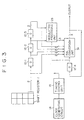
- Fig. 3 is another example of a different modulating unit which performs modulation according to Table 4, which is a fixed length RML (1-7) code.
- the modulation processing unit 13 of Fig. 1 is here split into the modulation processing unit 23 identical to that of Fig. 2, which performs conventional RLL processing, and an RML conversion unit 31, which performs RML conversion.
- the three bit code output by the modulation processing unit 23 is input to the RML processing unit 31.
- RML conversion is not performed, the three bits are output as a code word without modification, and when RML is performed, they are output as a code word after substituting by "100-000-001".
- modulation is performed by the F-RML(1-7) code of Table 4 which has a code limiting the minimum run repeat length to 5.
- the converted code word "010-000-001" may be used as the code limiting the repeat length of the minimum run d, as shown in the following Table 5.
- Table 5 is also obtained by adding an RML code to the fixed length RLL(1-7) code of Table 3.
- the maximum run k need not necessarily be maintained. That is, although the minimum run is closely related to recording and reproduction, and must therefore be maintained, the same is not true of the maximum run, so some formats may even comprise a T which is larger than the maximum run.
- Table 8 is a demodulation table of the F-RML (1-7) code table, Table 4.
- Table 8 DEM-RML-F(1,7;2,3;1 ⁇ 3>) Immediately preceding code word Current code word Next code word Demodulated data word x10 000 xxx 11 not x10 000 xxx 10 x00 001 xxx 10 not x00 001 xxx 11 xx1 010 00x 10 xx1 010 not 00x 11 xx0 010 00x 00 xx0 010 not 00x 01 x 01 x 100 xxx 00 xxx 101 xxx 01 xxx 100 000-001 01-11-01
- Fig. 4 shows a specific example of the construction of a demodulating device which performs demodulation using Table 8 as the demodulation table.
- a shift register 41 reads data three bits at a time, and it supplies it to a demodulation processing unit 43 via delay elements 42-1 to 42-3. Codes are also supplied to the demodulation processing unit 43 from the input stages of the delay elements 42-1 to 42-3. Therefore, four consecutive blocks (12 bits) of code are supplied to the demodulation processing unit 43.
- the demodulation processing unit 43 demodulates the codes input in block units, and outputs data in two bit units.
- a clock generation circuit 44 generates a clock which is output to a timing control unit 45.
- the timing control unit 45 generates a signal in synchronism with the input clock, and outputs it to each unit.
- the shift register 41 outputs data to the demodulation processing unit while shifting the data three bits at a time via the delay elements 42-1 to 42-3. Therefore, in addition to the current block of data, the immediately preceding block of data and the data for the following two blocks are input to the demodulation processing unit 43.
- the demodulation processing unit 43 converts code words to data words according to the conversion rules shown in Table 8. That is, it converts it to data words referring to the current code word, the next code word and the immediately preceding code word input via the delay element 42-3. For the immediately preceding code word, it is sufficient if at least the last two bits are present.
- the RML demodulating unit of the demodulation processing unit 43 if the current code word is "100”, the last six code bits (channel bits) are looked up, and if "100" is followed by "000-001", the code word "01-11-01" is output. In this case, as three blocks of data are determined at once, timing control is performed so that data is output two bits at a time in the output unit of the demodulation processing unit 43.
- processing is performed one block, i.e. three code word units, at a time, and two data words are output. For example, when the last two bits of the immediately preceding code word are "10" and the current code word is "000” , it is determined that the current code word should be demodulated to the data word "11" regardless of the following code word, and "11" is output. Also, for the purpose of subsequent processing, the last two bits "00" of the code word are re-input to the demodulation processing unit 43 via the delay element 42-3.
- the last two bit code words of three code words or nine code words of the current code words may be used. For example, in the case of RML conversion, if the output is "01-11-01" and the converted code word is "100-000-001". the immediately preceding two bits "01" used by the demodulation processing unit 43 which are required for subsequent demodulation processing are supplied by the delay element 42-3.
- Fig. 5 shows a modification of the demodulating device of Fig. 4.
- a delay element 42-4 is provided to return preceding channel bit information to the demodulation processing unit 43, and the delay element 42-3 of Fig. 4 is omitted.
- the last three bits (or at least two bits) of the determined code word are output separately from the actual code word, and re-input as immediately preceding code word information via the delay element 42-4 at the next clock timing.
- Fig. 6 shows a typical construction of a demodulating device which performs demodulation processing using the table of Table 3, which is a conventional fixed length RLL(1-7) code.
- Table 3 which is a conventional fixed length RLL(1-7) code.
- the preceding code word, current code word and next code word may be looked up to two bits, so two stages of delay elements 52-1, 52-2 may be provided.
- a demodulation processing unit 53 converts data words to code words according to conversion rules in Table 9 shown below. The data words so determined are always output every four bits. Compared to the construction of Fig. 4, the number of delay elements is reduced from three to two.
- Fig. 7 a modification of the construction of Fig. 6 gives Fig. 7.
- the final three bits (or at least two bits) of the determined code word are output separately, and re-input to the demodulation processing unit 53 as immediately preceding code word information via the delay element 52-3 at the next clock timing.
- the number of delay elements is less by one.
- Table 9 DEM-RLL-F(1,7;2,3;1) Immediately preceding code word Current code word Next code word Demodulated data word x10 000 xxx 11 not x10 000 xxx 10 x00 001 xxx 10 not x00 001 xxx 11 xx1 010 00x 10 xx1 010 not 00x 11 xx0 010 00x 00 xx0 010 not 00x 01 xxx 100 xxx 00 xxx 101 xxx 01
- notx00 means any of the code words x11, x10 and x01.
- notx10 means any of the code words x11, x01 and x00.
- not00x means any of the code words 11x, 10x and 01x.
- Fig. 8 shows another example of the construction of the demodulating device of Fig. 4 using the Table of Fig. 8 which is a fixed length RML(1-7) code.
- the demodulation processing unit 43 in Fig. 4 is divided into the same modulation processing unit 53 as that of Fig. 6 which shows conventional RLL processing, and an RML processing unit 61 which performs RML processing.
- demodulation of the F-RML(1-7) code of Table 4 or Table 5 comprising a code which limits minimum runs from repeating more than 5 times, can be performed by the construction of Fig. 4 and Fig. 8.
- the code which limits repetition of minimum runs may be the converted code word "010-000-001", as shown in the following Table 10.
- the construction of the demodulating device is then identical to that of Fig. 4 or Fig. 8.
- Next code word Demodulated data word x10 000 xxx 11 not x10 000 xxx 10 x00 001 xxx 10 not x00 001 xxx 11 xx1 010 00x 10 xx1 010 not 00x 11 xx0 010 00x 00 00 xx0 010 not 00x 01 xxx 100 xxx 00 xxx 101 xxx 01 xxx 010 000-001 01-11-01
- notx00 means any of the code words x11, x10 and x01.
- notx10 means any of the code words x11, x01 and x00.
- not00x means any of the code words 11x, 10x and 01x.
- Table 11 and Table 12 show demodulating tables based on Table 2.
- Table 11 DEM-RML-F(1,7;2,3;1 ⁇ 3>) Immediately preceding code word Current code word Next code word Demodulated data word x10 000 xxx 00 not x10 000 xxx 01 x00 001 xx 01 not x00 001 xxx 00 xx0 010 00x 11 xx0 010 not 00x 10 xx1 010 00x 01 xx1 010 not 00x 00 xxxxx 100 xxx 11 xxx 101 xxx 10 xxx 100 000-001 10-00-10
- notx00 means any of the code words x11, x10 and x01.
- notx10 means any of the code words x11, x01 and x00.
- not00x means any of the code words 11x, 10x and 01x.
- T The distribution of T was: 1T 0 2T 2376716 3T 1494695 4T 943039 5T 591924 6T 375004 7T 153675 8T 45719 9T 0.
- the repetitions of 2T were: 1 time 864210 2 times 343684 3 times 135827 4 times 53777 5 times 21641 6 times 8538 7 times 3349 8 times 1384 9 times 531 10 times 220 11 times 90 12 times 29 13 times 14 14 times 5 15 times 2 16 times 0 17 times 0 18 times 0. 2T was repeated a maximum of 15 times.
- T The distribution of T was: 1T 0 2T 2165726 3T 1499624 4T 948015 5T 594585 6T 376880 7T 203291 8T 47646 9T 0.
- the repetitions of 2T were: 1 time 879438 2 times 348257 3 times 137723 4 times 35302 5 times 7079 6 times 0 7 times 0 8 times 0 9 times 0
- the data was obtained by modulating arbitrarily generated random data by the RML (1,7) modulation code Table 4 and Table 5, and demodulating the result when the edge "1" was shifted backwards or forwards about every other 101 channel bits in the code sequence. For errors which did not exist in the tables and which could be removed, "0" was inserted in each data sequence. The extent of error propagation was evaluated by comparing the demodulated data sequence comprising errors and the data sequence demodulated by the correct code sequence.
- the worst error propagation when there is a bit shift error was 8 data bits (2 symbol data bits).
- At least a preferred embodiment of the invention limits the repeat frequency of the minimum run, and therefore offers the following advantages.
- the minimum run 2T with a large number of error occurrence points is reduced, so the error race is improved.
- communication media such as networks and satellites may also be used.
- a code was assigned for limiting the repeat frequency when the minimum run d occurs a predetermined number of times, so overall data detecting performance is enhanced.
- the code limiting the minimum run d from repeating a predetermined number of times was converted to a predetermined data sequence, therefore design is easier from the viewpoint of clock reproduction and the construction of the demodulating device is simplified.
Landscapes
- Engineering & Computer Science (AREA)
- Signal Processing (AREA)
- Theoretical Computer Science (AREA)
- Signal Processing For Digital Recording And Reproducing (AREA)
Claims (20)
- Modulationseinrichtung, welche Daten, welche eine Basisdatenlänge von m Bits haben, in Festlängencodes (d, k; m, n; 1) umsetzt, welche eine Basiscodelänge von n Bits haben, wobei die Modulationseinrichtung aufweist:eine Unterteilungseinrichtung (11) zum Unterteilen einer Datensequenz in m-Bit-Datenwörter; undeine Verzögerungseinrichtung (12-1, 12-2, 12-3) zum Verzögern der m-Bit-Datenwörter;dadurch gekennzeichnet, dass die Modulationseinrichtung eine Modulationseinrichtung (13) zum Umsetzen der zugeführten Daten in Codewörter aufweist, gemäß einer Umsetzungsregel, welche sich auf das aktuelle Datenwort, das verzögerte Datenwort und das unmittelbar vorhergehende Codewort, welches in die Modulationseinrichtung wiedereingespeist wurde, bezieht, so dass die Modulationseinrichtung eine m-Bit-Datensequenz in einen n-Bit-Festlängencode umsetzt, der einen minimalen Lauf d von 1 oder mehr hat, und, wenn der minimale Lauf d in einer Kanalbitsequenz nach Festlängen-Codeumsetzung mit einer bestimmten Häufigkeit wiederholt wird, die Datensequenz in einen Beschränkungscode umsetzt, der diese Wiederholungshäufigkeit begrenzt.
- Modulationseinrichtung nach Anspruch 1, wobei die Modulationseinrichtung eine erste Umsetzungseinrichtung aufweist, welche m Datenbits, die einen minimalen Lauf d von 1 oder mehr haben, in einen n-Bit-Festlängencode umsetzt, und eine zweite Umsetzungseinrichtung, welche, wenn die minimale Lauflänge d in einer Kanalbitsequenz nach Umsetzung in einen Festlängencode mit einer vorher festgelegten Häufigkeit wiederholt wird, die Datensequenz in einen Beschränkungscode umsetzt, der diese Wiederholungshäufigkeit begrenzt.
- Modulationseinrichtung nach Anspruch 1, wobei der Beschränkungscode zugeteilt wird, indem eine Beschränkungslänge, welche eine feste Länge ist, vergrößert wird.
- Modulationseinrichtung nach Anspruch 1, wobei der Beschränkungscode durch einen Code erzeugt wird, der abweichend vom Beschränkungscode oder von mehreren Teilkombinationen davon ist.
- Modulationseinrichtung nach Anspruch 1, wobei der Beschränkungscode ein Code ist, der von anderen Codes während Demodulation unterschieden werden kann und gewählt wird, den minimalen Lauf d einzuhalten.
- Modulationseinrichtung nach Anspruch 5, wobei der maximale Lauf für den Beschränkungscode bei zumindest k ist.
- Modulationseinrichtung nach Anspruch 5, wobei die Codewörter die Regel minimalen Laufs d und maximalen Laufs k von Festlängencodes einhält, sogar, wenn der Beschränkungscode nicht verwendet wird.
- Modulationseinrichtung nach Anspruch 5, wobei der minimale Lauf d gleich 1 ist.
- Modulationseinrichtung nach Anspruch 8, wobei der maximale Lauf k gleich 7 ist, und die höchste Frequenz wiederholter minimaler Läufe d gleich 5 ist.
- Modulationseinrichtung nach Anspruch 6, wobei der maximale Lauf k gleich 7 ist, und die maximale Beschränkungslänge des Beschränkungscodes gleich zumindest 3 ist.
- Modulationseinrichtung nach Anspruch 8, wobei der maximale Lauf k gleich 7 ist, und die Anzahl von Bits, die erforderlich ist, den Beschränkungscode zu bestimmen, zumindest gleich 7 ist.
- Modulationseinrichtung nach Anspruch 8, wobei der maximale Lauf k gleich 7 ist und der Beschränkungscode zumindest gleich 9 Bits ist.
- Modulationseinrichtung nach Anspruch 8, wobei der maximale Lauf k gleich 7 ist, und die Codesequenz, welche den Beschränkungscode aufweist, die Regel minimalen Laufs d und maximalen Laufs k einhält.
- Modulationseinrichtung nach Anspruch 8, wobei der maximale Lauf k gleich 7 ist, und eine Codesequenz, welche den Beschränkungscode aufweist, den minimalen Lauf d einhält, jedoch nicht den maximalen Lauf k einhält.
- Modulationsverfahren zum Umsetzen von Daten, welche eine Basisdatenlänge von m Bits haben, in einen Festlängencode (d, k; m, n; 1), der eine Basiscodelänge von n Bits hat, wobei das Verfahren aufweist:Unterteilen (11) einer Datensequenz in m-Bit-Datenwörter; undVerzögern (12-1, 12-2, 12-3) der m-Bit-Datenwörter;dadurch gekennzeichnet, dass das Modulationsverfahren den Schritt aufweist, Modulationsverarbeitung (13) auszuführen, welche die zugeführten Daten in Codewörter umsetzt, gemäß einer Umsetzungsregel, welche sich auf das aktuelle Datenwort, das verzögerte Datenwort und das unmittelbar vorhergehende Codewort, welches in den Modulationsprozess wiedereingespeist wurde, bezieht, und wobei, wenn der minimale Lauf d in einer Kanalbitsequenz nach Umsetzung in einen Festlängencode, der einen minimalen Lauf d von 1 oder mehr hat, mit einer vorher bestimmten Häufigkeit wiederholt wird, ein Beschränkungscode, der diese häufig wiederholte Häufigkeit begrenzt, zugeteilt wird.
- Demodulationseinrichtung, welche einen Festlängencode (d, k; m, n; 1), der eine Basiscodelänge von n Bits hat, in Daten, welche eine Basisdatenlänge von m Bits haben, umsetzt, wobei die Demodulationseinrichtung aufweist:eine Unterteilungseinrichtung (41) zum Unterteilen einer Codewortsequenz in n-Bit-Codewörter; undeine Verzögerungseinrichtung (42-1, 41-2, 42-3) zum Verzögern der n-Bit-Codewörter; unddadurch gekennzeichnet, dass die Demodulationseinrichtung eine Umsetzungseinrichtung (43) aufweist, welche einen n-Bit-Festlängencode in eine m-Bit-Datensequenz gemäß einer Umsetzungsregel umsetzt, die sich auf das aktuelle Codewort, das nächste Codewort und das unmittelbar vorhergehende Codewort bezieht, welche über die Verzögerungseinrichtung zugeführt werden, und, wenn ein Beschränkungscodewort, welches die Häufigkeit beschränkt, wenn ein minimaler Lauf d in einer Kanalbitsequenz des Festlängencodes wiederholt wird, auftritt, den Beschränkungscode in eine vorher festgelegte Datensequenz umsetzt.
- Demodulationseinrichtung nach Anspruch 16, wobei die Umsetzungseinrichtung eine erste Umsetzungseinrichtung aufweist, welche den n-Bit-Festlängencode, der einen minimalen Lauf d oder 1 oder mehr hat, in m Datenbits umsetzt, und eine zweite Umsetzungseinrichtung, welche den Beschränkungscode, der den minimalen Lauf d in einer Kanalbitsequenz des Festlängencodes beschränkt, mit einer bestimmter Häufigkeit aufzutreten, in vorher festgelegte Daten umsetzt.
- Demodulationseinrichtung nach Anspruch 16, wobei der minimale Lauf d gleich 1 ist, der maximale Lauf k gleich 7 ist, und die Anzahl der Codewortbits, die erforderlich ist, den Beschränkungscode zu bestimmen, zumindest 9 ist.
- Modulationseinrichtung nach Anspruch 16, wobei der minimale Lauf d gleich 1 ist, ein maximaler Lauf k gleich 7 ist, und die Anzahl von Bits, welche vom Beschränkungscode umgesetzt werden, zumindest gleich 6 ist.
- Demodulationsverfahren zum Umsetzen eines Festlängencodes (d, k; m, n; 1), der eine Basiscodelänge von n Bits hat, in Daten, welche eine Basisdatenlänge von m Bits haben, wobei das Verfahren aufweist:Unterteilen (41) einer Codewortsequenz in n-Bit-Codewörter; undVerzögern (42-1, 42-2, 42-3) der n-Bit-Codewörter;dadurch gekennzeichnet, dass das Demodulationsverfahren den Schritt aufweist, Demodulationsverarbeitung (43) auszuführen, welche einen n-Bit-Festlängencode in eine m-Bit-Datensequenz umsetzt, gemäß einer Umsetzungsregel, die sich auf das aktuelle Codewort, das nächste Codewort und das unmittelbar vorhergehende Codewort bezieht, welche über eine Verzögerungseinrichtung zugeführt werden, und wobei, wenn ein Beschränkungscode, welcher die Häufigkeit begrenzt, wenn ein minimaler Lauf d in einer Kanalbitsequenz des Festlängencodes wiederholt wird, auftritt, der Beschränkungscode in eine vorher festgelegte Datensequenz umgesetzt wird.
Applications Claiming Priority (3)
| Application Number | Priority Date | Filing Date | Title |
|---|---|---|---|
| JP249325/97 | 1997-09-11 | ||
| JP24632597A JP3760961B2 (ja) | 1997-09-11 | 1997-09-11 | 変調装置および変調方法、復調装置および復調方法、並びに記録媒体 |
| JP24932597 | 1997-09-11 |
Publications (3)
| Publication Number | Publication Date |
|---|---|
| EP0902544A2 EP0902544A2 (de) | 1999-03-17 |
| EP0902544A3 EP0902544A3 (de) | 1999-09-15 |
| EP0902544B1 true EP0902544B1 (de) | 2006-02-08 |
Family
ID=17146889
Family Applications (1)
| Application Number | Title | Priority Date | Filing Date |
|---|---|---|---|
| EP98307318A Expired - Lifetime EP0902544B1 (de) | 1997-09-11 | 1998-09-10 | Modulator und Demodulator |
Country Status (4)
| Country | Link |
|---|---|
| US (1) | US6127951A (de) |
| EP (1) | EP0902544B1 (de) |
| JP (1) | JP3760961B2 (de) |
| DE (1) | DE69833414T2 (de) |
Families Citing this family (18)
| Publication number | Priority date | Publication date | Assignee | Title |
|---|---|---|---|---|
| KR100644599B1 (ko) | 2000-09-06 | 2006-11-13 | 삼성전자주식회사 | 개선된 dc 억압 능력을 갖는 rll 코드 변복조 방법 |
| US6091347A (en) * | 1997-05-23 | 2000-07-18 | Sony Corporation | Device and method for modulation and transmission medium |
| JP3716421B2 (ja) * | 1997-09-19 | 2005-11-16 | ソニー株式会社 | 復調装置および復調方法 |
| JP3760963B2 (ja) * | 1997-11-07 | 2006-03-29 | ソニー株式会社 | 変調装置および方法、復調装置および方法、並びに記録媒体 |
| JP3722331B2 (ja) * | 1997-12-12 | 2005-11-30 | ソニー株式会社 | 変調装置および方法、並びに記録媒体 |
| JP3985173B2 (ja) | 1998-05-29 | 2007-10-03 | ソニー株式会社 | 変調装置および方法、復調装置および方法、並びにデータ格納媒体 |
| JP3870573B2 (ja) | 1998-08-24 | 2007-01-17 | ソニー株式会社 | 変調装置および方法、記録媒体、並びに復調装置および方法 |
| JP4193262B2 (ja) * | 1999-01-19 | 2008-12-10 | ソニー株式会社 | 復号装置およびデータ再生装置、並びに復号方法 |
| KR100565046B1 (ko) | 1999-04-21 | 2006-03-30 | 삼성전자주식회사 | 개선된 dc 억압 능력을 갖는 rll 코드 배치 방법, 변복조 방법 및 복조 장치 |
| KR100565039B1 (ko) * | 1999-07-08 | 2006-03-30 | 삼성전자주식회사 | 광디스크 rll 변복조방법 |
| KR100370493B1 (ko) * | 2001-02-06 | 2003-02-05 | 엘지전자 주식회사 | 광기록매체의 데이터 변/복조 방법 및 장치 |
| JP2002271205A (ja) * | 2001-03-09 | 2002-09-20 | Victor Co Of Japan Ltd | 変調方法、変調装置、復調方法、復調装置、情報記録媒体、情報伝送方法および情報伝送装置 |
| KR100421004B1 (ko) * | 2001-04-20 | 2004-03-03 | 삼성전자주식회사 | 코드 생성 및 배치 방법 |
| US6577255B2 (en) * | 2001-10-29 | 2003-06-10 | Victor Company Of Japan, Ltd. | Method and apparatus for encoding digital data |
| KR100871848B1 (ko) * | 2002-05-30 | 2008-12-03 | 삼성전자주식회사 | 광기록매체상의 데이터 변조 방법 및 장치 |
| TWI283518B (en) * | 2002-07-30 | 2007-07-01 | Mediatek Inc | Method for data modulation/demodulation and system using the same |
| JP4919121B2 (ja) * | 2010-02-08 | 2012-04-18 | ソニー株式会社 | 変調装置、変調方法、および記録媒体 |
| CN110868220B (zh) * | 2018-08-28 | 2021-09-07 | 株洲中车时代电气股份有限公司 | 车辆设备的身份标识的配置及异常检测方法 |
Family Cites Families (8)
| Publication number | Priority date | Publication date | Assignee | Title |
|---|---|---|---|---|
| TW219416B (de) * | 1992-03-10 | 1994-01-21 | Sony Co Ltd | |
| US5424881A (en) * | 1993-02-01 | 1995-06-13 | Cirrus Logic, Inc. | Synchronous read channel |
| JP3127655B2 (ja) * | 1993-03-22 | 2001-01-29 | ソニー株式会社 | 変調装置及び復調装置 |
| JP3227901B2 (ja) * | 1993-05-21 | 2001-11-12 | ソニー株式会社 | 変調方法及び復調装置 |
| AU693967B2 (en) * | 1994-12-12 | 1998-07-09 | Sony Corporation | Data encoding method and data decoding method |
| US6091347A (en) * | 1997-05-23 | 2000-07-18 | Sony Corporation | Device and method for modulation and transmission medium |
| JP3716421B2 (ja) * | 1997-09-19 | 2005-11-16 | ソニー株式会社 | 復調装置および復調方法 |
| JP3722331B2 (ja) * | 1997-12-12 | 2005-11-30 | ソニー株式会社 | 変調装置および方法、並びに記録媒体 |
-
1997
- 1997-09-11 JP JP24632597A patent/JP3760961B2/ja not_active Expired - Fee Related
-
1998
- 1998-09-09 US US09/150,397 patent/US6127951A/en not_active Expired - Lifetime
- 1998-09-10 DE DE69833414T patent/DE69833414T2/de not_active Expired - Lifetime
- 1998-09-10 EP EP98307318A patent/EP0902544B1/de not_active Expired - Lifetime
Also Published As
| Publication number | Publication date |
|---|---|
| EP0902544A2 (de) | 1999-03-17 |
| EP0902544A3 (de) | 1999-09-15 |
| DE69833414T2 (de) | 2006-11-02 |
| JPH1186458A (ja) | 1999-03-30 |
| US6127951A (en) | 2000-10-03 |
| JP3760961B2 (ja) | 2006-03-29 |
| DE69833414D1 (de) | 2006-04-20 |
Similar Documents
| Publication | Publication Date | Title |
|---|---|---|
| KR100753966B1 (ko) | 연속 최소 런 길이 제한이 있는 변조/복조 장치 및 방법 | |
| EP0902544B1 (de) | Modulator und Demodulator | |
| KR100370416B1 (ko) | 고밀도 데이터의 기록/재생을 위한 부호화/복호화 방법 및 그에 따른 장치 | |
| KR100506070B1 (ko) | 고밀도데이터의기록/재생을위한부호화/복호화방법 | |
| JP3722331B2 (ja) | 変調装置および方法、並びに記録媒体 | |
| WO2001099287A1 (en) | Method and apparatus for converting a series of data words into a modulated signal | |
| JPH07118657B2 (ja) | 2進デ−タ符号化及び復号化方式 | |
| JP4032329B2 (ja) | 変調装置および方法、並びに記録媒体 | |
| KR20020087001A (ko) | 엔-비트 소스어를 대응한 엠-비트 채널어로, 이와 반대로인코딩 및 디코딩하는 장치 | |
| EP1087532B1 (de) | Digitales Modulationsverfahren und Schaltung, digitales Demodulationsverfahren und Schaltung | |
| EP0903864B1 (de) | Demodulator und Demodulationsverfahren | |
| KR19980031982A (ko) | 데이타 저장기기의 prml 코드 생성방법 | |
| US20040239536A1 (en) | Encoding/decoding n-bit source words into corresponding m-bit channel words, and vice versa, such that the conversion is parity inverting | |
| EP0880234B1 (de) | Datenmodulation und -übertragung | |
| JP3717024B2 (ja) | 復調装置および方法 | |
| KR19990018221A (ko) | 고밀도 데이타 저장기기를 위한 피알엠엘 코드의 부호화 및복호화 방법 | |
| US6369724B1 (en) | Modulating apparatus and method, demodulating apparatus and method, and transmission medium | |
| US6097321A (en) | Punctured maximum transition run code, apparatus and method for providing the same | |
| JP3760966B2 (ja) | 変調装置および方法、並びに記録媒体 | |
| KR20010041155A (ko) | 엔-비트 소스어를 대응하는 엠-비트 채널어로 인코딩하고, 엠-비트 채널어를 대응하는 엔-비트 소스어로 디코딩하는 장치 | |
| KR20040075947A (ko) | 정보어의 신호로의 변환 시스템 | |
| JP2000341132A (ja) | 復調装置および方法、並びに記録媒体 | |
| JP2007184095A (ja) | 変調装置、変調方法、記録媒体、復調装置、復調方法 | |
| HK1035450B (en) | Encoding/decoding n-bit source words into corresponding m-bit channel words, and vice versa, such that the conversion is parity inverting | |
| HK1029458B (en) | Apparatus and method for modulation/demodulation with consecutive minimum runlength limitation |
Legal Events
| Date | Code | Title | Description |
|---|---|---|---|
| PUAI | Public reference made under article 153(3) epc to a published international application that has entered the european phase |
Free format text: ORIGINAL CODE: 0009012 |
|
| AK | Designated contracting states |
Kind code of ref document: A2 Designated state(s): DE FR GB |
|
| AX | Request for extension of the european patent |
Free format text: AL;LT;LV;MK;RO;SI |
|
| PUAL | Search report despatched |
Free format text: ORIGINAL CODE: 0009013 |
|
| AK | Designated contracting states |
Kind code of ref document: A3 Designated state(s): AT BE CH CY DE DK ES FI FR GB GR IE IT LI LU MC NL PT SE |
|
| AX | Request for extension of the european patent |
Free format text: AL;LT;LV;MK;RO;SI |
|
| 17P | Request for examination filed |
Effective date: 20000218 |
|
| AKX | Designation fees paid |
Free format text: DE FR GB |
|
| 17Q | First examination report despatched |
Effective date: 20030124 |
|
| GRAP | Despatch of communication of intention to grant a patent |
Free format text: ORIGINAL CODE: EPIDOSNIGR1 |
|
| RTI1 | Title (correction) |
Free format text: MODULATING DEVICE AND DEMODULATING DEVICE |
|
| GRAS | Grant fee paid |
Free format text: ORIGINAL CODE: EPIDOSNIGR3 |
|
| GRAA | (expected) grant |
Free format text: ORIGINAL CODE: 0009210 |
|
| AK | Designated contracting states |
Kind code of ref document: B1 Designated state(s): DE FR GB |
|
| REG | Reference to a national code |
Ref country code: GB Ref legal event code: FG4D |
|
| REF | Corresponds to: |
Ref document number: 69833414 Country of ref document: DE Date of ref document: 20060420 Kind code of ref document: P |
|
| ET | Fr: translation filed | ||
| PLBE | No opposition filed within time limit |
Free format text: ORIGINAL CODE: 0009261 |
|
| STAA | Information on the status of an ep patent application or granted ep patent |
Free format text: STATUS: NO OPPOSITION FILED WITHIN TIME LIMIT |
|
| 26N | No opposition filed |
Effective date: 20061109 |
|
| PGFP | Annual fee paid to national office [announced via postgrant information from national office to epo] |
Ref country code: GB Payment date: 20120920 Year of fee payment: 15 |
|
| PGFP | Annual fee paid to national office [announced via postgrant information from national office to epo] |
Ref country code: DE Payment date: 20120921 Year of fee payment: 15 |
|
| PGFP | Annual fee paid to national office [announced via postgrant information from national office to epo] |
Ref country code: FR Payment date: 20121010 Year of fee payment: 15 |
|
| GBPC | Gb: european patent ceased through non-payment of renewal fee |
Effective date: 20130910 |
|
| REG | Reference to a national code |
Ref country code: FR Ref legal event code: ST Effective date: 20140530 |
|
| REG | Reference to a national code |
Ref country code: DE Ref legal event code: R119 Ref document number: 69833414 Country of ref document: DE Effective date: 20140401 |
|
| PG25 | Lapsed in a contracting state [announced via postgrant information from national office to epo] |
Ref country code: GB Free format text: LAPSE BECAUSE OF NON-PAYMENT OF DUE FEES Effective date: 20130910 |
|
| PG25 | Lapsed in a contracting state [announced via postgrant information from national office to epo] |
Ref country code: DE Free format text: LAPSE BECAUSE OF NON-PAYMENT OF DUE FEES Effective date: 20140401 Ref country code: FR Free format text: LAPSE BECAUSE OF NON-PAYMENT OF DUE FEES Effective date: 20130930 |