EP0902447B1 - Hilfsschalteranordnung - Google Patents
Hilfsschalteranordnung Download PDFInfo
- Publication number
- EP0902447B1 EP0902447B1 EP98108571A EP98108571A EP0902447B1 EP 0902447 B1 EP0902447 B1 EP 0902447B1 EP 98108571 A EP98108571 A EP 98108571A EP 98108571 A EP98108571 A EP 98108571A EP 0902447 B1 EP0902447 B1 EP 0902447B1
- Authority
- EP
- European Patent Office
- Prior art keywords
- contact
- leaf spring
- auxiliary switch
- cams
- contact bridge
- Prior art date
- Legal status (The legal status is an assumption and is not a legal conclusion. Google has not performed a legal analysis and makes no representation as to the accuracy of the status listed.)
- Expired - Lifetime
Links
- 241001482322 Trachemys scripta Species 0.000 claims 1
- 238000006073 displacement reaction Methods 0.000 claims 1
- 239000000969 carrier Substances 0.000 abstract 1
- 238000000926 separation method Methods 0.000 description 2
- 208000036829 Device dislocation Diseases 0.000 description 1
- 230000015572 biosynthetic process Effects 0.000 description 1
- 230000006835 compression Effects 0.000 description 1
- 238000007906 compression Methods 0.000 description 1
- 230000005520 electrodynamics Effects 0.000 description 1
- 230000036316 preload Effects 0.000 description 1
Images
Classifications
-
- H—ELECTRICITY
- H01—ELECTRIC ELEMENTS
- H01H—ELECTRIC SWITCHES; RELAYS; SELECTORS; EMERGENCY PROTECTIVE DEVICES
- H01H9/00—Details of switching devices, not covered by groups H01H1/00 - H01H7/00
- H01H9/0066—Auxiliary contact devices
-
- H—ELECTRICITY
- H01—ELECTRIC ELEMENTS
- H01H—ELECTRIC SWITCHES; RELAYS; SELECTORS; EMERGENCY PROTECTIVE DEVICES
- H01H1/00—Contacts
- H01H1/12—Contacts characterised by the manner in which co-operating contacts engage
- H01H1/14—Contacts characterised by the manner in which co-operating contacts engage by abutting
- H01H1/20—Bridging contacts
-
- H—ELECTRICITY
- H01—ELECTRIC ELEMENTS
- H01H—ELECTRIC SWITCHES; RELAYS; SELECTORS; EMERGENCY PROTECTIVE DEVICES
- H01H11/00—Apparatus or processes specially adapted for the manufacture of electric switches
- H01H11/0006—Apparatus or processes specially adapted for the manufacture of electric switches for converting electric switches
- H01H11/0012—Apparatus or processes specially adapted for the manufacture of electric switches for converting electric switches for converting normally open to normally closed switches and vice versa
-
- H—ELECTRICITY
- H01—ELECTRIC ELEMENTS
- H01H—ELECTRIC SWITCHES; RELAYS; SELECTORS; EMERGENCY PROTECTIVE DEVICES
- H01H15/00—Switches having rectilinearly-movable operating part or parts adapted for actuation in opposite directions, e.g. slide switch
- H01H15/02—Details
- H01H15/06—Movable parts; Contacts mounted thereon
- H01H15/10—Operating parts
- H01H15/102—Operating parts comprising cam devices
- H01H15/105—Adjustable cams
Definitions
- the present invention relates to an auxiliary switch arrangement with at least two fixed contact pieces fastened in a housing and with at least one with the fixed contact pieces by moving one with linear cams provided slide in and out of engagement, in the closing direction spring-loaded contact bridge, at the end of a leaf spring band carrying it transversely to its longitudinal direction and in the separation position by the Cam of the slide is lifted off the fixed contact pieces.
- US-A-3787653 is an auxiliary switch arrangement of the beginning known type known.
- this auxiliary switch arrangement are at least two fixed contact pieces arranged in one housing. Two fixed contact pieces each are switched on by a movable contact bridge connected with each other.
- the contact bridge is a bar on both Ends of a U-shaped, with the middle part of the U-shape on the case back guided, pivotally mounted pivot lever attached.
- the swivel lever is spring-loaded in the closing direction of the contact pieces by pretensioning.
- the middle part of the U-shaped part inserted between the guide surfaces of the housing both contact bridges carrying, resilient pivot lever can tilt the guide surfaces and thus the spring behavior of the movable Affect contact bridges.
- the assembly of the swivel levers is for an automatic assembly only possible with difficulty because it is not attached, but only is inserted.
- the slide is in the housing with a coil spring preloaded, this additional compression spring increases the number of parts, the assembly effort and the actuating force generated by the actuators of the electrical Switching device must be applied.
- This spring acts on the movable contact pieces of the switching device also back and influenced there the contact pressure.
- US-A-3675168 is a switching device with a housed in a housing Fixed contact piece and with one bent at one end of a U-shape Leaf spring band attached movable contact piece known. The other, free end of the leaf spring band is attached to the housing and serves as an electrical connection point. The one lying at one end of the leaf spring band Movable contact piece is moved by a slide over one of the contact point removed cam assembly with the fixed contact piece in and out Intervention. Especially in the event of overcurrent, the between the parallel Parts of the U-shaped leaf spring band occurring electrodynamic Forces cause vibrations and, as a result, contact separation. Furthermore is the current-carrying U-shaped leaf spring band through the flowing Electrically heated, which affects the spring characteristic, particularly in the case of overcurrents of the leaf spring band can lead.
- the object of the present invention is to provide an auxiliary switch arrangement create in which the closing and / or opening contacts as required in desired combination can be chosen, the relatively few Has individual parts, suitable for automatic assembly and therefore economical is advantageous and with all existing current loads Maintains functionality.
- the task is solved in that several contact bridges and one common slide with several assigned to each contact bridge Cams are provided, with each contact bridge at one end of an associated one U-shaped leaf spring band transverse to the longitudinal direction of the Leaf spring band molded in one piece and the other, free end of the U-shaped curved, non-current-carrying leaf spring band is fastened in the housing, wherein the leaf spring band in the contact-making closed position of the contact bridge is biased by the amount of contact pressure.
- multiple contact bridges and with a correspondingly arranged cam Sliders can be used for any closing and / or opening contacts Will be provided. With this arrangement there is the movable contact bridge and that applying the contact pressure for this movable contact piece Leaf spring band made from a single piece that attaches to the housing is.
- each contact bridge with the leaf spring band carrying it and the direct attachment of the free end of the leaf spring band on Housing results in a clear spring behavior of the moving contact pieces and the possibility of installing multiple opener and closer contacts.
- This arrangement is suitable for automatic assembly and is economical advantageous. Influenced by the fact that the leaf spring band is not live the current passed through the auxiliary switch the properties of the auxiliary switch assembly Not.
- the leaf spring band advantageously projects between the two on the two End areas of the contact bridge attached movable contact pieces the contact bridge, with the protruding part becoming one with the cams the slide interacting slide bracket is shaped.
- the one from the material The leaf spring band shaped slide bracket completes the functions of the one-piece leaf spring band.
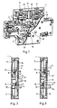
- the auxiliary switch arrangement has a housing 1 which the arrangement closes to the outside. In the housing 1 are visible in Fig.1 Fixed contact pieces 2, 3, 4 attached. The fixed contact pieces 2, 3, 4 are with the terminals 5, 6, 7, 8 of the auxiliary switch in an electrically conductive connection. The fixed contact pieces 2 and 3 and 4 and not in Fig.1 visible, are in the switched-on position with the contact bridges 9, 10 with each other connected.
- the contact bridges 9, 10 are U-shaped at one end bent leaf spring bands 11 are formed, as in Figures 4, 5 and 6th can be seen. The other ends 12 of the leaf spring bands 11 are in the housing 1 attached.
- the leaf spring strips 11 bring in the contact-making closed position the contact bridges 9, 10 the contact pressure, because they are by the amount of Contact pressure are biased.
- the leaf spring strips 11 protrude between the two end regions of the contact bridges 9, 10 beyond the contact bridges 9, 10, the outstanding ones Parts are formed into sliding brackets 13.
- This slide bracket 13 serve the Contact bridges 9, 10 to lift off the fixed contact pieces 2, 3, 4 and the Bring the auxiliary switch to the off position.
- the auxiliary switch assembly is equipped with a slide 14 which in Housing 1 is held and guided longitudinally.
- This slider 14 is provided with a linear cam 15. 2 shows the slide 14 in the upper position. In this position it is clearly visible that the cam 15 underneath the slide bracket 13 of the upper contact bridge 9 is pushed. This contact bridge 9 is thus lifted off the fixed contact pieces 2 and 3, the connection between terminals 5 and 6 is interrupted.
- the lower Slide bracket 13 is free, the contact bridge 10 is with the fixed contact pieces 4th in connection, the connection terminals 7 and 8 are electrically connected.
- FIG. 3 shows the auxiliary switch arrangement with the slide 14 pushed downward.
- the fixed contact pieces 2, 3 are connected because of the slide bracket 13 of the upper leaf spring band 11 is free and the contact bridge 9 on the Fixed contact pieces 2, 3 can rest.
- the contact pressure results from the Preload of the leaf spring band 11.
- the slide 14 is with an extension 16 provided that shifted by an electrical switching device, not shown can be.
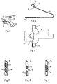
- the one-piece leaf spring band 11 is alone in FIGS. 4, 5 and 6 shown. In Figure 4 and also in Figure 6 are attached to the leaf spring band 11 movable contact pieces 17 particularly visible.
- FIG. 7 shows the slide 14 with differently arranged Cams 15, 18, 19, 20, 21. Due to the different designs of the cams 15, 18, 19, 20, 21, the closing and / or opening contacts as required to get voted.
- the cams 18, 19 shown in FIG. 7 actuate two Opener contacts, the cams 20, 21 visible in FIG. 8 have two make contacts.
- the cams 15 shown in FIG. 9 serve to actuate an opener and a make contact.
Landscapes
- Physics & Mathematics (AREA)
- Electromagnetism (AREA)
- Slide Switches (AREA)
- Contacts (AREA)
- Oscillators With Electromechanical Resonators (AREA)
- Supplying Of Containers To The Packaging Station (AREA)
- Push-Button Switches (AREA)
- Coupling Device And Connection With Printed Circuit (AREA)
- Measurement And Recording Of Electrical Phenomena And Electrical Characteristics Of The Living Body (AREA)
- Control Of Motors That Do Not Use Commutators (AREA)
- Control Of Eletrric Generators (AREA)
- Vehicle Body Suspensions (AREA)
Description
- Fig.1
- eine Hilfsschalteranordnung in perspektivischen Darstellung, teilweise im Schnitt,
- Fig.2
- von der Seite im Schnitt mit einem Schieber in der oberen Stellung,
- Fig.3
- in der unteren Stellung,
- Fig.4
- ein Blattfederband in perspektivischer Darstellung,
- Fig.5
- in Seitenriss,
- Fig.6
- in Aufriss,
- Fig.7 bis 9
- einen Schieber mit unterschiedlich angeordneten Nocken, in perspektivischer Darstellung.
Claims (2)
- Hilfsschalteranordnung mit mindestens zwei in einem Gehäuse (1) befestigten Festkontaktstücken (2, 3, 4) und mit mindestens einer mit den Festkontaktslücken (2, 3, 4) durch Verschiebung eines mit linearen Nocken (15, 18, 19, 20, 21) versehenen Schiebers (14) in und ausser Eingriff bringbaren, in Schliessrichtung federbelasteten Kontaktbrücke (9, 10), die am Ende eines sie tragenden Blattfederbandes quer zu seiner Längsrichtung liegt und die in der Trennstellung durch die Nocken (15, 18, 19, 20, 21) des Schiebers (14) von den Festkontaktstücken (2, 3, 4) abgehoben ist, wobei das Blattfederband (11) in kontaktgebender Schliesstellung der Kontaktbrücke (9, 10) um den Betrag des Kontaktdruckes vorgespannt ist dadurch gekennzeichnet, dass mehrere Kontaktbrücken (9, 10) und ein gemeinsamer Schieber (14) mit mehreren unterschiedlick ausgebildeten, jeweils zu jeder Kontaktbrücke (9, 10) zugeordneten Nocken (15, 18, 19, 20, 21) vorgesehen sind, wobei jede Kontaktbrücke (9, 10) am einen Ende eines zugeordneten U-förmig gebogenen Blattfederbandes (11) quer zur Längsrichtung des Blattfederbandes (11) einstückig angeformt und das andere, freie Ende (12) des U-förmig gebogenen, nicht stromführenden Blattfederbandes (11) im Gehäuse (1) befestigt ist.
- Hilfsschalteranordnung nach Anspruch 1, dadurch gekennzeichnet, dass das Blattfederband (11) zwischen den beiden auf den beiden Endbereichen der Kontaktbrücke (9, 10) angebrachten beweglichen Kontaktstücken (17) über die Kontaktbrücke (9, 10) hinausragt, wobei der überragende Teil zu einem mit den Nocken (15, 18, 19, 20, 21) des Schiebers (14) zusammenwirkenden Gleitbügel (13) geformt ist.
Applications Claiming Priority (3)
| Application Number | Priority Date | Filing Date | Title |
|---|---|---|---|
| CH2113/97 | 1997-09-09 | ||
| CH211397 | 1997-09-09 | ||
| CH211397 | 1997-09-09 |
Publications (3)
| Publication Number | Publication Date |
|---|---|
| EP0902447A2 EP0902447A2 (de) | 1999-03-17 |
| EP0902447A3 EP0902447A3 (de) | 2000-01-12 |
| EP0902447B1 true EP0902447B1 (de) | 2003-06-25 |
Family
ID=4226185
Family Applications (1)
| Application Number | Title | Priority Date | Filing Date |
|---|---|---|---|
| EP98108571A Expired - Lifetime EP0902447B1 (de) | 1997-09-09 | 1998-05-12 | Hilfsschalteranordnung |
Country Status (7)
| Country | Link |
|---|---|
| US (1) | US5927485A (de) |
| EP (1) | EP0902447B1 (de) |
| AT (1) | ATE243883T1 (de) |
| DE (1) | DE59808798D1 (de) |
| DK (1) | DK0902447T3 (de) |
| ES (1) | ES2196423T3 (de) |
| PT (1) | PT902447E (de) |
Families Citing this family (3)
| Publication number | Priority date | Publication date | Assignee | Title |
|---|---|---|---|---|
| JP4546639B2 (ja) * | 2000-12-06 | 2010-09-15 | ナイルス株式会社 | インヒビタースイッチ |
| US6534737B1 (en) | 2002-02-19 | 2003-03-18 | Onan Corporation | Contact closing speed limiter for a transfer switch |
| CN111180224B (zh) * | 2019-09-26 | 2021-11-09 | 胡建强 | 一种高可靠性的断火限位器 |
Family Cites Families (11)
| Publication number | Priority date | Publication date | Assignee | Title |
|---|---|---|---|---|
| US3249725A (en) * | 1963-05-23 | 1966-05-03 | Gen Electric | Electric switch with pressure lock terminals |
| GB1282654A (en) * | 1970-04-02 | 1972-07-19 | Mte Components Ltd | Improvements in or relating to electrical relays |
| US3715545A (en) * | 1971-06-18 | 1973-02-06 | Cherry Electrical Prod | Momentary push button switch with improved non-conductive cam for normally retaining movable leaf spring contacts in a non-operative position |
| US3787653A (en) * | 1971-11-24 | 1974-01-22 | Mossman D Inc | Electrical switch assembly |
| US3770921A (en) * | 1972-06-12 | 1973-11-06 | L Wilbrecht | Snap-action switch |
| US4331844A (en) * | 1980-02-29 | 1982-05-25 | Shigeru Saitoh | Electric switch device |
| US4366351A (en) * | 1980-11-07 | 1982-12-28 | Re-Al, Inc. | Electrical slide switch of flush through design and method of mounting thereof |
| US4395609A (en) * | 1981-07-24 | 1983-07-26 | General Motors Corporation | Cam operated dual switch assembly |
| DE3608703A1 (de) * | 1986-03-15 | 1987-09-24 | Siedle & Soehne S | Schaltelement |
| IT213976Z2 (it) * | 1988-06-23 | 1990-03-05 | Cge Spa | Struttura di contatti elettrici nella quale la forza assiale di azionamento e' solo una piccola frazione della forza esercitata sui contatti. |
| US4885435A (en) * | 1988-12-23 | 1989-12-05 | Telephone And Telegraph Company | Cantilever spring switch having multiple fulcrums |
-
1998
- 1998-04-09 US US09/058,168 patent/US5927485A/en not_active Expired - Lifetime
- 1998-05-12 DK DK98108571T patent/DK0902447T3/da active
- 1998-05-12 EP EP98108571A patent/EP0902447B1/de not_active Expired - Lifetime
- 1998-05-12 PT PT98108571T patent/PT902447E/pt unknown
- 1998-05-12 DE DE59808798T patent/DE59808798D1/de not_active Expired - Lifetime
- 1998-05-12 AT AT98108571T patent/ATE243883T1/de not_active IP Right Cessation
- 1998-05-12 ES ES98108571T patent/ES2196423T3/es not_active Expired - Lifetime
Also Published As
| Publication number | Publication date |
|---|---|
| DK0902447T3 (da) | 2003-08-18 |
| ATE243883T1 (de) | 2003-07-15 |
| DE59808798D1 (de) | 2003-07-31 |
| ES2196423T3 (es) | 2003-12-16 |
| PT902447E (pt) | 2003-11-28 |
| EP0902447A2 (de) | 1999-03-17 |
| US5927485A (en) | 1999-07-27 |
| EP0902447A3 (de) | 2000-01-12 |
Similar Documents
| Publication | Publication Date | Title |
|---|---|---|
| DE3411275A1 (de) | Leistungsschalter | |
| DE4408481C2 (de) | Sitzplatte, insbesondere für den Fahrersitz eines Nutzfahrzeuges | |
| EP2131377A1 (de) | Relais mit Doppel-Ankerwippe | |
| DE2740902A1 (de) | Elektrischer schalter | |
| EP2393097B1 (de) | Schalter mit selbstjustierender Schaltstößelführung | |
| EP0902447B1 (de) | Hilfsschalteranordnung | |
| DE19526591A1 (de) | Elektrischer Schalter | |
| DE7426189U (de) | HilfGeschalter-Anbauteil für Leitungsschutzschalter | |
| DE19642744C2 (de) | Schaltervorrichtung | |
| EP0884747A2 (de) | Installationsschaltgerät | |
| EP0068483B1 (de) | Elektromechanische Schalteinrichtung für Fernsprechgeräte | |
| DE2732723C2 (de) | Elektrische Schaltvorrichtung | |
| EP1440455B1 (de) | Elektrischer schalter | |
| DE3008756C2 (de) | Verriegelungsvorrichtung für eine Haushaltsmaschine o.dgl. | |
| EP1271583A2 (de) | Mehrpoliges Schaltgerät für den Einsatz auf Sammelschienensystemen | |
| EP0593077B1 (de) | Geräteschalter | |
| DE2547278A1 (de) | Elektrischer schnappschalter | |
| DE3331900C2 (de) | Vorrichtung zum Übertragen einer Betätigungsbewegung auf einen mehrpoligen Kontaktfedersatz | |
| EP0518179B1 (de) | Elektrischer Schalter | |
| DE69106218T2 (de) | Handzubetätigender Schutzschalter. | |
| EP0611481B1 (de) | Elektrischer schalter | |
| EP1054421A2 (de) | Schalter | |
| EP0508298A2 (de) | Schiebeschalter | |
| EP1174893B1 (de) | Elektrischer Schalter | |
| DE2808766C2 (de) | Elektrischer Schalter |
Legal Events
| Date | Code | Title | Description |
|---|---|---|---|
| PUAI | Public reference made under article 153(3) epc to a published international application that has entered the european phase |
Free format text: ORIGINAL CODE: 0009012 |
|
| AK | Designated contracting states |
Kind code of ref document: A2 Designated state(s): AT BE CH CY DE DK ES FI FR GB GR IE IT LI LU MC NL PT SE |
|
| AX | Request for extension of the european patent |
Free format text: AL;LT;LV;MK;RO;SI |
|
| PUAL | Search report despatched |
Free format text: ORIGINAL CODE: 0009013 |
|
| AK | Designated contracting states |
Kind code of ref document: A3 Designated state(s): AT BE CH CY DE DK ES FI FR GB GR IE IT LI LU MC NL PT SE |
|
| AX | Request for extension of the european patent |
Free format text: AL;LT;LV;MK;RO;SI |
|
| 17P | Request for examination filed |
Effective date: 20000712 |
|
| AKX | Designation fees paid |
Free format text: AT BE CH CY DE DK ES FI FR GB GR IE IT LI LU MC NL PT SE |
|
| 17Q | First examination report despatched |
Effective date: 20011115 |
|
| GRAH | Despatch of communication of intention to grant a patent |
Free format text: ORIGINAL CODE: EPIDOS IGRA |
|
| GRAH | Despatch of communication of intention to grant a patent |
Free format text: ORIGINAL CODE: EPIDOS IGRA |
|
| GRAA | (expected) grant |
Free format text: ORIGINAL CODE: 0009210 |
|
| AK | Designated contracting states |
Designated state(s): AT BE CH CY DE DK ES FI FR GB GR IE IT LI LU MC NL PT SE |
|
| PG25 | Lapsed in a contracting state [announced via postgrant information from national office to epo] |
Ref country code: CY Free format text: LAPSE BECAUSE OF FAILURE TO SUBMIT A TRANSLATION OF THE DESCRIPTION OR TO PAY THE FEE WITHIN THE PRESCRIBED TIME-LIMIT Effective date: 20030625 |
|
| REG | Reference to a national code |
Ref country code: GB Ref legal event code: FG4D Free format text: NOT ENGLISH |
|
| REG | Reference to a national code |
Ref country code: CH Ref legal event code: EP |
|
| REG | Reference to a national code |
Ref country code: SE Ref legal event code: TRGR |
|
| REG | Reference to a national code |
Ref country code: CH Ref legal event code: NV Representative=s name: MORVA PATENTDIENSTE |
|
| GBT | Gb: translation of ep patent filed (gb section 77(6)(a)/1977) | ||
| REG | Reference to a national code |
Ref country code: IE Ref legal event code: FG4D Free format text: GERMAN |
|
| REF | Corresponds to: |
Ref document number: 59808798 Country of ref document: DE Date of ref document: 20030731 Kind code of ref document: P |
|
| REG | Reference to a national code |
Ref country code: DK Ref legal event code: T3 |
|
| REG | Reference to a national code |
Ref country code: GR Ref legal event code: EP Ref document number: 20030403148 Country of ref document: GR |
|
| REG | Reference to a national code |
Ref country code: ES Ref legal event code: FG2A Ref document number: 2196423 Country of ref document: ES Kind code of ref document: T3 |
|
| ET | Fr: translation filed | ||
| PGFP | Annual fee paid to national office [announced via postgrant information from national office to epo] |
Ref country code: MC Payment date: 20040415 Year of fee payment: 7 |
|
| PGFP | Annual fee paid to national office [announced via postgrant information from national office to epo] |
Ref country code: PT Payment date: 20040419 Year of fee payment: 7 |
|
| PGFP | Annual fee paid to national office [announced via postgrant information from national office to epo] |
Ref country code: IE Payment date: 20040421 Year of fee payment: 7 |
|
| PGFP | Annual fee paid to national office [announced via postgrant information from national office to epo] |
Ref country code: GR Payment date: 20040423 Year of fee payment: 7 |
|
| PGFP | Annual fee paid to national office [announced via postgrant information from national office to epo] |
Ref country code: NL Payment date: 20040429 Year of fee payment: 7 |
|
| PLBE | No opposition filed within time limit |
Free format text: ORIGINAL CODE: 0009261 |
|
| STAA | Information on the status of an ep patent application or granted ep patent |
Free format text: STATUS: NO OPPOSITION FILED WITHIN TIME LIMIT |
|
| PGFP | Annual fee paid to national office [announced via postgrant information from national office to epo] |
Ref country code: LU Payment date: 20040504 Year of fee payment: 7 |
|
| PGFP | Annual fee paid to national office [announced via postgrant information from national office to epo] |
Ref country code: AT Payment date: 20040505 Year of fee payment: 7 Ref country code: FI Payment date: 20040505 Year of fee payment: 7 Ref country code: DK Payment date: 20040505 Year of fee payment: 7 |
|
| PGFP | Annual fee paid to national office [announced via postgrant information from national office to epo] |
Ref country code: BE Payment date: 20040608 Year of fee payment: 7 |
|
| 26N | No opposition filed |
Effective date: 20040326 |
|
| PG25 | Lapsed in a contracting state [announced via postgrant information from national office to epo] |
Ref country code: FI Free format text: LAPSE BECAUSE OF NON-PAYMENT OF DUE FEES Effective date: 20050506 |
|
| PG25 | Lapsed in a contracting state [announced via postgrant information from national office to epo] |
Ref country code: LU Free format text: LAPSE BECAUSE OF NON-PAYMENT OF DUE FEES Effective date: 20050512 Ref country code: IE Free format text: LAPSE BECAUSE OF NON-PAYMENT OF DUE FEES Effective date: 20050512 Ref country code: AT Free format text: LAPSE BECAUSE OF NON-PAYMENT OF DUE FEES Effective date: 20050512 |
|
| PG25 | Lapsed in a contracting state [announced via postgrant information from national office to epo] |
Ref country code: MC Free format text: LAPSE BECAUSE OF NON-PAYMENT OF DUE FEES Effective date: 20050531 Ref country code: DK Free format text: LAPSE BECAUSE OF NON-PAYMENT OF DUE FEES Effective date: 20050531 Ref country code: BE Free format text: LAPSE BECAUSE OF NON-PAYMENT OF DUE FEES Effective date: 20050531 |
|
| PG25 | Lapsed in a contracting state [announced via postgrant information from national office to epo] |
Ref country code: PT Free format text: LAPSE BECAUSE OF NON-PAYMENT OF DUE FEES Effective date: 20051114 |
|
| BERE | Be: lapsed |
Owner name: *ROCKWELL AUTOMATION A.G. Effective date: 20050531 |
|
| PG25 | Lapsed in a contracting state [announced via postgrant information from national office to epo] |
Ref country code: NL Free format text: LAPSE BECAUSE OF NON-PAYMENT OF DUE FEES Effective date: 20051201 |
|
| PG25 | Lapsed in a contracting state [announced via postgrant information from national office to epo] |
Ref country code: GR Free format text: LAPSE BECAUSE OF NON-PAYMENT OF DUE FEES Effective date: 20051205 |
|
| NLV4 | Nl: lapsed or anulled due to non-payment of the annual fee |
Effective date: 20051201 |
|
| REG | Reference to a national code |
Ref country code: IE Ref legal event code: MM4A |
|
| REG | Reference to a national code |
Ref country code: DK Ref legal event code: EBP |
|
| PGFP | Annual fee paid to national office [announced via postgrant information from national office to epo] |
Ref country code: CH Payment date: 20061025 Year of fee payment: 9 |
|
| BERE | Be: lapsed |
Owner name: *ROCKWELL AUTOMATION A.G. Effective date: 20050531 |
|
| REG | Reference to a national code |
Ref country code: CH Ref legal event code: PL |
|
| PG25 | Lapsed in a contracting state [announced via postgrant information from national office to epo] |
Ref country code: CH Free format text: LAPSE BECAUSE OF NON-PAYMENT OF DUE FEES Effective date: 20070531 Ref country code: LI Free format text: LAPSE BECAUSE OF NON-PAYMENT OF DUE FEES Effective date: 20070531 |
|
| REG | Reference to a national code |
Ref country code: DE Ref legal event code: R082 Ref document number: 59808798 Country of ref document: DE Representative=s name: GRUENECKER PATENT- UND RECHTSANWAELTE PARTG MB, DE |
|
| REG | Reference to a national code |
Ref country code: FR Ref legal event code: PLFP Year of fee payment: 18 |
|
| PGFP | Annual fee paid to national office [announced via postgrant information from national office to epo] |
Ref country code: ES Payment date: 20150526 Year of fee payment: 18 Ref country code: SE Payment date: 20150528 Year of fee payment: 18 Ref country code: GB Payment date: 20150527 Year of fee payment: 18 Ref country code: DE Payment date: 20150528 Year of fee payment: 18 |
|
| PGFP | Annual fee paid to national office [announced via postgrant information from national office to epo] |
Ref country code: IT Payment date: 20150527 Year of fee payment: 18 Ref country code: FR Payment date: 20150519 Year of fee payment: 18 |
|
| REG | Reference to a national code |
Ref country code: FR Ref legal event code: CJ Effective date: 20160705 Ref country code: FR Ref legal event code: CD Owner name: ROCKWELL AUTOMATION SWITZERLAND GMBH Effective date: 20160705 |
|
| REG | Reference to a national code |
Ref country code: ES Ref legal event code: PC2A Owner name: ROCKWELL AUTOMATION SWITZERLAND GMBH Effective date: 20160804 |
|
| REG | Reference to a national code |
Ref country code: FR Ref legal event code: CA Effective date: 20160708 |
|
| REG | Reference to a national code |
Ref country code: DE Ref legal event code: R082 Ref document number: 59808798 Country of ref document: DE Representative=s name: GRUENECKER PATENT- UND RECHTSANWAELTE PARTG MB, DE Ref country code: DE Ref legal event code: R081 Ref document number: 59808798 Country of ref document: DE Owner name: ROCKWELL AUTOMATION SWITZERLAND GMBH, CH Free format text: FORMER OWNER: ROCKWELL AUTOMATION AG, AARAU, CH |
|
| REG | Reference to a national code |
Ref country code: DE Ref legal event code: R119 Ref document number: 59808798 Country of ref document: DE |
|
| GBPC | Gb: european patent ceased through non-payment of renewal fee |
Effective date: 20160512 |
|
| PG25 | Lapsed in a contracting state [announced via postgrant information from national office to epo] |
Ref country code: IT Free format text: LAPSE BECAUSE OF NON-PAYMENT OF DUE FEES Effective date: 20160512 Ref country code: SE Free format text: LAPSE BECAUSE OF NON-PAYMENT OF DUE FEES Effective date: 20160513 |
|
| REG | Reference to a national code |
Ref country code: FR Ref legal event code: ST Effective date: 20170131 |
|
| PG25 | Lapsed in a contracting state [announced via postgrant information from national office to epo] |
Ref country code: DE Free format text: LAPSE BECAUSE OF NON-PAYMENT OF DUE FEES Effective date: 20161201 Ref country code: FR Free format text: LAPSE BECAUSE OF NON-PAYMENT OF DUE FEES Effective date: 20160531 |
|
| PG25 | Lapsed in a contracting state [announced via postgrant information from national office to epo] |
Ref country code: GB Free format text: LAPSE BECAUSE OF NON-PAYMENT OF DUE FEES Effective date: 20160512 |
|
| PG25 | Lapsed in a contracting state [announced via postgrant information from national office to epo] |
Ref country code: ES Free format text: LAPSE BECAUSE OF NON-PAYMENT OF DUE FEES Effective date: 20160513 |
|
| REG | Reference to a national code |
Ref country code: ES Ref legal event code: FD2A Effective date: 20180622 |