EP0902349A2 - Handkurbel - Google Patents
Handkurbel Download PDFInfo
- Publication number
- EP0902349A2 EP0902349A2 EP98117375A EP98117375A EP0902349A2 EP 0902349 A2 EP0902349 A2 EP 0902349A2 EP 98117375 A EP98117375 A EP 98117375A EP 98117375 A EP98117375 A EP 98117375A EP 0902349 A2 EP0902349 A2 EP 0902349A2
- Authority
- EP
- European Patent Office
- Prior art keywords
- section
- shaft
- hand crank
- input shaft
- sections
- Prior art date
- Legal status (The legal status is an assumption and is not a legal conclusion. Google has not performed a legal analysis and makes no representation as to the accuracy of the status listed.)
- Withdrawn
Links
- 210000003205 muscle Anatomy 0.000 description 1
Images
Classifications
-
- F—MECHANICAL ENGINEERING; LIGHTING; HEATING; WEAPONS; BLASTING
- F16—ENGINEERING ELEMENTS AND UNITS; GENERAL MEASURES FOR PRODUCING AND MAINTAINING EFFECTIVE FUNCTIONING OF MACHINES OR INSTALLATIONS; THERMAL INSULATION IN GENERAL
- F16C—SHAFTS; FLEXIBLE SHAFTS; ELEMENTS OR CRANKSHAFT MECHANISMS; ROTARY BODIES OTHER THAN GEARING ELEMENTS; BEARINGS
- F16C3/00—Shafts; Axles; Cranks; Eccentrics
- F16C3/04—Crankshafts, eccentric-shafts; Cranks, eccentrics
- F16C3/22—Cranks; Eccentrics
-
- B—PERFORMING OPERATIONS; TRANSPORTING
- B60—VEHICLES IN GENERAL
- B60S—SERVICING, CLEANING, REPAIRING, SUPPORTING, LIFTING, OR MANOEUVRING OF VEHICLES, NOT OTHERWISE PROVIDED FOR
- B60S9/00—Ground-engaging vehicle fittings for supporting, lifting, or manoeuvring the vehicle, wholly or in part, e.g. built-in jacks
- B60S9/02—Ground-engaging vehicle fittings for supporting, lifting, or manoeuvring the vehicle, wholly or in part, e.g. built-in jacks for only lifting or supporting
- B60S9/04—Ground-engaging vehicle fittings for supporting, lifting, or manoeuvring the vehicle, wholly or in part, e.g. built-in jacks for only lifting or supporting mechanically
- B60S9/06—Ground-engaging vehicle fittings for supporting, lifting, or manoeuvring the vehicle, wholly or in part, e.g. built-in jacks for only lifting or supporting mechanically of screw-and-nut type
- B60S9/08—Ground-engaging vehicle fittings for supporting, lifting, or manoeuvring the vehicle, wholly or in part, e.g. built-in jacks for only lifting or supporting mechanically of screw-and-nut type the screw axis being substantially vertical
Definitions
- Hand cranks are used to drive various devices and devices used. In many cases this is about lifting and lowering loads of different types with winches, jacks, Support of semitrailers or the like.
- Such lifting device can although have a suitable gear ratio that the by Muscle strength increases maximum load, however, this requires a large one Number of crank revolutions.
- the object of the invention is therefore to create a hand crank, in a position with a large lever arm for lifting loads and one further position with a small lever arm for faster rotation load-free operation is applicable.
- Such a hand crank can on the one hand with its shaft section the input shaft of the device.
- the Hand crank turned using the handle section.
- She has a big one Lever arm that allows loads to be lifted.
- the Shaft section are attached to the input shaft so that the extension the geometric axis of the input shaft parallel to the axes of the two inclined intermediate sections and in the middle between them runs.
- the two intermediate sections can handle form the crank, which is only in relation to the shaft section have a short lever arm, but allow a relatively quick turn.
- the angle at which both intermediate sections with the adjacent sections are connected 45 °.
- the wave section can also be swiveled by approx. 45 ° with respect to the input shaft or can be switched between the two angular positions.
- the input shaft and the shaft section preferably have a positive fit interacting profile sections, such as an outer square the input shaft and an inner square on the shaft section.
- the hand crank can be installed or fixed on the input shaft also be removable. You can also after use in a Rest position can be folded down.
- two are at an angle to each other Profile sections with the end of the shaft section and with each other connected.
- One of the profile sections is aligned with the axis of the shaft section, while the other is inclined at 45 ° to the shaft section is.
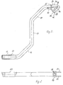
- the hand crank As can be seen from the drawing, there is the hand crank according to the invention First of all from the elements that are usual with hand cranks, namely one Shaft section 10, a parallel and at a distance from this and the rest longitudinally offset handle section 12 and a perpendicular to both, connecting both in a Z arrangement Lever section 14. In contrast to conventional hand cranks extends this lever section does not extend directly to the other two Sections 10.12. Rather, the three sections above are about obliquely arranged intermediate sections 16, 18 connected, namely in the shown example at 45 °.
- a rotatable sleeve 20 for gripping is located on the handle section 12 with the hand.
- One of the two Partial surfaces 24 are butted in front of the end of the shaft section 10, while the other, as shown in the drawing, obliquely from the end of the Projecting shaft section.
- There is one in both partial areas 24, 26 Recess in the form of an inner square 28, as shown in FIG. 2. This inner square 28 allows the reception of a shaft with an outer square profile, as will be explained in more detail later. Unless the hand crank is off Tube material, this shaft can pass through the inner square of the other Enter partial surface 24 into the interior of shaft section 10.
- the hand crank is provided for connection to a not shown Input shaft of a device to be driven, which, based on the illustrated Example, has an outer square cross-section that the inner square 28 corresponds. On opposite outer sides of this outer square there are projecting pins, not shown, which fit into the slot 38 cheeks 30,32 enter.
- the crank handle can either with its shaft section on the input shaft be pushed onto the recess in the square socket 28 occurs.
- the pin not shown, moves into one of the legs 40, 42 in the direction of the corresponding surface 24, 26 to at the end of the leg 40.42.
- the interlocking interlocking parts separate Profile areas of the hand crank and the input shaft from each other. in the the rest of the pin moves to the apex of the V-shaped slot 38. In this position the hand crank can be swiveled by 45 ° and then be pushed onto the input shaft until the positive Connection is established in the new angular position.
- While the hand crank is in the one angular position like a normal one Hand crank can be moved with a relatively large lever arm, it will in the other angular position for a quick, smooth rotation with used with both hands.
Landscapes
- Engineering & Computer Science (AREA)
- Mechanical Engineering (AREA)
- General Engineering & Computer Science (AREA)
- Ocean & Marine Engineering (AREA)
- Transmission Devices (AREA)
- Details Of Rigid Or Semi-Rigid Containers (AREA)
- Steering Devices For Bicycles And Motorcycles (AREA)
- Table Equipment (AREA)
- Dry Shavers And Clippers (AREA)
- Micromachines (AREA)
- Massaging Devices (AREA)
Abstract
Description
- einem mit einer Eingangswelle eines durch die Handkurbel angetriebenen Geräts verbundenen oder verbindbaren Wellenabschnitt
- einem parallel zu diesem gerichteten und in Längsrichtung versetzt angeordneten Handgriffabschnitt, und
- einem den Wellenabschnitt und den Handgriffabschnitt in rechtwinklig-Z-förmiger Anordnung verbindenden Hebelabschnitt.
- Fig. 1
- ist eine schematische Seitenansicht einer erfindungsgemäßen Handkurbel;
- Fig. 2
- zeigt eine Draufsicht zu Fig. 1.
Claims (7)
- Handkurbel mit:einem mit einer Eingangswelle eines durch die Handkurbel angetriebenen Geräts verbundenen oder verbindbaren Wellenabschnitt (10),einem parallel zu diesem gerichteten und in Längsrichtung versetzt angeordneten Handgriffabschnitt (12), undeinem den Wellenabschnitt (10) und den Handgriffabschnitt (12) in rechtwinklig-Z-förmiger Anordnung verbindenden Hebelabschnitt (14), dadurch gekennzeichnet, daß der Wellenabschnitt (10) mit der Eingangswelle drehfest, aber wenigstens in der Ebene der Handkurbel schwenkbar verbunden oder verbindbar ist, und daß zwischen dem Wellenabschnitt (10) und dem Hebelabschnitt (14) einerseits und diesem und dem Handgriffabschnitt (12) andererseits zu beiden angrenzenden Abschnitten schräg verlaufende Zwischenabschnitte (16,18) vorgesehen sind.
- Handkurbel nach Anspruch 1, dadurch gekennzeichnet, daß die Zwischenabschnitte (16,18) im wesentlichen unter 45° zu den beiden angrenzenden Abschnitten (10,12,14) verlaufen.
- Handkurbel nach Anspruch 1 oder 2, dadurch gekennzeichnet, daß der Wellenabschnitt (10) und die Eingangswelle in Drehrichtung formschlüssig ineinander greifende Profilabschnitte aufweisen.
- Handkurbel nach Anspruch 3, dadurch gekennzeichnet, daß die Eingangswelle ein Außenvierkantprofil und der Wellenabschnitt (10) ein Innenvierkantprofil (28) aufweist.
- Handkurbel nach einem der vorhergehenden Ansprüche, dadurch gekennzeichnet, daß der Wellenabschnitt (10) in bezug auf die Eingangswelle wenigstens zwischen einem Winkel, bei dem der Wellenabschnitt (10) koaxial zur Eingangswelle liegt, und einem Winkel, bei dem die geometrische Achse der Eingangswelle parallel zwischen den Achsen der beiden Zwischenabschnitte (16,18) und in gleichem Abstand zu beiden verläuft, schwenkbar ist.
- Handkurbel nach einem der Ansprüche 3 bis 5, dadurch gekennzeichnet, daß der Wellenabschnitt (10) an seinem freien Ende einen koaxial zum Wellenabschnitt gerichteten und einen schräg zu diesem angeordneten, unrunden Profilabschnitt, insbesondere Innenvierkant aufweist.
- Handkurbel nach Anspruch 6, dadurch gekennzeichnet, daß in Verlängerung der Profilabschnitte zwei parallele Wangen (30,32) vorgesehen sind, in denen sich deckungsgleiche, V-förmige Schlitze (38) befinden, in denen Stifte auf gegenüberliegenden Seiten der Eingangswelle geführt sind, und daß die Schenkel (40,42) der Schlitze in die Richtung der beiden Verbindungsstellungen zwischen Wellenabschnitt (10) und Eingangswelle gerichtet sind.
Applications Claiming Priority (2)
| Application Number | Priority Date | Filing Date | Title |
|---|---|---|---|
| DE29716460U DE29716460U1 (de) | 1997-09-15 | 1997-09-15 | Handkurbel |
| DE29716460U | 1997-09-15 |
Publications (2)
| Publication Number | Publication Date |
|---|---|
| EP0902349A2 true EP0902349A2 (de) | 1999-03-17 |
| EP0902349A3 EP0902349A3 (de) | 2000-11-22 |
Family
ID=8045943
Family Applications (1)
| Application Number | Title | Priority Date | Filing Date |
|---|---|---|---|
| EP98117375A Withdrawn EP0902349A3 (de) | 1997-09-15 | 1998-09-14 | Handkurbel |
Country Status (2)
| Country | Link |
|---|---|
| EP (1) | EP0902349A3 (de) |
| DE (1) | DE29716460U1 (de) |
Family Cites Families (3)
| Publication number | Priority date | Publication date | Assignee | Title |
|---|---|---|---|---|
| FR660610A (fr) * | 1928-09-20 | 1929-07-13 | Tige pour commande des crics | |
| GB2213783A (en) * | 1987-12-17 | 1989-08-23 | Metallifacture Ltd | Adjustable length hand crank for jack |
| EP0623548A1 (de) * | 1993-05-03 | 1994-11-09 | Batz, S. Coop. Ltda. | Handkurbel für Wagenheber |
-
1997
- 1997-09-15 DE DE29716460U patent/DE29716460U1/de not_active Expired - Lifetime
-
1998
- 1998-09-14 EP EP98117375A patent/EP0902349A3/de not_active Withdrawn
Non-Patent Citations (1)
| Title |
|---|
| None |
Also Published As
| Publication number | Publication date |
|---|---|
| EP0902349A3 (de) | 2000-11-22 |
| DE29716460U1 (de) | 1997-12-11 |
Similar Documents
| Publication | Publication Date | Title |
|---|---|---|
| DE69702664T2 (de) | Vorrichtung zum transportieren von gegenständen | |
| DE2624429B2 (de) | Klemmittel | |
| DE9108825U1 (de) | Scherenhubtisch | |
| DE3886887T2 (de) | Gewindereparaturwerkzeug. | |
| EP0364728A1 (de) | Hebeklemme | |
| DE2141131A1 (de) | Stopfwerkzeug einer Gleisstopfmaschine | |
| DE4304992A1 (de) | Vorrichtung zum Spannen von Brettern, insbesondere Fußbodenbrettern | |
| EP0307565A1 (de) | Arbeitstisch mit verstellbarer Tischplatte | |
| DE202022100091U1 (de) | Beweglicher Arbeitstisch für eine Steinschneidemaschine | |
| EP0123022A1 (de) | Hub- bzw. Absetzvorrichtung für transportable Behälter, z.B. Kabinen, Container, Shelter oder dergleichen | |
| EP0902349A2 (de) | Handkurbel | |
| DE2049211B2 (de) | Greifvorrichtung für Bauteile | |
| DE69102057T2 (de) | Richtbank für fahrzeugkarosserie. | |
| DE29614399U1 (de) | Anschlußstück für den Tragrahmen eines Tisches | |
| DE2815845A1 (de) | Vorrichtung zum leichteren loesen festsitzender radschrauben und -muttern | |
| DE4312501A1 (de) | Arbeitsgestell | |
| DE29518407U1 (de) | Vorrichtung zur stückweisen Querzuführung langer Teile | |
| DE3233741C2 (de) | Gerät zum Verbinden von zwei stumpf gestoßenen Bewehrungsstäben mittels einer Muffe | |
| DE102015116685B3 (de) | Spannfutteraufnahmemittel | |
| DE2707397C2 (de) | Gehäuse für elektrische Geräte | |
| DE3544891A1 (de) | Elektrisches ruehrgeraet | |
| DE69402027T2 (de) | Kegelrad-Winkelgetrieb für Rolladen | |
| DE2458578C3 (de) | Handbohrmaschine | |
| DE3417584C1 (de) | Schnellspannvorrichtung | |
| DE3224540A1 (de) | Beschlag zum verstellen einer platte eines schreibtisches, eines schreibpultes od. dgl. |
Legal Events
| Date | Code | Title | Description |
|---|---|---|---|
| PUAI | Public reference made under article 153(3) epc to a published international application that has entered the european phase |
Free format text: ORIGINAL CODE: 0009012 |
|
| AK | Designated contracting states |
Kind code of ref document: A2 Designated state(s): AT BE CH CY DE DK ES FI FR GB GR IE IT LI LU MC NL PT SE |
|
| AX | Request for extension of the european patent |
Free format text: AL;LT;LV;MK;RO;SI |
|
| PUAL | Search report despatched |
Free format text: ORIGINAL CODE: 0009013 |
|
| AK | Designated contracting states |
Kind code of ref document: A3 Designated state(s): AT BE CH CY DE DK ES FI FR GB GR IE IT LI LU MC NL PT SE |
|
| AX | Request for extension of the european patent |
Free format text: AL;LT;LV;MK;RO;SI |
|
| RIC1 | Information provided on ipc code assigned before grant |
Free format text: 7G 05G 1/04 A, 7G 05G 1/08 B, 7B 66F 3/12 B |
|
| AKX | Designation fees paid | ||
| REG | Reference to a national code |
Ref country code: DE Ref legal event code: 8566 |
|
| STAA | Information on the status of an ep patent application or granted ep patent |
Free format text: STATUS: THE APPLICATION IS DEEMED TO BE WITHDRAWN |
|
| 18D | Application deemed to be withdrawn |
Effective date: 20010523 |