EP0902349A2 - Handle - Google Patents
Handle Download PDFInfo
- Publication number
- EP0902349A2 EP0902349A2 EP98117375A EP98117375A EP0902349A2 EP 0902349 A2 EP0902349 A2 EP 0902349A2 EP 98117375 A EP98117375 A EP 98117375A EP 98117375 A EP98117375 A EP 98117375A EP 0902349 A2 EP0902349 A2 EP 0902349A2
- Authority
- EP
- European Patent Office
- Prior art keywords
- section
- shaft
- hand crank
- input shaft
- sections
- Prior art date
- Legal status (The legal status is an assumption and is not a legal conclusion. Google has not performed a legal analysis and makes no representation as to the accuracy of the status listed.)
- Withdrawn
Links
- 210000003205 muscle Anatomy 0.000 description 1
Images
Classifications
-
- F—MECHANICAL ENGINEERING; LIGHTING; HEATING; WEAPONS; BLASTING
- F16—ENGINEERING ELEMENTS AND UNITS; GENERAL MEASURES FOR PRODUCING AND MAINTAINING EFFECTIVE FUNCTIONING OF MACHINES OR INSTALLATIONS; THERMAL INSULATION IN GENERAL
- F16C—SHAFTS; FLEXIBLE SHAFTS; ELEMENTS OR CRANKSHAFT MECHANISMS; ROTARY BODIES OTHER THAN GEARING ELEMENTS; BEARINGS
- F16C3/00—Shafts; Axles; Cranks; Eccentrics
- F16C3/04—Crankshafts, eccentric-shafts; Cranks, eccentrics
- F16C3/22—Cranks; Eccentrics
-
- B—PERFORMING OPERATIONS; TRANSPORTING
- B60—VEHICLES IN GENERAL
- B60S—SERVICING, CLEANING, REPAIRING, SUPPORTING, LIFTING, OR MANOEUVRING OF VEHICLES, NOT OTHERWISE PROVIDED FOR
- B60S9/00—Ground-engaging vehicle fittings for supporting, lifting, or manoeuvring the vehicle, wholly or in part, e.g. built-in jacks
- B60S9/02—Ground-engaging vehicle fittings for supporting, lifting, or manoeuvring the vehicle, wholly or in part, e.g. built-in jacks for only lifting or supporting
- B60S9/04—Ground-engaging vehicle fittings for supporting, lifting, or manoeuvring the vehicle, wholly or in part, e.g. built-in jacks for only lifting or supporting mechanically
- B60S9/06—Ground-engaging vehicle fittings for supporting, lifting, or manoeuvring the vehicle, wholly or in part, e.g. built-in jacks for only lifting or supporting mechanically of screw-and-nut type
- B60S9/08—Ground-engaging vehicle fittings for supporting, lifting, or manoeuvring the vehicle, wholly or in part, e.g. built-in jacks for only lifting or supporting mechanically of screw-and-nut type the screw axis being substantially vertical
Definitions
- Hand cranks are used to drive various devices and devices used. In many cases this is about lifting and lowering loads of different types with winches, jacks, Support of semitrailers or the like.
- Such lifting device can although have a suitable gear ratio that the by Muscle strength increases maximum load, however, this requires a large one Number of crank revolutions.
- the object of the invention is therefore to create a hand crank, in a position with a large lever arm for lifting loads and one further position with a small lever arm for faster rotation load-free operation is applicable.
- Such a hand crank can on the one hand with its shaft section the input shaft of the device.
- the Hand crank turned using the handle section.
- She has a big one Lever arm that allows loads to be lifted.
- the Shaft section are attached to the input shaft so that the extension the geometric axis of the input shaft parallel to the axes of the two inclined intermediate sections and in the middle between them runs.
- the two intermediate sections can handle form the crank, which is only in relation to the shaft section have a short lever arm, but allow a relatively quick turn.
- the angle at which both intermediate sections with the adjacent sections are connected 45 °.
- the wave section can also be swiveled by approx. 45 ° with respect to the input shaft or can be switched between the two angular positions.
- the input shaft and the shaft section preferably have a positive fit interacting profile sections, such as an outer square the input shaft and an inner square on the shaft section.
- the hand crank can be installed or fixed on the input shaft also be removable. You can also after use in a Rest position can be folded down.
- two are at an angle to each other Profile sections with the end of the shaft section and with each other connected.
- One of the profile sections is aligned with the axis of the shaft section, while the other is inclined at 45 ° to the shaft section is.
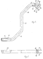
- the hand crank As can be seen from the drawing, there is the hand crank according to the invention First of all from the elements that are usual with hand cranks, namely one Shaft section 10, a parallel and at a distance from this and the rest longitudinally offset handle section 12 and a perpendicular to both, connecting both in a Z arrangement Lever section 14. In contrast to conventional hand cranks extends this lever section does not extend directly to the other two Sections 10.12. Rather, the three sections above are about obliquely arranged intermediate sections 16, 18 connected, namely in the shown example at 45 °.
- a rotatable sleeve 20 for gripping is located on the handle section 12 with the hand.
- One of the two Partial surfaces 24 are butted in front of the end of the shaft section 10, while the other, as shown in the drawing, obliquely from the end of the Projecting shaft section.
- There is one in both partial areas 24, 26 Recess in the form of an inner square 28, as shown in FIG. 2. This inner square 28 allows the reception of a shaft with an outer square profile, as will be explained in more detail later. Unless the hand crank is off Tube material, this shaft can pass through the inner square of the other Enter partial surface 24 into the interior of shaft section 10.
- the hand crank is provided for connection to a not shown Input shaft of a device to be driven, which, based on the illustrated Example, has an outer square cross-section that the inner square 28 corresponds. On opposite outer sides of this outer square there are projecting pins, not shown, which fit into the slot 38 cheeks 30,32 enter.
- the crank handle can either with its shaft section on the input shaft be pushed onto the recess in the square socket 28 occurs.
- the pin not shown, moves into one of the legs 40, 42 in the direction of the corresponding surface 24, 26 to at the end of the leg 40.42.
- the interlocking interlocking parts separate Profile areas of the hand crank and the input shaft from each other. in the the rest of the pin moves to the apex of the V-shaped slot 38. In this position the hand crank can be swiveled by 45 ° and then be pushed onto the input shaft until the positive Connection is established in the new angular position.
- While the hand crank is in the one angular position like a normal one Hand crank can be moved with a relatively large lever arm, it will in the other angular position for a quick, smooth rotation with used with both hands.
Landscapes
- Engineering & Computer Science (AREA)
- Mechanical Engineering (AREA)
- General Engineering & Computer Science (AREA)
- Ocean & Marine Engineering (AREA)
- Transmission Devices (AREA)
- Details Of Rigid Or Semi-Rigid Containers (AREA)
- Steering Devices For Bicycles And Motorcycles (AREA)
- Table Equipment (AREA)
- Dry Shavers And Clippers (AREA)
- Micromachines (AREA)
- Massaging Devices (AREA)
Abstract
Description
Die Erfindung betrifft eine Handkurbel mit:
- einem mit einer Eingangswelle eines durch die Handkurbel angetriebenen Geräts verbundenen oder verbindbaren Wellenabschnitt
- einem parallel zu diesem gerichteten und in Längsrichtung versetzt angeordneten Handgriffabschnitt, und
- einem den Wellenabschnitt und den Handgriffabschnitt in rechtwinklig-Z-förmiger Anordnung verbindenden Hebelabschnitt.
- a shaft section connected or connectable to an input shaft of a device driven by the hand crank
- a handle section directed parallel to this and offset in the longitudinal direction, and
- a lever section connecting the shaft section and the handle section in a rectangular Z-shaped arrangement.
Handkurbeln werden zum Antreiben von unterschiedlichen Geräten und Vorrichtungen verwendet. In vielen Fällen handelt es sich dabei um das Heben und Senken von Lasten unterschiedlicher Art mit Winden, Wagenhebern, Stützen von Sattelaufliegern oder dergleichen. Derartige Hubvorrichtung können zwar ein geeignetes Übersetzungsverhältnis aufweisen, das die durch Muskelkraft anhebbare maximale Last erhöht, jedoch erfordert dies eine große Anzahl von Kurbelumdrehungen.Hand cranks are used to drive various devices and devices used. In many cases this is about lifting and lowering loads of different types with winches, jacks, Support of semitrailers or the like. Such lifting device can although have a suitable gear ratio that the by Muscle strength increases maximum load, however, this requires a large one Number of crank revolutions.
Während somit beim Anheben einer Last eine große Anzahl von Kurbelumdrehungen unvermeidlich ist, erweist sich die Notwendigkeit der zahlreichen Umdrehungen beim Absenken einer Last oder bei lastfreiem Betrieb als lästig und zeitraubend.Thus, while lifting a load, a large number of crank revolutions is inevitable, the need for the numerous proves Revolutions when lowering a load or in load-free operation as troublesome and time consuming.
Der Erfindung liegt daher die Aufgabe zugrunde, eine Handkurbel zu schaffen, die in einer Stellung mit großem Hebelarm zum Anheben von Lasten und einer weiteren Stellung mit kleinem Hebelarm für eine raschere Drehung bei lastfreiem Betrieb anwendbar ist.The object of the invention is therefore to create a hand crank, in a position with a large lever arm for lifting loads and one further position with a small lever arm for faster rotation load-free operation is applicable.
Diese Aufgabe wird erfindungsgemäß bei einer Handkurbel der obigen Art dadurch gelöst, daß der Wellenabschnitt mit der Eingangswelle drehfest, aber wenigstens in der Ebene der Handkurbel schwenkbar verbunden oder verbindbar ist und daß zwischen dem Wellenabschnitt und dem Hebelabschnitt einerseits und diesem und dem Handgriffabschnitt andererseits zu beiden angrenzenden Abschnitten schräg verlaufende Zwischenabschnitte vorgesehen sind. This object is achieved according to the invention in a hand crank of the above type solved that the shaft section with the input shaft rotatably, but at least in the plane of the hand crank pivotally connected or connectable and that between the shaft portion and the lever portion on the one hand and this and the handle section on the other hand to both adjacent Sections sloping intermediate sections are provided are.
Eine derartige Handkurbel kann zum einen mit ihrem Wellenabschnitt mit der Eingangswelledes Geräts ausgerichtet werden. In diesem Falle wird die Handkurbel mit Hilfe des Handgriffabschnitts gedreht. Sie weist einen großen Hebelarm auf, der das Heben von Lasten gestattet. Andererseits kann der Wellenabschnitt derart an die Eingangswelle angesetzt werden, daß die Verlängerung der geometrischen Achse der Eingangswelle parallel zu den Achsen der beiden schrägen Zwischenabschnitte und in der Mitte zwischen diesen verläuft. In diesem Falle können die beiden Zwischenabschnitte Handgriffe der Kurbel bilden, die zwar im Verhältnis zu dem Wellenabschnitt nur einen kurzen Hebelarm besitzen, dafür aber eine relativ rasche Drehung ermöglichen.Such a hand crank can on the one hand with its shaft section the input shaft of the device. In this case the Hand crank turned using the handle section. She has a big one Lever arm that allows loads to be lifted. On the other hand, the Shaft section are attached to the input shaft so that the extension the geometric axis of the input shaft parallel to the axes of the two inclined intermediate sections and in the middle between them runs. In this case, the two intermediate sections can handle form the crank, which is only in relation to the shaft section have a short lever arm, but allow a relatively quick turn.
Vorzugsweise beträgt der Winkel, mit dem beide Zwischenabschnitte mit den angrenzenden Abschnitten verbunden sind, 45°. In diesem Fall ist der Wellenabschnitt in bezug auf die Eingangswelle ebenfalls um ca. 45° schwenkbar bzw. zwischen beiden Winkelstellungen umsteckbar. Es ist jedoch nicht unbedingt notwendig, die erwähnten Winkel auf 45° festzulegen. Je kleiner der Winkel zwischen den beiden Zwischenabschnitten und dem Wellenabschnitt einerseits sowie dem Handgriffabschnitt andererseits ist, desto größer wird der Hebelarm bei der zweiten Einsatzform der erfindungsgemäßen Handkurbel.Preferably, the angle at which both intermediate sections with the adjacent sections are connected, 45 °. In this case, the wave section can also be swiveled by approx. 45 ° with respect to the input shaft or can be switched between the two angular positions. However, it is not essential necessary to set the mentioned angles to 45 °. The smaller the Angle between the two intermediate sections and the shaft section on the one hand and the handle section on the other hand, the larger the lever arm in the second form of use of the hand crank according to the invention.
Die Eingangswelle und der Wellenabschnitt besitzen vorzugsweise formschlüssig zusammenwirkende Profilabschnitte, etwa einen Außenvierkant an der Eingangswelle und einen Innenvierkant am Wellenabschnitt.The input shaft and the shaft section preferably have a positive fit interacting profile sections, such as an outer square the input shaft and an inner square on the shaft section.
Wie üblich, kann die Handkurbel fest auf der Eingangswelle installiert oder auch abziehbar sein. Sie kann im übrigen auch nach dem Gebrauch in einer Ruhestellung abklappbar sein.As usual, the hand crank can be installed or fixed on the input shaft also be removable. You can also after use in a Rest position can be folded down.
Bei einer bevorzugten Ausführungsform sind zwei im Winkel zueinander stehende Profilabschnitte mit dem Ende des Wellenabschnitts und untereinander verbunden. Einer der Profilabschnitte fluchtet mit der Achse des Wellenabschnitts, während der andere unter 45° zu dem Wellenabschnitt geneigt ist. In a preferred embodiment, two are at an angle to each other Profile sections with the end of the shaft section and with each other connected. One of the profile sections is aligned with the axis of the shaft section, while the other is inclined at 45 ° to the shaft section is.
Auf gegenüberliegenden Seiten der beiden Profilabschnitte befinden sich zwei parallele, deckungsgleiche Wangen mit giebelförmigen Umriß. In diesen Wangen befinden sich in deckungsgleicher Anordnung V-förmige Schlitze, deren beide Schenkel in Achsrichtung der beiden Profilabschnitte gerichtet sind. In diesen Schlitzen befinden sich Stifte, die auf gegenüberliegenden Seite von der Eingangswelle des Geräts ausgehen. Der Wellenabschnitt kann daher in beiden Winkelstellungen mit dem jeweiligen Profilabschnitt bis zum formschlüssigen Eingriff der beiderseitigen Profilabschnitte vorgeschoben und auf der anderen Seite von der Eingangswelle abgezogen werden. Wenn die Stifte den Scheitelpunkt der V-förmigen Schlitze erreicht haben, kann die Handkurbel von der einen in die andere Winkelstellung geschwenkt werden.Are located on opposite sides of the two profile sections two parallel, congruent cheeks with a gable-shaped outline. In these Cheeks are congruently arranged V-shaped slots, whose two legs are directed in the axial direction of the two profile sections are. In these slots are pins that are on opposite Start from the input shaft of the device. The shaft section can therefore in both angular positions with the respective profile section up to positive engagement of the profile sections on both sides advanced and be subtracted from the input shaft on the other side. If the pins may have reached the apex of the V-shaped slots the crank handle can be swiveled from one angle to the other.
Im folgenden werden bevorzugte Ausführungsbeispiele der Erfindung anhand der beigefügten Zeichnung näher erläutert.
- Fig. 1
- ist eine schematische Seitenansicht einer erfindungsgemäßen Handkurbel;
- Fig. 2
- zeigt eine Draufsicht zu Fig. 1.
- Fig. 1
- is a schematic side view of a hand crank according to the invention;
- Fig. 2
- shows a top view of FIG. 1.
Wie aus der Zeichnung hervorgeht, besteht die erfindungsgemäße Handkurbel
zunächst aus den bei Handkurbeln üblichen Elementen, nämlich einem
Wellenabschnitt 10, einem parallel und in Abstand zu diesem und im übrigen
in Längsrichtung versetzt verlaufenden Handgriffabschnitt 12 und einem
senkrecht zu beiden verlaufenden, beide in einer Z-Anordnung verbindenden
Hebelabschnitt 14. Im Unterschied zu herkömmlichen Handkurbeln erstreckt
sich dieser Hebelabschnitt nicht unmittelbar bis zu den beiden anderen
Abschnitten 10,12. Vielmehr sind die drei genannten Abschnitte über
schräg angeordnete Zwischenabschnitte 16,18 verbunden, und zwar bei dem
dargestellten Beispiel jeweils unter 45°.As can be seen from the drawing, there is the hand crank according to the invention
First of all from the elements that are usual with hand cranks, namely one
Auf dem Handgriffabschnitt 12 befindet sich eine drehbar Hülse 20 zum Erfassen
mit der Hand. A
Am freien Ende des Wellenabschnitts 10 befindet sich eine gemäß Fig. 2
rechteckige Platte 22, die aus zwei miteinander verbundenen Teilflächen
24,26 besteht, die stumpfwinklig zueinander abgewinkelt sind, und zwar
beim dargestellten Ausführungbeispiel unter 180 - 45 = 135°. Eine der beiden
Teilflächen 24 ist stumpf vor das Ende des Wellenabschnitts 10 gesetzt,
während das andere, wie in der Zeichnung gezeigt, schräg vom Ende des
Wellenabschnittes absteht. In beiden Teilflächen 24,26 befindet sich eine
Ausnehmung in der Form eines Innenvierkants 28, wie Fig. 2 erkennen läßt.
Dieser Innenvierkant 28 gestattet die Aufnahme eine Welle mit Außenvierkantprofil,
wie später näher erläutert werden soll. Sofern die Handkurbel aus
Rohrmaterial besteht, kann diese Welle durch den Innenvierkant der anderen
Teilfläche 24 hindurch in das Innere des Wellenabschnitts 10 eintreten.At the free end of the
Aus Fig. 1 und 2 geht im übrigen hervor, daß an den gegenüberliegenden, abknickenden
Rändern der Platte 22 plattenförmige, parallel zueinander vorspringende
Wangen 30,32 befestigt sind, deren äußere Ränder 34,36 senkrecht
zu den Teilflächen 24,26 stehen und somit keilförmig zusammenlaufen.
Innerhalb der beiden Wangen 30,32 befinden sich V-förmige Schlitze 38, deren
Schenkel 40,42 senkrecht zu den beiden Flächen 24,26 gerichtet sind.From Figs. 1 and 2 it can be seen that the opposite, kinking
Edges of the
Die Handkurbel ist vorgesehen zur Verbindung mit einer nicht dargestellten
Eingangswelle eines anzutreibenden Geräts, die, bezogen auf das dargestellte
Beispiel, einen Außenvierkantquerschnitt aufweist, der dem Innenvierkant
28 entspricht. Auf gegenüberliegenden Außenseiten dieses Außenvierkants
befinden sich nicht dargestellte, vorspringende Stifte, die in den Schlitz 38
der Wangen 30,32 eintreten.The hand crank is provided for connection to a not shown
Input shaft of a device to be driven, which, based on the illustrated
Example, has an outer square cross-section that the
Die Handkurbel kann entweder mit ihrem Wellenabschnitt derart auf die Eingangswelle
aufgeschoben werden, daß diese in die Ausnehmung des Innenvierkants
28 eintritt. In diesem Falle wandert der nicht dargestellte Stift in
einem der Schenkel 40,42 in Richtung der entsprechenden Fläche 24,26 bis
zum Ende des Schenkels 40,42. Wird die Handkurbel von der Eingangswelle
abgezogen, so trennen sich zum einen die formschlüssig ineinandergreifenden
Profilbereiche der Handkurbel und der Eingangswelle voneinander. Im
übrigen wandert der Stift bis zum Scheitelpunkt des V-förmigen Schlitzes 38.
In dieser Position kann die Handkurbel um 45° geschwenkt werden und anschließend
auf die Eingangswelle aufgeschoben werden, bis die formschlüssige
Verbindung in der neuen Winkelstellung hergestellt ist. The crank handle can either with its shaft section on the input shaft
be pushed onto the recess in the
Während die Handkurbel in der einen Winkelposition nach Art einer normalen Handkurbel mit relativ großem Hebelarm bewegt werden kann, wird sie in der anderen Winkelstellung für eine rasche, Ieichtgängige Drehung mit beiden Händen verwendet.While the hand crank is in the one angular position like a normal one Hand crank can be moved with a relatively large lever arm, it will in the other angular position for a quick, smooth rotation with used with both hands.
Claims (7)
Applications Claiming Priority (2)
| Application Number | Priority Date | Filing Date | Title |
|---|---|---|---|
| DE29716460U DE29716460U1 (en) | 1997-09-15 | 1997-09-15 | Hand crank |
| DE29716460U | 1997-09-15 |
Publications (2)
| Publication Number | Publication Date |
|---|---|
| EP0902349A2 true EP0902349A2 (en) | 1999-03-17 |
| EP0902349A3 EP0902349A3 (en) | 2000-11-22 |
Family
ID=8045943
Family Applications (1)
| Application Number | Title | Priority Date | Filing Date |
|---|---|---|---|
| EP98117375A Withdrawn EP0902349A3 (en) | 1997-09-15 | 1998-09-14 | Handle |
Country Status (2)
| Country | Link |
|---|---|
| EP (1) | EP0902349A3 (en) |
| DE (1) | DE29716460U1 (en) |
Family Cites Families (3)
| Publication number | Priority date | Publication date | Assignee | Title |
|---|---|---|---|---|
| FR660610A (en) * | 1928-09-20 | 1929-07-13 | Rod for jack control | |
| GB2213783A (en) * | 1987-12-17 | 1989-08-23 | Metallifacture Ltd | Adjustable length hand crank for jack |
| EP0623548A1 (en) * | 1993-05-03 | 1994-11-09 | Batz, S. Coop. Ltda. | Winding Handle for car Jack |
-
1997
- 1997-09-15 DE DE29716460U patent/DE29716460U1/en not_active Expired - Lifetime
-
1998
- 1998-09-14 EP EP98117375A patent/EP0902349A3/en not_active Withdrawn
Non-Patent Citations (1)
| Title |
|---|
| None |
Also Published As
| Publication number | Publication date |
|---|---|
| EP0902349A3 (en) | 2000-11-22 |
| DE29716460U1 (en) | 1997-12-11 |
Similar Documents
| Publication | Publication Date | Title |
|---|---|---|
| DE69702664T2 (en) | DEVICE FOR TRANSPORTING OBJECTS | |
| DE2624429B2 (en) | Clamping means | |
| DE9108825U1 (en) | Scissor lift table | |
| DE3886887T2 (en) | Thread repair tool. | |
| EP0364728A1 (en) | Lifting clamp | |
| DE2141131A1 (en) | Tamping tool of a track tamping machine | |
| DE4304992A1 (en) | Clamping device for boards - incorporates tensioning tie bar which connects two opposing jaws either side of boards. | |
| EP0307565A1 (en) | Work bench with an adjustable top | |
| DE202022100091U1 (en) | Movable work table for a stone cutting machine | |
| EP0123022A1 (en) | Lifting or depositing device for transportable containers, e.g. cabins, containers, shelters or the like | |
| EP0902349A2 (en) | Handle | |
| DE2049211B2 (en) | Gripping device for components | |
| DE69102057T2 (en) | ALIGNMENT BENCH FOR VEHICLE BODY. | |
| DE29614399U1 (en) | Connection piece for the support frame of a table | |
| DE2815845A1 (en) | DEVICE FOR EASIER RELEASE OF STUCK WHEEL BOLTS AND NUTS | |
| DE4312501A1 (en) | Workframe | |
| DE29518407U1 (en) | Device for piecewise transverse feeding of long parts | |
| DE3233741C2 (en) | Device for connecting two butt joint reinforcing bars by means of a socket | |
| DE102015116685B3 (en) | Chuck receiving means | |
| DE2707397C2 (en) | Housings for electrical equipment | |
| DE3544891A1 (en) | ELECTRIC STIRRER | |
| DE69402027T2 (en) | Bevel gear angular gear for roller shutters | |
| DE2458578C3 (en) | Hand drill | |
| DE3417584C1 (en) | Quick clamping device | |
| DE3224540A1 (en) | Fitting for adjusting a top of a writing table, writing desk or the like |
Legal Events
| Date | Code | Title | Description |
|---|---|---|---|
| PUAI | Public reference made under article 153(3) epc to a published international application that has entered the european phase |
Free format text: ORIGINAL CODE: 0009012 |
|
| AK | Designated contracting states |
Kind code of ref document: A2 Designated state(s): AT BE CH CY DE DK ES FI FR GB GR IE IT LI LU MC NL PT SE |
|
| AX | Request for extension of the european patent |
Free format text: AL;LT;LV;MK;RO;SI |
|
| PUAL | Search report despatched |
Free format text: ORIGINAL CODE: 0009013 |
|
| AK | Designated contracting states |
Kind code of ref document: A3 Designated state(s): AT BE CH CY DE DK ES FI FR GB GR IE IT LI LU MC NL PT SE |
|
| AX | Request for extension of the european patent |
Free format text: AL;LT;LV;MK;RO;SI |
|
| RIC1 | Information provided on ipc code assigned before grant |
Free format text: 7G 05G 1/04 A, 7G 05G 1/08 B, 7B 66F 3/12 B |
|
| AKX | Designation fees paid | ||
| REG | Reference to a national code |
Ref country code: DE Ref legal event code: 8566 |
|
| STAA | Information on the status of an ep patent application or granted ep patent |
Free format text: STATUS: THE APPLICATION IS DEEMED TO BE WITHDRAWN |
|
| 18D | Application deemed to be withdrawn |
Effective date: 20010523 |