EP0902342A1 - Numerische Steuerung zur Fertigung von unrunden Werkstücken - Google Patents
Numerische Steuerung zur Fertigung von unrunden Werkstücken Download PDFInfo
- Publication number
- EP0902342A1 EP0902342A1 EP97115578A EP97115578A EP0902342A1 EP 0902342 A1 EP0902342 A1 EP 0902342A1 EP 97115578 A EP97115578 A EP 97115578A EP 97115578 A EP97115578 A EP 97115578A EP 0902342 A1 EP0902342 A1 EP 0902342A1
- Authority
- EP
- European Patent Office
- Prior art keywords
- data
- generator
- generators
- axis
- workpiece
- Prior art date
- Legal status (The legal status is an assumption and is not a legal conclusion. Google has not performed a legal analysis and makes no representation as to the accuracy of the status listed.)
- Granted
Links
- 238000004519 manufacturing process Methods 0.000 title claims description 11
- 238000000034 method Methods 0.000 claims abstract description 43
- 238000003754 machining Methods 0.000 claims description 5
- 230000015572 biosynthetic process Effects 0.000 claims 1
- 238000000227 grinding Methods 0.000 description 36
- 230000001419 dependent effect Effects 0.000 description 2
- 208000012886 Vertigo Diseases 0.000 description 1
- 230000001133 acceleration Effects 0.000 description 1
- 238000005520 cutting process Methods 0.000 description 1
- 238000011161 development Methods 0.000 description 1
- 230000018109 developmental process Effects 0.000 description 1
- 238000005259 measurement Methods 0.000 description 1
- 238000003801 milling Methods 0.000 description 1
- 238000000465 moulding Methods 0.000 description 1
- 230000002093 peripheral effect Effects 0.000 description 1
- 238000004886 process control Methods 0.000 description 1
Images
Classifications
-
- G—PHYSICS
- G05—CONTROLLING; REGULATING
- G05B—CONTROL OR REGULATING SYSTEMS IN GENERAL; FUNCTIONAL ELEMENTS OF SUCH SYSTEMS; MONITORING OR TESTING ARRANGEMENTS FOR SUCH SYSTEMS OR ELEMENTS
- G05B19/00—Programme-control systems
- G05B19/02—Programme-control systems electric
- G05B19/18—Numerical control [NC], i.e. automatically operating machines, in particular machine tools, e.g. in a manufacturing environment, so as to execute positioning, movement or co-ordinated operations by means of programme data in numerical form
- G05B19/182—Numerical control [NC], i.e. automatically operating machines, in particular machine tools, e.g. in a manufacturing environment, so as to execute positioning, movement or co-ordinated operations by means of programme data in numerical form characterised by the machine tool function, e.g. thread cutting, cam making, tool direction control
- G05B19/184—Generation of cam-like surfaces
Definitions
- the invention relates to a numerical control for the production of non-circular Workpieces, with an input unit for entering the desired Target contour of the workpiece as well as further geometric and technological Information, a processing unit for processing the input data and to issue control commands for drives of several axes one Machine tool.
- One of these axes is an axis of rotation about which Longitudinal axis the workpiece rotates and another The axis runs transversely to the longitudinal axis.
- Such numerical controls are used in particular for grinding non-circular moldings used.
- the grinding slide must be at the Machining a combined movement according to the desired one Execute the shape contour (target contour) and the desired chip removal.
- the object of the invention is to provide a numerical control which enables the production of non-circular workpieces in a simple manner and in which the machining parameters are specifically influenced in a simple manner can be.
- the invention further relates to a method for operating a numerical Control for the production of non-circular workpieces.
- a machine tool is controlled such that the workpiece is a Rotational movement around a longitudinal axis and the tool for generating the Shape contour depending on a feed movement transverse to the longitudinal axis the rotational movement.
- This method is used in particular for grinding non-circular shaped bodies used, the manufacturing process is then as shape grinding or Referred to as non-circular grinding.
- the grinding slide must be a combined one Movement according to the desired contour and the desired Carry out chip removal.
- Another object of the invention is therefore a method of operation a numerical control for the production of non-circular workpieces specify where simple processing of input data and generation of the tax data is enabled, and in which the tax data is based on can be influenced easily.
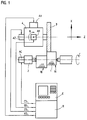
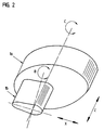
- FIG. 1 the concept of a numerically controlled is schematically Grinding machine for manufacturing the workpiece 1 shown in FIG. 2 shown.
- the workpiece 1 is NC-controlled by a spindle 2 Rotary axis C driven.
- the drive for this is with the reference symbol AC Mistake.
- the workpiece 1 is machined by a rotating one Grinding wheel 3.
- the grinding wheel 3 is along by means of a drive AZ the Z axis, by means of a drive AX along the X axis and by means of another drive AB can be moved numerically controlled about the B axis.
- the axes X and Z are perpendicular to each other, the C axis is one Axis of rotation about the Z axis and the B axis is an axis of rotation about a Axis perpendicular to the X and Z axes.
- the non-circular outer contour 1a of the Rotational axis C rotating workpiece 1 ground by the grinding slide 4 with the grinding wheel 3 an infeed movement in the X direction in Dependency of the angle of rotation C executes.
- This delivery movement is one Superposition of several partial movements resulting from the desired Target contour (shape of the outer contour 1a) of the workpiece 1 and the desired one Deduction depending on the blank or measurement results.
- these individual sub-processes are combined into groups, where only movements of the sub-processes within a group are dependent on each other during processing.
- the resulting target path for each axis X, Z, C, B (Control data) XD, ZD, CD, BD generated.
- the geometric and technological information entered on an input unit E of the numerical control defines the conditions for the individual sub-processes, such as travel distance and travel speed and form the NC program N, on the basis of which in a computing unit R of the control the manipulated variables XS, ZS, CS and BS are generated for each drive AX, AZ, AC, AB become.
- the entry can be made manually, by means of a data carrier or from an external computer or programming unit.
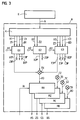
- the principle of the computing unit R is shown schematically in FIG. she consists of a coordination unit K, in which the data of the NC program N individual generators G1, G2, G3 for generating the control data X1P, Z1P, C1P, B1P, X2P, Z2P; X3P, Z3P, C3P, B3P for the axis movements be assigned.
- the data is divided in such a way that data of the sub-processes, the movements of which are interdependent can be fed to a single generator G1, G2 or G3.
- the generator G1 is responsible for the above Sub-processes number 1 to 4. This means that the generator G1 the required geometric and dynamic data (Acceleration, speed) of these sub-processes numbers 1 to 4 be fed to the NC program.
- This data which relates to the X axis refer to in Figure 3 with X1, which refer to the Z axis refer to Z1, which refer to the C axis with C1 and which refer to the B axis with B1. From this data are in an interpolator of the generator G1 for these subprocesses required control data X1P, Z1P, C1P and B1P for the controllers RX, RZ, RC and RB generated.
- the generator G2 is responsible for the sub-process number mentioned above 5, that is, for the infeed movement transverse to chip removal, in particular perpendicular to the target contour of the workpiece 1.
- the required geometric and dynamic data of the delivery process fed from the NC program N This data of this delivery process, which refer to the X axis are with X2 and the data which are refer to the Z axis are designated Z2. From this data in an interpolator of the generator G1 the necessary for this sub-process Control data X2P and Z2P generated for the controllers RX and RZ.
- the sub-processes contained in the generators G1 and G2 would become Grinding round contours is sufficient.
- a generator G3 is provided, which is used to generate the non-circular contour, is responsible for sub-process number 6. Should be a non-circular contour are processed, which is not conical in the Z direction, the generator G3 the data of the desired non-circular outer contour of the workpiece 1, ie the target contour 1a and the required dynamic data.
- the generator G3 generates X3 and C3 of the NC program from this data N control data X3P and C3P for controlling the drives AX and AC.
- the generator G3 contains an interpolator, which is independent of the generators G1 and G2 works and the data X3, C3 for the path control linked to each other along the target contour (outer contour 1a).
- the target contour is entered in a manner known per se on the input unit E of numerical control. It is particularly advantageous if the input interactively via a screen and a keyboard of the control he follows.
- the target contours of the workpiece 1 are in polar coordinates or in Cartesian coordinates in the dialog between the input unit E and operator described. The description is made either by Parameter input for mathematically determinable contours or through the Entry of value tables for mathematically not exactly defined forms. Once the geometric shapes have been entered, the NC blocks are generated.
- the assignment of the data of the NC program to the individual generators G1, G2, G3 can be done by coding the NC blocks so that the coordination unit K the division of the data depending on the Executes codes.
- the generators G1, G2, G3 in parallel are arranged to each other and work independently in parallel.
- control data X1P, Z1P, C1P, B1P and X2P, Z2P and X3P, Z3P, C3P is no synchronization between the generators G1, G2, G3 required.
- the NC program N predefined speed of the infeed movement changed and optimized become.
- the change relates to the resulting web speed, generated from the X and Z input data by interpolation. This measure allows the type of processing to be carried out in a simple manner such as roughing or finishing can be set and adjusted by the operator become.
- the infeed step length can also be influenced.
- the one specified by the NC program N can be used Rotational speed (web or peripheral speed) and thus the Cutting speed can be changed and optimized.
- the change relates refer to the resulting path, which is derived from the input data X3, C3 is generated by interpolation.
- Another advantage of the parallel arrangement of the generators G1, G2, G3 is that the interpolation clock of the individual generators G1, G2, G3 is independent can be adjusted from each other.
- the time grid in which the Support points of the path X3P, C3P are calculated using the generator G3, can for example be smaller than the time grid of the generator G1.
- the provision of the generator G3 has the particular advantage that the Control data X3P and C3P based on the specified geometric target contour of the workpiece 1 and predetermined dynamic data (Path speed) independent of the sub-processes of the generators G1, G2 can be generated.
- Programming and generation The control data X3P, C3P for the non-circular target contour 1a takes place independently of the position of the workpiece 1 and the grinding wheel 3.
- the dependence of the mutual position of the target contours 1a and 1b is achieved by prepositioning, i.e.
- the generator G1 determines the control data during the actual processing X3P and C3P of the generator G3 independently of the generator G1, i. H. also generated independently of input and output data of the generator G1 become.
- the description becomes by a partial process of the generator G1 the contour 1a and 1b (sub-process number 6 in generator G3) with the physical Position of the workpiece 1 and the grinding wheel 3 related.
- the control data X3P, C3P of the subprocesses for the contours 1a and 1b are independent of one another and independent of subprocesses of other generators G1, G2 in generator G3, that is to say exclusively from the data determining the contours 1a, 1b is generated.
- the control data X2P, Z2P for the infeed movement is generated independent of the generators G1 and G3 and independent of input data X1, Z1, C1, B1; X3, Z3, C3, B3 and output data X1P, Z1P, B1P, B1P X3P, Z3P, C3P, B3P of generators G1 and G3.
- the tax data X2P, Z2P in particular become independent of those that determine the target contour Data X3, Z3, C3, B3; X3P, Z3P, C3P, B3P (these are the Geometry and data determining the dynamics).
- control data X1P, Z1P, C1P, B1P; X2P, Z2P; X3P, C3P are used to generate the resulting control data XD, ZD, CD, BD superimposed on each other in add-on modules TX, TZ, TC, TD.
- This Control data XD, ZD, CD, BD become controllers in a manner known per se RX, RZ, RC, RB for generating the manipulated variables XS, ZS, CS, BS for the drives AX, AZ, AC, AB fed.
- the actual positions are shown in a known and therefore not shown in detail of workpiece 1 in relation to the C axis and the actual positions the grinding wheel 3 around the B axis and along the X and Z axes detected by position measuring systems and fed to the computing unit R.
- This feed is shown schematically in FIG. 3 for the X axis, the actual position of the grinding wheel 3 in the X direction is denoted by Xi.
- the generator G1 is number for the subprocesses 1 to 4 responsible. It is also possible to use sub-processes number 1 to 3 in one generator and sub-process number 4 in a separate generator to generate so that a total of four generators work in parallel.
- the non-circular contours can be any, it can also be sharp-edged Contours, such as polygonal contours with flat surfaces and sharp ones Edges that are ground from a cylindrical blank.
- the invention is not based on the described grinding of external contours limited, it can also be used when grinding inner contours as well as others Machining processes such as be used when milling.
- the rotating grinding wheel 3 by another tool, in particular replaced a rotating cutter.
Landscapes
- Engineering & Computer Science (AREA)
- Human Computer Interaction (AREA)
- Manufacturing & Machinery (AREA)
- Physics & Mathematics (AREA)
- General Physics & Mathematics (AREA)
- Automation & Control Theory (AREA)
- Numerical Control (AREA)
Abstract
Description
- Figur 1
- eine schematische Darstellung einer Schleifmaschine mit einer numerischen Steuerung,
- Figur 2
- ein Werkstück und
- Figur 3
- den Aufbau der numerischen Steuerung im Detail.
Claims (7)
- Numerische Steuerung zur Fertigung von unrunden Werkstücken (1) mita) einer Eingabeeinheit (E) zur Eingabe von ersten Daten (X1, Z1, C1, B1) zur Definition von Positionierbewegungen in mehreren Achsen (X, Z, C, B) zwischen Werkstück (1) und Werkzeug (3) die vor dem eigentlichen Bearbeitungsprozeß ablaufen sollen sowie von zweiten Daten (X2, Z2) zur Definition der Zustellbewegung des Werkzeuges (3) zur Spanabnahme und von dritten Daten (X3, Z3, C3, B3) zur Definition der unrunden Sollkontur (1a) des Werkstückes (1) in mehreren Achsen (X, Z, C, B);b) einer Koordinationseinheit (K) zum Zuführen der ersten Daten (X1, Z1, C1, B1) an einen ersten Generator (G1), Zuführen der zweiten Daten (X2, Z2) an einen zweiten Generator (G2) und Zuführen der dritten Daten (X3, Z3, C3, B3) an einen dritten Generator (G3);c) einen Addierbaustein (TX, TZ, TC, TB) für jede Achse (X, Z, C, B) zur Bildung von resultierenden Steuerdaten (XD, ZD, CD, BD) für einen Antrieb (AX, AZ, AC, AB) jeweils einer Achse (X, Z, C, B) durch Kombination der am Ausgang der Generatoren (G1, G2, G3) anstehenden Steuerdaten (X1P, Z1P, C1P, B1P; X2P, Z2P; X3P, Z3P, C3P, B3P) dieser Achsen (X, Z, C, B).
- Numerische Steuerung nach Anspruch 1, dadurch gekennzeichnet, daß jeder Generator (G1, G2, G3) eine Interpolationseinheit autweist.
- Numerische Steuerung nach Anspruch 1, dadurch gekennzeichnet, daß zumindest einem der Generatoren (G1, G2, G3) ein Mittel (A1, A2, A3) zugeordnet ist, um die Steuerdaten (X1P, Z1P, C1P, B1P; X2P, Z2P; X3P, Z3P, C3P, B3P) am Ausgang eines Generators (G1, G2, G3) ohne Beeinflussung der Steuerdaten (X1P, Z1P, C1P, B1P; X2P, Z2P; X3P, Z3P, C3P, B3P) eines anderen Generators (G1, G2, G3) beeinflussen zu können.
- Numerische Steuerung nach Anspruch 3, dadurch gekennzeichnet, daß dem zweiten Generator (G2) ein Mittel A2) zugeordnet ist, mit dem die Geschwindigkeit der Zustellbewegung (X2P, Z2P) oder die Schrittlänge der Zustellung beeinflußt wird.
- Numerische Steuerung nach Anspruch 3, dadurch gekennzeichnet, daß dem dritten Generator (G3) ein Mittel (A3) zugeordnet ist, mit dem die Bahngeschwindigkeit entlang der Sollkontur (1a) beeinflußt wird.
- Verfahren zum Betrieb einer numerischen Steuerung zur Fertigung von unrunden Werkstücken (1) mit den Verfahrensschritten:a) Eingabe von ersten Daten (X1, Z1, C1, B1) zur Definition von Positionierbewegungen zwischen Werkstück (1) und Werkzeug (3) in mehreren Achsen (X, Z, C, B) vor dem eigentlichen Bearbeitungsprozeß sowie von zweiten Daten (X2, Z2) zur Definition der Zustellbewegung des Werkzeuges (3) zur Spanabnahme und von dritten Daten (X3, Z3, C3, B3) zur Definition der unrunden Sollkontur (1a) des Werkstückes (1);b) Zuführen der ersten Daten (X1, Z1, C1, B1) an einen ersten Generator (G1), Zuführen der zweiten Daten (X2, Z2) an einen zweiten Generator (G2) und Zuführen der dritten Daten (X3, Z3, C3, B3) an einen dritten Generator (G3);c) unabhängige Berechnung von Steuerdaten (X1P, Z1P, C1P, B1P; X2P, Z2P; X3P, Z3P, C3P, B3P) in den Generatoren (G1, G2, G3) und Ausgabe dieser Steuerdaten (X1P, Z1P, C1P,B1P; X2P, Z2P; X3P, Z3P, C3P, B3P) für mehrere Achsen (X, Z, C, B);d) Bildung von resultierenden Steuerdaten (XD, ZD, CD, BD) für jeweils eine Achse (X, Z, C, B) durch Kombination der am Ausgang der Generatoren (G1, G2, G3) anstehenden Steuerdaten (X1P, Z1P, C1P, B1P; X2P, Z2P; X3P, Z3P, C3P, B3P) dieser Achsen (X, Z, C, B).
- Verfahren nach Anspruch 6, dadurch gekennzeichnet, daß in jedem der Generatoren (G1, G2, G3) ein Interpolationsverfahren unabhängig von den Interpolationsverfahren der anderen Generatoren (G1, G2, G3) abläuft.
Priority Applications (3)
| Application Number | Priority Date | Filing Date | Title |
|---|---|---|---|
| EP97115578A EP0902342B1 (de) | 1997-09-09 | 1997-09-09 | Numerische Steuerung zur Fertigung von unrunden Werkstücken |
| AT97115578T ATE228672T1 (de) | 1997-09-09 | 1997-09-09 | Numerische steuerung zur fertigung von unrunden werkstücken |
| DE59708830T DE59708830D1 (de) | 1997-09-09 | 1997-09-09 | Numerische Steuerung zur Fertigung von unrunden Werkstücken |
Applications Claiming Priority (1)
| Application Number | Priority Date | Filing Date | Title |
|---|---|---|---|
| EP97115578A EP0902342B1 (de) | 1997-09-09 | 1997-09-09 | Numerische Steuerung zur Fertigung von unrunden Werkstücken |
Publications (2)
| Publication Number | Publication Date |
|---|---|
| EP0902342A1 true EP0902342A1 (de) | 1999-03-17 |
| EP0902342B1 EP0902342B1 (de) | 2002-11-27 |
Family
ID=8227330
Family Applications (1)
| Application Number | Title | Priority Date | Filing Date |
|---|---|---|---|
| EP97115578A Expired - Lifetime EP0902342B1 (de) | 1997-09-09 | 1997-09-09 | Numerische Steuerung zur Fertigung von unrunden Werkstücken |
Country Status (3)
| Country | Link |
|---|---|
| EP (1) | EP0902342B1 (de) |
| AT (1) | ATE228672T1 (de) |
| DE (1) | DE59708830D1 (de) |
Cited By (3)
| Publication number | Priority date | Publication date | Assignee | Title |
|---|---|---|---|---|
| WO2000075737A1 (de) * | 1997-12-29 | 2000-12-14 | Hoermansdoerfer Gerd | Verfahren zum humpeldrehen und bevorzugte anwendungen des verfahrens |
| JP2008084129A (ja) * | 2006-09-28 | 2008-04-10 | Jtekt Corp | 数値制御装置のプログラムの記述方法、数値制御装置、及び加工装置 |
| EP1906280A3 (de) * | 2006-09-28 | 2011-02-23 | Jtekt Corporation | Programmschreibverfahren einer numerischen Steuerung, numerische Steuerung und damit gesteuerte Schneidmaschine |
Citations (6)
| Publication number | Priority date | Publication date | Assignee | Title |
|---|---|---|---|---|
| DE3722084A1 (de) * | 1986-07-04 | 1988-01-07 | Mitsubishi Electric Corp | Numerisch gesteuerte einrichtung |
| EP0103714B1 (de) * | 1982-09-07 | 1989-10-25 | General Electric Company | Mehrprozessoren-Achsensteuerung |
| EP0479026A1 (de) * | 1990-10-02 | 1992-04-08 | Ex-Cell-O GmbH | Maschine zum Unrundbearbeiten von Werkstücken |
| DE4032770A1 (de) * | 1990-10-16 | 1992-04-23 | Schaudt Maschinenbau Gmbh | Verfahren und vorrichtung zum schleifen unrunder werkstuecke |
| EP0304876B1 (de) * | 1987-08-25 | 1993-12-08 | Toyoda Koki Kabushiki Kaisha | Numerisch gesteuerte Werkzeugmaschine |
| EP0643343A1 (de) * | 1993-09-14 | 1995-03-15 | Siemens Aktiengesellschaft | Verfahren zur numerischen Bahnsteuerung von mehrachsigen Maschinen |
-
1997
- 1997-09-09 EP EP97115578A patent/EP0902342B1/de not_active Expired - Lifetime
- 1997-09-09 DE DE59708830T patent/DE59708830D1/de not_active Expired - Lifetime
- 1997-09-09 AT AT97115578T patent/ATE228672T1/de not_active IP Right Cessation
Patent Citations (6)
| Publication number | Priority date | Publication date | Assignee | Title |
|---|---|---|---|---|
| EP0103714B1 (de) * | 1982-09-07 | 1989-10-25 | General Electric Company | Mehrprozessoren-Achsensteuerung |
| DE3722084A1 (de) * | 1986-07-04 | 1988-01-07 | Mitsubishi Electric Corp | Numerisch gesteuerte einrichtung |
| EP0304876B1 (de) * | 1987-08-25 | 1993-12-08 | Toyoda Koki Kabushiki Kaisha | Numerisch gesteuerte Werkzeugmaschine |
| EP0479026A1 (de) * | 1990-10-02 | 1992-04-08 | Ex-Cell-O GmbH | Maschine zum Unrundbearbeiten von Werkstücken |
| DE4032770A1 (de) * | 1990-10-16 | 1992-04-23 | Schaudt Maschinenbau Gmbh | Verfahren und vorrichtung zum schleifen unrunder werkstuecke |
| EP0643343A1 (de) * | 1993-09-14 | 1995-03-15 | Siemens Aktiengesellschaft | Verfahren zur numerischen Bahnsteuerung von mehrachsigen Maschinen |
Non-Patent Citations (1)
| Title |
|---|
| POTTHAST A ET AL: "CNC-GESTEUERTES SCHLEIFEN VON FREIFORMKURVEN", 1 March 1991, ZWF ZEITSCHRIFT FUR WIRTSCHAFTLICHE FERTIGUNG UND AUTOMATISIERUNG, VOL. 86, NR. 3, PAGE(S) 112 - 116, XP000202695 * |
Cited By (6)
| Publication number | Priority date | Publication date | Assignee | Title |
|---|---|---|---|---|
| WO2000075737A1 (de) * | 1997-12-29 | 2000-12-14 | Hoermansdoerfer Gerd | Verfahren zum humpeldrehen und bevorzugte anwendungen des verfahrens |
| CZ297985B6 (cs) * | 1997-12-29 | 2007-05-16 | Zpusob nekruhového soustruzení na programovatelném soustruhu | |
| US7513913B2 (en) | 1997-12-29 | 2009-04-07 | Gerd Hoermansdoerfer | Hobble turning method and preferred applications for said method |
| US7942086B2 (en) | 1997-12-29 | 2011-05-17 | Hoermansdoerfer Gerd | Hobble turning method and preferred applications for said method |
| JP2008084129A (ja) * | 2006-09-28 | 2008-04-10 | Jtekt Corp | 数値制御装置のプログラムの記述方法、数値制御装置、及び加工装置 |
| EP1906280A3 (de) * | 2006-09-28 | 2011-02-23 | Jtekt Corporation | Programmschreibverfahren einer numerischen Steuerung, numerische Steuerung und damit gesteuerte Schneidmaschine |
Also Published As
| Publication number | Publication date |
|---|---|
| DE59708830D1 (de) | 2003-01-09 |
| EP0902342B1 (de) | 2002-11-27 |
| ATE228672T1 (de) | 2002-12-15 |
Similar Documents
| Publication | Publication Date | Title |
|---|---|---|
| EP2221693B1 (de) | Verfahren und Vorrichtung zum Erzeugen von Steuerdaten zum Steuern eines Werkzeugs an einer zumindest 5 Achsen umfassenden Werkzeugmaschine | |
| DE69232294T2 (de) | Numerische Steuerungseinheit | |
| DE602005001420T2 (de) | Verfahren zur Bearbeitung von Zahnrädern mit veränderlicher Geschwindigkeit | |
| EP1981674B1 (de) | Verfahren zum bearbeiten von kegelrädern im teilenden verfahren mit kompletter teilungsfehlerkompensation | |
| EP2823924B2 (de) | Doppelabrichter | |
| EP3552743A1 (de) | Vorrichtung und verfahren zur anfasbearbeitung eines verzahnten werkstücks | |
| DE3545795C2 (de) | Vorrichtung zur numerischen Steuerung | |
| DE102007045595A1 (de) | Verfahren und virtuelle Werkzeugmaschine zur Darstellung von Aktionen einer realen Werkzeugmaschine | |
| EP0631211B1 (de) | Verfahren für die Feinbearbeitung von Verzahnungen | |
| EP3945381A1 (de) | Herstellung durch kegelsegmente bestimmbarer flächen mittels einer werkzeugmaschine | |
| EP0212338B1 (de) | Verfahren zum spanabhebenden Bearbeiten der Oberfläche eines Nockens | |
| DE112014007112T5 (de) | Numerisch gesteuerte Vorrichtung | |
| DE3901621C2 (de) | Bearbeitungsvorrichtung | |
| DE3420938A1 (de) | Vorrichtung zum abrichten der regelscheibe fuer eine spitzenlose schleifmaschine | |
| DE69110583T2 (de) | Numerische steuerung. | |
| DE2755982A1 (de) | Werkzeugmaschine | |
| DE3910893A1 (de) | Numerische steuervorrichtung zur bearbeitung von unrunden werkstuecken | |
| EP0902342B1 (de) | Numerische Steuerung zur Fertigung von unrunden Werkstücken | |
| EP1312445B1 (de) | Verfahren, Vorrichtung und Software zum Profilschleifen und gleichzeitigen abrichten des Schleifwerkzeuges | |
| EP0563412B1 (de) | Werkzeugmaschine mit einer numerischen Steuerung zur Unterbrechung und Fortsetzung der Bearbeitung | |
| DE112021000558T5 (de) | Numerische Steuerung | |
| DE102018116553B4 (de) | Fräsverfahren | |
| DE2226547B2 (de) | Numerisch arbeitende Programmsteuerung für eine Werkzeugmaschine | |
| EP1556744A1 (de) | Neutraldaten-computersteuerungssystem für eine werkzeugmaschine zur herstellung von werkstücken mit schraubenmantelfläche sowie eine zugehörige werkzeugmaschine | |
| DE112018000229T5 (de) | Numerische Steuervorrichtung und Bearbeitungsverfahren |
Legal Events
| Date | Code | Title | Description |
|---|---|---|---|
| PUAI | Public reference made under article 153(3) epc to a published international application that has entered the european phase |
Free format text: ORIGINAL CODE: 0009012 |
|
| 17P | Request for examination filed |
Effective date: 19980501 |
|
| AK | Designated contracting states |
Kind code of ref document: A1 Designated state(s): AT CH DE FR GB IT LI |
|
| AX | Request for extension of the european patent |
Free format text: AL;LT;LV;RO;SI |
|
| AKX | Designation fees paid |
Free format text: AT CH DE FR GB IT LI |
|
| 17Q | First examination report despatched |
Effective date: 20000121 |
|
| GRAG | Despatch of communication of intention to grant |
Free format text: ORIGINAL CODE: EPIDOS AGRA |
|
| RAP1 | Party data changed (applicant data changed or rights of an application transferred) |
Owner name: DR. JOHANNES HEIDENHAIN GMBH |
|
| GRAG | Despatch of communication of intention to grant |
Free format text: ORIGINAL CODE: EPIDOS AGRA |
|
| GRAH | Despatch of communication of intention to grant a patent |
Free format text: ORIGINAL CODE: EPIDOS IGRA |
|
| GRAH | Despatch of communication of intention to grant a patent |
Free format text: ORIGINAL CODE: EPIDOS IGRA |
|
| GRAA | (expected) grant |
Free format text: ORIGINAL CODE: 0009210 |
|
| AK | Designated contracting states |
Kind code of ref document: B1 Designated state(s): AT CH DE FR GB IT LI |
|
| REF | Corresponds to: |
Ref document number: 228672 Country of ref document: AT Date of ref document: 20021215 Kind code of ref document: T |
|
| REG | Reference to a national code |
Ref country code: GB Ref legal event code: FG4D Free format text: NOT ENGLISH |
|
| REG | Reference to a national code |
Ref country code: CH Ref legal event code: EP |
|
| REG | Reference to a national code |
Ref country code: CH Ref legal event code: NV Representative=s name: TROESCH SCHEIDEGGER WERNER AG |
|
| REF | Corresponds to: |
Ref document number: 59708830 Country of ref document: DE Date of ref document: 20030109 |
|
| GBT | Gb: translation of ep patent filed (gb section 77(6)(a)/1977) |
Effective date: 20030214 |
|
| ET | Fr: translation filed | ||
| PLBE | No opposition filed within time limit |
Free format text: ORIGINAL CODE: 0009261 |
|
| STAA | Information on the status of an ep patent application or granted ep patent |
Free format text: STATUS: NO OPPOSITION FILED WITHIN TIME LIMIT |
|
| 26N | No opposition filed |
Effective date: 20030828 |
|
| PGFP | Annual fee paid to national office [announced via postgrant information from national office to epo] |
Ref country code: AT Payment date: 20080915 Year of fee payment: 12 |
|
| PGFP | Annual fee paid to national office [announced via postgrant information from national office to epo] |
Ref country code: GB Payment date: 20090922 Year of fee payment: 13 Ref country code: CH Payment date: 20090923 Year of fee payment: 13 |
|
| PGFP | Annual fee paid to national office [announced via postgrant information from national office to epo] |
Ref country code: IT Payment date: 20090926 Year of fee payment: 13 |
|
| PG25 | Lapsed in a contracting state [announced via postgrant information from national office to epo] |
Ref country code: AT Free format text: LAPSE BECAUSE OF NON-PAYMENT OF DUE FEES Effective date: 20090909 |
|
| REG | Reference to a national code |
Ref country code: CH Ref legal event code: PL |
|
| GBPC | Gb: european patent ceased through non-payment of renewal fee |
Effective date: 20100909 |
|
| PG25 | Lapsed in a contracting state [announced via postgrant information from national office to epo] |
Ref country code: IT Free format text: LAPSE BECAUSE OF NON-PAYMENT OF DUE FEES Effective date: 20100909 |
|
| REG | Reference to a national code |
Ref country code: FR Ref legal event code: ST Effective date: 20110531 |
|
| PG25 | Lapsed in a contracting state [announced via postgrant information from national office to epo] |
Ref country code: LI Free format text: LAPSE BECAUSE OF NON-PAYMENT OF DUE FEES Effective date: 20100930 Ref country code: CH Free format text: LAPSE BECAUSE OF NON-PAYMENT OF DUE FEES Effective date: 20100930 Ref country code: FR Free format text: LAPSE BECAUSE OF NON-PAYMENT OF DUE FEES Effective date: 20100930 |
|
| PG25 | Lapsed in a contracting state [announced via postgrant information from national office to epo] |
Ref country code: GB Free format text: LAPSE BECAUSE OF NON-PAYMENT OF DUE FEES Effective date: 20100909 |
|
| PGFP | Annual fee paid to national office [announced via postgrant information from national office to epo] |
Ref country code: FR Payment date: 20091001 Year of fee payment: 13 |
|
| PGFP | Annual fee paid to national office [announced via postgrant information from national office to epo] |
Ref country code: DE Payment date: 20140922 Year of fee payment: 18 |
|
| REG | Reference to a national code |
Ref country code: DE Ref legal event code: R119 Ref document number: 59708830 Country of ref document: DE |
|
| PG25 | Lapsed in a contracting state [announced via postgrant information from national office to epo] |
Ref country code: DE Free format text: LAPSE BECAUSE OF NON-PAYMENT OF DUE FEES Effective date: 20160401 |