EP0902337B1 - Image forming device equipped with a releasable fixing device - Google Patents
Image forming device equipped with a releasable fixing device Download PDFInfo
- Publication number
- EP0902337B1 EP0902337B1 EP98305882A EP98305882A EP0902337B1 EP 0902337 B1 EP0902337 B1 EP 0902337B1 EP 98305882 A EP98305882 A EP 98305882A EP 98305882 A EP98305882 A EP 98305882A EP 0902337 B1 EP0902337 B1 EP 0902337B1
- Authority
- EP
- European Patent Office
- Prior art keywords
- fixing
- fixing device
- image
- roll
- paper
- Prior art date
- Legal status (The legal status is an assumption and is not a legal conclusion. Google has not performed a legal analysis and makes no representation as to the accuracy of the status listed.)
- Expired - Lifetime
Links
Images

Classifications
-
- G—PHYSICS
- G03—PHOTOGRAPHY; CINEMATOGRAPHY; ANALOGOUS TECHNIQUES USING WAVES OTHER THAN OPTICAL WAVES; ELECTROGRAPHY; HOLOGRAPHY
- G03G—ELECTROGRAPHY; ELECTROPHOTOGRAPHY; MAGNETOGRAPHY
- G03G21/00—Arrangements not provided for by groups G03G13/00 - G03G19/00, e.g. cleaning, elimination of residual charge
- G03G21/16—Mechanical means for facilitating the maintenance of the apparatus, e.g. modular arrangements
- G03G21/1604—Arrangement or disposition of the entire apparatus
- G03G21/1623—Means to access the interior of the apparatus
- G03G21/1638—Means to access the interior of the apparatus directed to paper handling or jam treatment
-
- G—PHYSICS
- G03—PHOTOGRAPHY; CINEMATOGRAPHY; ANALOGOUS TECHNIQUES USING WAVES OTHER THAN OPTICAL WAVES; ELECTROGRAPHY; HOLOGRAPHY
- G03G—ELECTROGRAPHY; ELECTROPHOTOGRAPHY; MAGNETOGRAPHY
- G03G15/00—Apparatus for electrographic processes using a charge pattern
- G03G15/20—Apparatus for electrographic processes using a charge pattern for fixing, e.g. by using heat
- G03G15/2003—Apparatus for electrographic processes using a charge pattern for fixing, e.g. by using heat using heat
- G03G15/2014—Apparatus for electrographic processes using a charge pattern for fixing, e.g. by using heat using heat using contact heat
- G03G15/2017—Structural details of the fixing unit in general, e.g. cooling means, heat shielding means
- G03G15/2032—Retractable heating or pressure unit
- G03G15/2035—Retractable heating or pressure unit for maintenance purposes, e.g. for removing a jammed sheet
-
- G—PHYSICS
- G03—PHOTOGRAPHY; CINEMATOGRAPHY; ANALOGOUS TECHNIQUES USING WAVES OTHER THAN OPTICAL WAVES; ELECTROGRAPHY; HOLOGRAPHY
- G03G—ELECTROGRAPHY; ELECTROPHOTOGRAPHY; MAGNETOGRAPHY
- G03G2221/00—Processes not provided for by group G03G2215/00, e.g. cleaning or residual charge elimination
- G03G2221/16—Mechanical means for facilitating the maintenance of the apparatus, e.g. modular arrangements and complete machine concepts
- G03G2221/1639—Mechanical means for facilitating the maintenance of the apparatus, e.g. modular arrangements and complete machine concepts for the fixing unit
-
- G—PHYSICS
- G03—PHOTOGRAPHY; CINEMATOGRAPHY; ANALOGOUS TECHNIQUES USING WAVES OTHER THAN OPTICAL WAVES; ELECTROGRAPHY; HOLOGRAPHY
- G03G—ELECTROGRAPHY; ELECTROPHOTOGRAPHY; MAGNETOGRAPHY
- G03G2221/00—Processes not provided for by group G03G2215/00, e.g. cleaning or residual charge elimination
- G03G2221/16—Mechanical means for facilitating the maintenance of the apparatus, e.g. modular arrangements and complete machine concepts
- G03G2221/1678—Frame structures
- G03G2221/1687—Frame structures using opening shell type machines, e.g. pivoting assemblies
Definitions
- the present invention relates to an image forming device comprising a fixing device for heat-fixing a formed unfixed image of a toner image and the like, in a copying machine, laser beam printer and the like using an electrophotograph method.
- the image forming device utilizing an electrophotograph method creates a manifest image by powder toner from a latent image formed on a photosensitive body having a photosensitive layer which works as a recording medium, and transfers said manifested toner image onto a sheet-type paper which is the image holding body, and since said toner is unfixed, heat is applied to melt the toner, and then pressure is added thereto to fix said toner image onto the paper.
- a fixing device is provided on the down stream side of a paper conveyance passage which passes through an image forming region, for example, just before a discharge portion of the paper.
- a fixing device is formed of a heat roll having in the interior thereof a heater lamp comprising a halogen lamp as the heating source, and a pressurization roll pressurized to said heat roll by a predetermined pressurization force.
- the fixing device is positioned in front of a discharge portion opening to the exterior of the conveyance passage which passes through an image forming portion, wherein a toner image on a sheet-type paper formed at the image forming portion is contacted to the heat roll, and by the heat of the heat roll and the pressurization force provided in co-operation with the pressurization roll, the toner image is heat-fixed to the sheet.
- the heat roll comprised in the fixing device is equipped with the heater lamp positioned inside a cylinder having a pipe of aluminum (Al) as a cored bar, the cylinder surface being covered by a silicon rubber member and the like having a good releasing character against the toner and the like.
- the silicon rubber covering layer and the cored bar are adhered and fixed together by an adhesive called a primer, thereby forming the heater roll.
- the surface of the heat roll is maintained at a fixable temperature, in order to heat-fix said toner to the sheet of paper. Therefore, a heat detection sensor such as a thermistor is mounted so as to contact the surface of the heat roll, and in response to the heat detection signal from the sensor, the driving control of the power supply for the heater lamp is operated, and the heat roll surface temperature is maintained at a set temperature enabling fixing operation.
- a heat detection sensor such as a thermistor is mounted so as to contact the surface of the heat roll, and in response to the heat detection signal from the sensor, the driving control of the power supply for the heater lamp is operated, and the heat roll surface temperature is maintained at a set temperature enabling fixing operation.
- pressurization roll is forced toward the heat roll by a pressurization lever so as to press the paper in the heat roll direction.
- the pressurization lever is axially supported on one end, and the other end is forced by a spring so as to pressurize the roll toward the heat roll.
- a cleaning means is provided.
- the cleaning means either presses a cleaning pad, or a cleaning web, onto the roll surface, so as to wipe off the adhered toner on the heat roll.
- an application device for applying to the heat roll surface an oil having good releasing ability against toner, such as silicon oil.
- the application device comprises an application roll for applying oil to the heat roll surface, an oil tank for storing the oil of an offset preventing liquid, a supply felt for supplying the oil in the oil tank to the application roll surface, and a blade for uniforming the oil supplied to the application roll.
- the felt for supplying oil is submerged at one end to the oil inside the oil tank, and the other end of the felt is pressurized by a forcing means of spring and the like so as to contact the application roll.
- the oil supplied to the rotating application roll is flattened uniformly by the blade , and by rotating with contact to the heat roll, a uniform oil layer could be applied to the heat roll surface.
- the fixing device having the above mentioned structure is formed as a unit and mounted removably to the image forming device body. Therefore, each of the above-mentioned members are stored inside a casing so as to form one unit. On the casing is formed an opening for introducing the paper to the pressurizing portion between the heat roll and the pressurization roll, and a discharge exit for discharging the fixed paper.
- a guide for guiding the paper to rollers, and a positioning hole for positioning the unit of the fixing device to the predetermined position in the image forming device body are formed to the casing.
- the casing forming the fixing device unit is further equipped with a fixed piece for fixing the fixing device to the mounting stage, and a fixing piece formed on the mounting stage. The two pieces are fixed by a fixing screw.
- the fixing device formed as one unit when the paper is jammed at that position, a part of the image forming device is opened, and the fixing state between the mounting stage is released, or in other words, the fixing screw is removed, and the fixing device is taken out by the whole unit. Thereafter, the pressurized state of the heat roll and the pressurization roll is released.
- the release structure works so as to remove the pressure by rotating the pressurization lever against the force of the spring. Thereby, the jammed paper could be removed easily.
- the fixing device formed as a unit it is mounted removably to the image forming device body so as to simplify the jam management and the like, thereby considering easy maintenance for the user. Moreover, the fixing device has a shorter life than the fixing device body, and the general removable structure enables easy replacement. In other words, in order to improve the serviceability and the operability(operational characters), the fixing device is mounted removably to the image forming device body.
- the conventional fixing device was considered to pull out the jammed paper in the paper conveyance direction in order to solve the fouling caused by the unfixed toner, thereby improving the serviceability and the operability of the jam management.
- the unfixed toner image is fixed to the paper by the remaining heat of the heat roll in the fixing device.
- the fixing device the providing of electricity to the heater lamp in the heat roll is also released when the jam has occurred, so therefore, the fixing of the unfixed toner may not always be performed completely merely by the use of remaining heat of the heat roll.
- the fixing performance may be very unfavorable, and the paper may be pulled out in a unfixed state, causing fouling by the toner.
- the pressure of the pressurization roll is released. Then sufficient pressurization status will not be maintained, and fixing disorder of the unfixed toner image may occur, leading to the above mentioned problems.
- the unfixed toner may be dispersed when pulling out the paper, spoiling not only the fixing device but also or even other components the user. In this case, when the toner contaminates the application felt preventing offset, it may cause an uneven application of oil, and stable fixing could no longer be performed.
- the unfixed toner will not foul the interior of the image forming device.
- the fixing screw working as the fixing means must be removed, and further, the pressure on the pressurization roll must be released. The operation may become complex, and when the user forgets to release the pressure, the removal of the jammed paper may be difficult, or unfixed toner may be dispersed by the removing operation, fouling the user.
- US-A-4 806 970 discloses an image recording device having a removable fixing device including a pressure roller and a heater roller. When a handle 154 for removing the fixing device is moved into an upright position, pressure between the pressure roller and heater roller is released.
- the invention provides an image recording apparatus as set out in claim 1.
- the invention also provides a fixing device as set out in claim 6.
- the fixing device when removing the fixing device from the image forming device, the fixed state of the fixing device is released with linkage to the operation to release the pressurized state. Therefore, the fixture of the fixing device could be released by one operation, and it could be taken out easily from the image forming device. Therefore, the jammed paper could be removed from the fixing device easily, increasing the serviceability and the operability greatly.
- the pressurization release is equipped with a rotating release lever (53), the release lever (53) equipped with a member such as a cam (53a) for rotating a pressurization lever (50) pressurizing the pressurization roll (42) to the heat roll (41) side in opposition to the force of a spring (52) forcing the pressurization lever to the heat roll (41) side, further equipped with a connecting member (53b, 54b) for rotating a fixing lever (54) forced continuously toward the fixing direction so as to fix the fixing device to a mounting stage (fixed position 57) to the fix release direction.
- a rotating release lever 53
- the release lever (53) equipped with a member such as a cam (53a) for rotating a pressurization lever (50) pressurizing the pressurization roll (42) to the heat roll (41) side in opposition to the force of a spring (52) forcing the pressurization lever to the heat roll (41) side
- a fixing piece (54c) of the fixing lever (54) is dislocated from a fixing slit (57b) on the mounting stage, and the fixed state is simultaneously released. Therefore, simultaneously as the pressurization release of the pressurization roll against the heat roll, the fixed state of the fixing device could be released by only one operation.
- the structure realizing such effect could be performed by a simple structure merely adding a fixing lever, thereby simplifying the removal operation of jammed paper.
- the image forming device may comprise a limiting means for disabling the pulling out of said image holding body to the same direction as the conveyance direction of said image holding body, but rather, enabling the pulling out of said image holding body to the opposite direction after said fixing device is removed.
- the jammed paper could be removed.
- the jammed paper could not be removed by pulling out to the paper conveyance direction, but rather, could be removed easily by pulling it out in the opposite direction. Therefore, the unfixed toner would not contact the heat roll, but instead, only the toner which has already been fixed will contact the heat roll, which leads to easy removal of paper by causing no. spread of toner due to fixing disorder.
- the limiting means for disabling the pulling out of the image holding body to the conveyance direction and enabling the pulling out in the opposite direction could be formed by a one-way clutch which enables transmission of drive force to the heat roll or the pressurization roll in the conveyance direction of the image holding body, and freeing the drive to the other direction.
- the image holding body in the fixture released state of the fixing device, when removing the fixing device, the image holding body could be held between the two rolls, and released of its pressure at a state where the image holding body could be removed simultaneously. Then, there will be no fear of the jammed paper being dropped inside the image forming device, and there is no chance of the image forming device interior being fouled by the dispersed toner.
- FIG. 1 is a drawing showing the structure of the prior art fixing device.
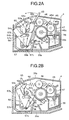
- FIG. 2A is a drawing showing the first embodiment for performing the pressurization release and fixture release of the fixing device according to the present invention, and shows the state where the fixing device is fixed to the image forming device.
- FIG. 2B is a drawing showing the first embodiment for performing the pressurization release and fixture release of the fixing device according to the present invention, and shows the state where the fixed state of the fixing device against the image forming device is released.
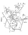
- FIG. 3 is a schematic view showing one example of the structure for releasing the pressure and fixture of the fixing device shown in FIGS. 2A and 2B.
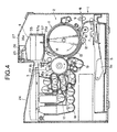
- FIG. 4 is a drawing showing the whole structure of the image forming device comprising the fixing device of FIGS. 2A and 2B.
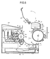
- FIG. 5 is a drawing showing one example of the structure for taking out the fixing device from the image forming device of FIG. 5.
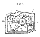
- FIG. 6 is a drawing showing the pressure released state of the fixing device for explaining the third embodiment of the present invention.
- a fixing device 60 is formed of a heat roll 62 having in the interior thereof a heater lamp 61 comprising a halogen lamp as the heating source, and a pressurization roll 63 pressurized to said heat roll 62 by a predetermined pressurization force.
- the fixing device 60 shown in FIG. 1 is positioned in front of a discharge portion opening to the exterior of the conveyance passage which passes through an image forming portion, wherein a toner image 64 on a sheet-type paper P formed at the image forming portion is contacted to the heat roll 62, and by the heat of the heat roll 62 and the pressurization force provided in co-operation with the pressurization roll 63, the toner image is heat-fixed to the sheet.
- the heat roll 62 comprised in the fixing device 60 is equipped with the heater lamp 61 positioned inside a cylinder having a pipe of aluminum (Al) as a cored bar, the cylinder surface being covered by a silicon rubber member and the like having a good releasing character against the toner and the like.
- the silicon rubber covering layer and the cored bar are adhered and fixed together by an adhesive called a primer, thereby forming the heater roll 62.
- the surface of the heat roll 62 is maintained at a fixable temperature, in order to heat-fix said toner to the sheet of paper P. Therefore, a heat detection sensor 65 such as a thermistor is mounted so as to contact the surface of the heat roll 62, and in response to the heat detection signal from the sensor 65, the driving control of the power supply for the heater lamp 61 is operated, and the heat roll 62 surface temperature is maintained at a set temperature enabling fixing operation.
- a heat detection sensor 65 such as a thermistor
- pressurization roll 63 is forced toward the heat roll 62 by a pressurization lever 66 so as to press the paper P to the heat roll 62 direction.
- the pressurization lever 66 is axially supported on one end, and the other end is forced by a spring 67 so as to pressurize the roll 63 toward the heat roll 62.
- a cleaning means 68 is provided.
- the cleaning means 68 either presses a cleaning pad, or a cleaning web as shown in the drawing, onto the roll surface, so as to wipe off the adhered toner on the heat roll 62.
- an application device 69 for applying to the heat roll 62 surface an oil having good releasing ability against toner, such as silicon oil is further equipped.
- the application device 69 comprises an application roll 69a for applying oil to the heat roll 62 surface, an oil tank 69b for storing the oil of an offset preventing liquid, a supply felt 69c for supplying the oil in the oil tank 69b to the application roll 69a surface, and a blade 69d for uniforming the oil supplied to the application roll 69a.
- the felt 69c for supplying oil is submerged at one end to the oil inside the oil tank 69b, and the other end of the felt 69c is pressurized by a forcing means of spring and the like so as to contact the application roll 69a.
- the oil supplied to the rotating application roll 69a is flattened uniformly by the blade 69d, and by rotating with contact to the heat roll 62, a uniform oil layer could be applied to the heat roll 62 surface.
- the fixing device 60 having the above mentioned structure is formed as a unit and mounted removably to the image forming device body. Therefore, each of the above-mentioned members are stored inside a casing 70 so as to form one unit. On the casing 70 is formed an opening 71 for introducing the paper P to the pressurizing portion between the heat roll 62 and the pressurization roll 63, and a discharge exit 72 for discharging the fixed paper P.
- a guide 73 .for guiding the paper P to rollers 62 and 63, and a positioning hole 74 for positioning the unit of the fixing device 60 to the predetermined position in the image forming device body are formed to the casing.
- the casing 70 forming the fixing device 60 unit is further equipped with a fixed piece 77 for fixing the fixing device 60 to the mounting stage 75, and a fixing piece 78 formed on the mounting stage 65. The two pieces are fixed by a fixing screw 79.
- the fixing device 70 formed as one unit, when the paper P is jammed at that position, a part of the image forming device is opened, and the fixing state between the mounting stage 75 is released, or in other words, the fixing screw 79 is removed, and the fixing device 60 is taken out by the whole unit. Thereafter, the pressurized state of the heat roll 62 and the pressurization roll 63 is released.
- the release structure works so as to remove the pressure by rotating the pressurization lever 66 against the force of the spring 67. Thereby, the jammed paper P could be removed easily.
- the fixing device 60 formed as a unit, it is mounted removably to the image forming device body so as to simplify the jam management and the like, thereby considering easy maintenance for the user. Moreover, the fixing device 60 has a shorter life than the fixing device body, and the general removable structure enables easy replacement. In other words, in order to improve the serviceability and the operability(operational characters), the fixing device 60 is mounted removably to the image forming device body.
- the conventional fixing device was considered to pull out the jammed paper to the paper conveyance direction in order to solve the fouling caused by the unfixed toner, thereby improving the serviceability and the operability of the jam management.
- the unfixed toner image is fixed to the paper by the remaining heat of the heat roll 62 in the fixing device.
- the fixing device 60 the providing of electricity to the heater lamp 61 in the heat roll 62 is also released when the jam has occurred, so therefore, the fixing of the unfixed toner may not always be performed completely merely by the use of remaining heat of the heat roll 62.
- the fixing performance may be very unfavorable, and the paper may be pulled out in a unfixed state, causing fouling by the toner.
- the unfixed toner may be dispersed when pulling out the paper, fouling not only the fixing device 60 but also the user or other components. In this case, when the toner contaminates the application felt 69c preventing offset, it may cause an uneven application of oil, and stable fixing could no longer be performed.
- a web method-type cleaning means 68 is effective.
- this method causes complication of the structure, increasing the size of the fixing device 70 and the cost.
- Further disadvantage of the method is the occurrence of oil lines on an OHP sheet.
- the unfixed toner will not foul the interior of the image forming device.
- the fixing screw 79 working as the fixing means must be removed, and further, the pressure on the pressurization roll 63 must be released. The operation may become complex, and when the user forgets to release the pressure, the removal of the jammed paper P may be difficult, or unfixed toner may be dispersed by the removing operation, fouling the user.
- FIGS. 2A and 2B is a partial cross-sectional side view showing the fixed state and the fixture released state of the fixing device to the image forming device body for explaining the first embodiment of the present invention, wherein FIG. 2A shows the fixed state, and FIG. 2B shows the fixture released state.
- FIG. 3 is a schematic view showing the detailed structure for fixing or releasing the fixing device shown in FIGS. 2A and 2B
- FIG. 4 is a view showing the whole structure of the image forming device comprising the fixing device of FIGS. 2A and 2B.
- the image forming device shown in FIG. 4 is composed of a paper feed portion 1 for storing and supplying the sheet of paper which works as a recording paper where the toner image will finally be formed, a transfer portion 2 for transferring a toner image to the sheet of paper, an image forming portion 3 comprising a developing device and the like for forming the toner image, and a fixing device 4 according to the present invention for melting and fixing the toner image transferred to the sheet.
- a paper feed cassette 5 for storing the sheets of paper and positioned removably on the lowest area of the image forming device body, especially enabled to be pulled out from the front side or the right side (the front side of the device) in the drawing, and a manual feed inserting portion 6 for inserting the sheets of paper manually positioned on the front side of the device body, or the right side of the drawing.
- a pickup roll 7 for sending out one paper at a time from the top portion of the sheets of paper being stored inside the paper feed cassette 5
- a PF roll 8 for conveying the sheet paper sent out by said pickup roll
- a manual feed roll 9 for conveying the sheet of paper inserted from the manual feed inserting portion 6.
- a pre-curl roll 10 for curling in advance the paper being conveyed from said PF roll 8 and said manual feed roll 9 is mounted thereto. These units form said paper feed portion 1.
- the paper is sent out from said paper feed portion 1 to the transfer portion 2 according to image forming orders.
- said paper feed cassette 5 On said paper feed cassette 5 is mounted a push-up member or sheet mounting table 5a forced toward the upper direction in the drawing by a spring and the like, and on this sheet mounting table 5a is mounted the sheets of paper.
- the paper stored inside said paper feed cassette 5 is positioned so that the top paper thereof is opposed to the pickup roll 7, and by one driving rotation of the pickup roll 7 toward the direction of the arrow, the roll contacts the top sheet, and one paper will be sent out.
- the sent out paper is conveyed to the pre-curl roll 10 by way of the PF roll 8.
- the sheet of paper being inserted from the manual feed inserting portion 6 will be conveyed to the pre-curl roll 10 through the manual feed roll 9.
- Said pre-curl roll 10 curls the paper in advance being conveyed as explained above, which makes the paper to be easily adsorbed and held at the surface of a cylindrical transfer drum 11 equipped at the transfer portion 2.
- the cylindrical transfer drum 11 mentioned above is equipped to said transfer portion 2 as transfer means.
- members such as a ground roll 12 as a grounded electrode member, a guide member 13 for guiding the sheet so as not to fall from said transfer drum 11, a removing pawl 14 for removing the sheet adsorbed to said transfer drum 11, and the like are positioned.
- Said removing pawl 14 is mounted movably so as to either contact to or separate from the surface of said transfer drum 11, which removes the sheet from the transfer drum 11 after the transfer has finished.
- a photosensitive drum 15 pressing against said transfer drum 11 is mounted as the image holding body.
- This photosensitive drum 15 is formed of a conductive aluminum pipe 15a being grounded, and an OPC film (organic optical conductive film) 15b, for example, is applied to the surface thereof.
- developers 16, 17, 18 and 19 each storing a toner of yellow, magenta, cyan, and black are positioned radially in order, and moreover, an electrifier 20 for electrifying the surface of said photosensitive drum 15, a cleaning blade 21 for sweeping off and removing the remainder toner on the surface of the photosensitive drum 15, and so on are positioned.
- an electrifier 20 for electrifying the surface of said photosensitive drum 15
- a cleaning blade 21 for sweeping off and removing the remainder toner on the surface of the photosensitive drum 15, and so on are positioned.
- a toner image is formed on said photosensitive drum 15 for each of said toners, and the image will be transferred one after the other on the sheet of paper wound around said transfer drum 11. Therefore, according to the photosensitive drum 15, electrification, exposure, development, and transfer is repeatedly performed for each color, thereby forming an image having the desired color on the paper.
- a toner image is transferred to the sheet paper adsorbed electrostaticly to the transfer drum 11, one color at a time for each one rotation of the transfer drum 11, thereby gaining a colored image with each color on top of the other, by a maximum of four rotations.
- the photosensitive drum 15 and the transfer drum 11 are pressed to each other so that a pressure of approximately 8kg is added to the transfer position, especially in the contacting portion, from the point of view of transfer efficiency and image quality.
- the toner image formed on the sheet paper by the above-mentioned method is unfixed, and in order to finish the image as a permanent image, a fixing device 4 for performing heat-fixing according to the present invention is positioned corresponding to the mounting position of the removing pawl 14 of the transfer drum 11.
- This fixing device 4 which will be explained in detail hereinafter comprises a heat roll 41 for fixing the toner image formed on the sheet of paper by a predetermined temperature and pressure, and a fixing guide for guiding the sheet removed from the transfer drum 11 by the removing pawl 14 to the heat roll 41.
- a discharge roll 23 is mounted, and the sheet after the fixture is discharged to a discharge tray 24 mounted on the exterior of the image forming device body.
- the discharge tray 24 is positioned on the upper portion of the image forming device, and mounted in a slant state.
- a discharge passage 25 is further equipped between the discharge exit on the side of the fixing device 4 to the discharge roll 23, in order to guide the sheet of paper being discharged from the fixing device 4 to the discharge roll 23.
- a detection sensor 26 for detecting the sheet of paper being sent out from the fixing device 4. Simultaneously as detecting the discharge of said sheet of paper, the jam detection in the fixing device is performed.
- the jam detection is performed in correspondence to the time the bottom end of the paper passes, according to each of the paper size.
- the fixing device 4 includes a heat roll 41 comprising on the surface of a cored bar 31 having a cylindrical shape formed of aluminum Al a rubber covering layer 32 having an advantageous release ability against toner, such as silicon rubber, bonded and fixed thereto by an adhesive called a primer or the like.
- a heater lamp 43 formed of a heating source such as a halogen lamp for maintaining the surface temperature of the heat roll to a fixable temperature (set temperature).
- a pressurization roll 42 is mounted, which is formed by covering a cored bar 33 supported rotatably with a silicon rubber or a sponge which is either or both thick and/or with low hardness covered by a PFA tube 34.
- This pressurization roll 42 improves the adiabatic performance by mounting said thick cover layer 34, and is also considered to reduce the temperature reduction of the heat roll 41 surface on the image side, and forming a large nip width in the conveyance direction contacting said heat roll 41.
- power supply to the heater lamp 43 is controlled so as to maintain the surface temperature of said heat roll 41 to a predetermined set temperature.
- a heat detection sensor 44 formed of a thermistor and the like is mounted to a position contacting the surface of the heat roll 41.
- the control of power supply to the heater lamp 43 is performed.
- a cleaning roll 46 is mounted rotatably so as to contact the heat roll 41 surface in order to remove the toner adhered to the roll 41 surface.
- the application device 45 comprises an application roll 45a, an oil tank 45b for storing oil, a supply felt 45c for supplying oil, and a blade 45d for making even the oil on the surface of the application roll 45a.
- the one end of the supply felt 45c is submerged to the oil in the oil tank 45b, drawing up the oil by the capillary phenomenon, and supplies oil by the other end pressed against the application roll 45a.
- the tip region of the supply felt 45c is pressed against the application roll 45a by a spring 48 and a pressing member 47.
- the excessive oil supplied by the supply felt 45c is returned to the oil tank 45b by a recovery felt 49.
- the oil is supplied and applied by the supply felt 45c to the application roll 45a, and the excessive oil supplied to the application roll 45a is wiped off by the blade 45d.
- a uniform oil layer will be formed to the application roll 45a surface, and by the rotation of the application roll 45a, oil will be applied to the heat roll 41.
- oil preventing offset is applied in a uniform state to the heat roll 41.
- the adhesion of toner to the heat roll 41 is restrained by the application of oil. However, the toner adhesion could not be prevented completely. Therefore, the cleaning roll 46 for cleaning the adhered toner is rotatably mounted.
- the cleaning roll 46 is formed of a non-woven fabric and the like. In order to improve the cleaning performance, it is driven so as to rotate in the opposite direction as the rotating direction of the heat roll 41, especially in the contacting area. Further, when it is formed to rotate in the same direction, the peripheral velocity of the cleaning roll 46 should be set to differ from the peripheral velocity of the heat roll 41.
- the paper is separated from the transfer drum 11 and guided to the fixing device 4 as shown in FIGS. 2A and 2B by way of a guide not shown.
- the toner is melted by the heat of the heat roll 41, and the toner is fixed to the paper by the compression force.
- the paper being completed of the fixing process is discharged onto the discharge tray 24 by way of the discharge passage 25 by the discharging operation of the discharge roll 23.
- the heat roll 41, the pressurization roll 42, the oil application device 45, the cleaning roll 46 and the like are stored and mounted inside a casing 35.
- a concave portion as shown in FIG. 4, specifically, a handle 35c for lifting up the fixing device 4.
- the two rolls 41 and 42 are supported rotatably by a frame 36 formed on both sides of the casing through bearings 37, 38.
- the frame 36 forms one portion of the casing 35.
- the bearing 37 formed on the frame 36 is fixed in position.
- the bearing 38 for rotatably supporting the pressurization roll 42 is movably mounted to a long hole formed on the frame 37 so as to enable movement in the heat roll 41 direction.
- the pressurization roll 42 is formed to be pressurized toward the heat roll 41 by a predetermined pressure. Therefore, a pressurization lever 50 for forcing the bearing 38 rotatably supporting the pressurization roll 42 is mounted so as to contact thereto.
- the pressurization lever 50 is mounted at one end to the frame 36 by a step screw 51, supported so as to rotate with the step screw 51 positioned at the center of rotation.
- On the other end of the pressurization lever 50 from the supporting portion is mounted one end of a spring 52. Since the other end of the spring 52 is mounted to a mounting portion 36a on the frame 36, the pressurization roll 42 is pressurized toward the heat roll 41 side by the force of the spring 52.
- a release lever 53 is mounted rotatably to the frame 36.
- On the release lever 53 is formed integrally a cam 53a for releasing the pressurized state by the pressurization lever 50, and a connecting pin 53b linked to a fixing lever 54 for fixing the unit of the fixing device 4 to the predetermined position on the image forming device.
- the cam 53a is formed so as to place an axis 53c enabling rotation of the release lever 53 against the frame 36 at the center thereof, which is rotated in correspondence to the rotation of the axis 53c.
- the cam 53a is positioned so as to contact a partial folding piece (cam follower) 50a on the pressurization lever 50 by the force from the spring 52.
- the fixing lever 54 is supported rotatably to a boss 36b mounted integrally to the frame 36 through a screw 55.
- a spring 56 for forcing the fixing lever 54 to the anti-clockwise direction in the drawing constantly, wherein one end of the spring 56 is mounted to a mounting portion 36c of the frame 36, and the other end is mounted to a mounting portion 54a of the fixing lever 54.
- the spring 56 provides a force in the widening direction, and forces the fixing lever 54 in the anti-clockwise direction of the drawing constantly.
- a fixing lever 54 On the fixing lever 54 is formed a long hole 54b having an arc shape where the connecting pin 53b of the release lever 53 is penetrated. Therefore, with linkage to the rotational movement of the release lever 53, the fixing lever 54 will also be rotated.
- a fixing piece 54c for fixing the fixing device 4 unit to the fixing device mounting stage 57 on the image forming device body.
- a fixing slit 57b is formed on a folding piece 57a on the mounting stage 57 of the fixing device 4 in the image forming device body.
- the fixing piece 54c of the fixing lever 54 is fit to the fixing slit 57a, thereby fixing and maintaining the fixing device 4 on the mounting stage 57.
- a means for positioning the fixing device 4 is formed, as shown in FIG. 4, by forming a positioning hole 35d on the casing 35 in the fixing device 4 side in correspondence to the positioning pin 57c mounted at least to two places on the mounting stage 57. Positioning is performed by inserting the positioning pin 57d on the mounting stage 57 through the positioning hole 35d of the fixing device 4, and thereby mounting the fixing device 4 to the mounting stage 57.
- the image forming device body is formed so that the exterior of the image forming device corresponding to the fixing device 4 could be opened so as to remove a jammed paper in case the sheet of paper is jammed in the position of the fixing device 4. That is, as shown in FIG. 5, the guide forming the discharge passage 25 formed in correspondence to the discharge exit 35b of the fixing device 4, and the exterior 27 mounting the supporting member for supporting the discharge roll 23 are formed so as to release the fixing device 4 by rotating for example with the rotary axis of the discharge roll 23 as the center of rotation.
- the transfer drum 11, the fixing device 4 and the exterior 27 for opening the fixing device 4 is supported by the same supporting body including the mounting stage 57, and mounted enabling simultaneous pull-out to the upper right direction of FIGS. 3 and 4. Accordingly, as shown in FIG. 5, the fixing device 4 and the transfer drum 11 are mounted so as to enable simultaneous pull-out in the arrow A direction.
- the fixing device 4 is taken out in the upper direction. Therefore, the release lever 53 is rotated to the arrow direction as shown in FIG. 2A. Thereby, the major axis portion of the cam 53a gradually contacts the folding piece 50a of the pressurization lever 50, rotating the pressurization lever 50 to the same direction in FIGS. 2A and 2B. Thereby, the fixing lever 54 is moved in the clockwise direction against the force of the spring 56 with linkage to the rotation of the connecting pin 53b. Therefore, the fixing piece 54c is dislocated from the fixing slit 57b on the mounting stage 57, and the fixing state to the mounting stage 57 of the fixing device 4 is also simultaneously released.
- the fixed state of the fixing device 4 will be released.
- the release lever 53 in order to maintain the state where the major axis portion of the cam 53a is contacted to the folding piece 50a of the pressurization lever 50, the surface of the cam 54a is formed to have a flat surface. Thereby, the pressurization released state could be maintained.
- the fixed state of the fixing device 4 could also be released in correspondence to the pressurization release operation, so the fixing device 4 could be taken out at such state to the upper direction from the mounting stage 57.
- the jammed paper P could easily be removed.
- the operability, the serviceability and the like could be improved.
- the fixing device 4 is carried up in the upper direction in order to remove the jammed paper P.
- the fixing device 4 is carried by placing the hands to the concave portions 35c formed on the both end portions in the rotational axis direction of the casing 35 mounting the fixing device 4 as a unit. Further, the jammed paper P is held between the rolls 41 and 42 having been released of pressure, and simultaneously with the carrying up of the fixing device 4, it will be removed from the interior of the image forming device.
- the fixing device 4 is mounted onto the mounting stage 57 which has been pulled out. At this time, positioning is performed by inserting the positioning pin 57c to the positioning hole 35d on the fixing device 4 side. Thereafter, the release lever is rotated from the state shown in FIG. 2B to a clockwise direction. In response to this operation, the minor axis portion of the cam surface in the cam 53a gradually come to contact with the folding piece 50a of the pressurization lever 50, and by the act of the spring 52, the pressurization roll 42 will be pressed toward the heat roll 41.
- the fixing lever 54 will simultaneously be rotated toward the anti-clockwise direction. Finally, when it reaches the state shown in FIG. 2A, the fixing piece 54c of the fixing lever 54 will be inserted to the fixing slit 57b of the mounting stage 57 and fixed thereto. The fixed state will not be disconnected, since the spring forces the fixing lever 54 toward the anti-clockwise direction constantly.
- the exterior 27 covering the upper portion of the fixing device 4 will be closed, and the transfer roll 11 including the fixing device 4 is inserted toward the left direction of FIG. 5 to the position shown in FIG. 4.
- the image forming device is set as shown in FIG. 4 in an operable state.
- the power supply to the fixing device 4 will be resumed, and when the device reaches a fixable temperature, it is in a ready state.
- the fixing device 4 could be taken out of the image forming device by a very easy operation, and it also could be fixed to the predetermined position very easily. The operability and the serviceability could be improved and the removal of the jammed paper is simplified.
- the jammed paper P will not be pulled out from the discharge exit 35b side toward the conveyance direction.
- the jammed paper P will be pulled out to the opposite direction of the conveyance direction of the paper from the opening 35a side of the fixing device 4.
- the present embodiment is equipped with a limiting means for locking the pulling out of the paper P to the conveyance direction by the heat roll 41 or the pressurization roll 42.
- the heat roll 41 driven to rotate by the rotational force being transmitted from the motor or drive source is formed so as to be driven by way of a one-way clutch. That is, the one-way clutch transmits the rotational force from the motor to the heat roll only in one direction, and it is mounted to the heat roll 41 so as to transmit the drive force to the conveyance direction of paper P. Thereby, when the drive force is transmitted, the rotation is transmitted and the heat roll 41 is driven to the direction conveying the paper P toward the discharge exit. However, when the jammed paper is rotated to the discharge exit direction, the roll is locked by the act of the one-way clutch, and the jammed paper could not be pulled out.
- the heat roll 41 would be easily rotated by the operation of the one-way clutch, and the jammed paper P could easily be removed.
- the one-way clutch could be mounted on the pressurization roll 42 side, which also enables to easily pull out the paper P from the opening 35a side.
- the jammed paper P could not be pulled out in the conveyance direction, but could be pulled out to the opposite direction to the conveyance direction. Therefore, the unfixed toner image left on the paper P will not be heat treated by the heat roll 41, but instead, the fixed toner image contacts the heat roll 41 again. Therefore, the toner will not be adhered to the heat roll 41. Further, the load of cleaning the heat roll 41 due to toner adherence will be reduced, and could be corresponded to by methods other than web methods, for example, by a cleaning pad having a simple structure, that is, a rotary driven cleaning roll 46 and the like.
- the fixing device 4 could easily be removed and fixed to the image forming device, and the jam management could be carried out easily.
- a further embodiment will be explained below where the jammed paper is held securely between the two rolls, and at the same time, could be removed from the image forming device when removing the fixing device 4 from the image forming device body.
- a gap ⁇ of the contact area between the pressurization roll 42 having been released of pressure and the heat roll 41 is set to a value where the jammed paper P could be held sufficiently therebetween, and would not fall when the fixing device 4 is pulled up.
- the gap ⁇ is set to approximately -0.5mm.
- the heat roll 41 is set to intrude (overlap) for approximately 0.5mm to the pressurization 42 by the elastic deforming characters thereof. Therefore, the jammed paper could sufficiently be held between the two rolls 41 and 42, and will not fall when taking out the fixing device 4.
- the pressurization roll 42 is pressurized so that the contact portion between the heat roll 41 intrudes thereto in an arc state when being pressed to the heat roll 41 by the pressurization lever 50, as shown in FIG. 2A. This is because the cover layer of the pressurization roll 42 is more flexible or the layer thickness is larger than the cover layer of the heat roll 41. Further, even when the pressure is released, the contact state between the two rolls 41, 42 are not released, but rather, they are pressed together to some extent.
- Such setting could be performed by appropriately adjusting the state of the major axis portion of the cam surface of the cam 53a in the release lever 53 being contacted to the folding piece 50a of the pressurization lever 50. For example, it could be performed for instance by adjusting the bent angle of the folding piece 50a of the pressurization lever, or the length of the major axis portion of the cam 53a.
- the jammed paper P could be held between the two rolls 41 and 42, and removed simultaneously without falling into the image forming device.
- the image forming device comprising the fixing device of the present invention
- the fixing device when removing the fixing device from the image forming device, the fixed state is released simultaneously as when the pressurization between the rolls is released, and thereby, the fixing device could easily be taken out. Therefore, the operability and the serviceability of the device increases, and at the same time, the jammed paper could easily be removed therefrom.
- the jammed paper when removing the jammed paper, it is set to be pulled out to the opposite direction of the conveyance direction of the paper rather than to the same direction, thereby preventing the unfixed toner from adhering to the heat roll and the like, reducing greatly the load of cleaning, simplifying the structure of the cleaning means, miniaturizing the fixing device, reducing the cost of the device, and even enabling miniaturization of the whole image forming device.
- the pressure between the two rolls is released to a state where the paper could be held between the rolls without falling. Therefore, the problem of contamination of the interior of the image forming device body by the dispersion of unfixed toner caused by the jammed paper falling thereto could be prevented.
Applications Claiming Priority (3)
| Application Number | Priority Date | Filing Date | Title |
|---|---|---|---|
| JP22141397A JP3404453B2 (ja) | 1997-08-18 | 1997-08-18 | 定着装置を備えた画像形成装置 |
| JP221413/97 | 1997-08-18 | ||
| JP22141397 | 1997-08-18 |
Publications (3)
| Publication Number | Publication Date |
|---|---|
| EP0902337A2 EP0902337A2 (en) | 1999-03-17 |
| EP0902337A3 EP0902337A3 (en) | 2000-08-30 |
| EP0902337B1 true EP0902337B1 (en) | 2002-11-06 |
Family
ID=16766357
Family Applications (1)
| Application Number | Title | Priority Date | Filing Date |
|---|---|---|---|
| EP98305882A Expired - Lifetime EP0902337B1 (en) | 1997-08-18 | 1998-07-23 | Image forming device equipped with a releasable fixing device |
Country Status (5)
| Country | Link |
|---|---|
| US (1) | US5956547A (ja) |
| EP (1) | EP0902337B1 (ja) |
| JP (1) | JP3404453B2 (ja) |
| CN (1) | CN1132066C (ja) |
| DE (1) | DE69809163T2 (ja) |
Families Citing this family (24)
| Publication number | Priority date | Publication date | Assignee | Title |
|---|---|---|---|---|
| KR100260423B1 (ko) * | 1997-12-13 | 2000-07-01 | 윤종용 | 정착기의 가압롤러 분리장치 |
| JP2000010376A (ja) * | 1998-06-26 | 2000-01-14 | Fujitsu Ltd | 画像形成装置 |
| US6058279A (en) * | 1999-06-04 | 2000-05-02 | Xerox Corporation | Non-fuser apparatus customer replaceable unit including a fuser release agent supply assembly |
| US6314256B1 (en) * | 1999-07-27 | 2001-11-06 | Ricoh Company, Ltd. | Image forming apparatus with fixing unit falling off preventing device |
| US6697589B1 (en) | 2001-03-12 | 2004-02-24 | Lexmark International, Inc. | Fuser latch system |
| KR100388992B1 (en) * | 2001-12-06 | 2003-06-25 | Samsung Electronics Co Ltd | Multi-function actuator of printer for both-sided printing |
| US6647215B1 (en) * | 2002-07-08 | 2003-11-11 | Hewlett-Packard Development Company, Lp. | System and method for detecting presence of a shipping insert of a printing device |
| US7302209B2 (en) * | 2004-06-30 | 2007-11-27 | Canon Kabushiki Kaisha | Image forming apparatus facilitating removal of recording material from opening/closing portion |
| JP4732027B2 (ja) * | 2004-06-30 | 2011-07-27 | 株式会社リコー | 定着装置及び画像形成装置 |
| CN100412721C (zh) * | 2004-06-30 | 2008-08-20 | 株式会社理光 | 定影装置及图像形成装置 |
| US7392004B2 (en) | 2004-12-07 | 2008-06-24 | Seiko Epson Corporation | Image forming apparatus and system with fixing unit that changes intensity of press-contact force between rollers |
| US7505713B2 (en) * | 2005-04-20 | 2009-03-17 | Samsung Electronics Co., Ltd. | Rollers separating unit and image forming apparatus having the same |
| JP2007025237A (ja) * | 2005-07-15 | 2007-02-01 | Ricoh Co Ltd | 定着装置及び画像形成装置 |
| US7515850B2 (en) * | 2005-09-30 | 2009-04-07 | Ricoh Company Ltd. | Sheet conveying apparatus and image forming apparatus |
| EP1785781B1 (en) * | 2005-11-14 | 2018-11-28 | HP Printing Korea Co., Ltd. | Image fixing apparatus |
| JP5009067B2 (ja) * | 2007-07-04 | 2012-08-22 | 株式会社リコー | 定着装置及び画像形成装置 |
| JP5145839B2 (ja) * | 2007-09-14 | 2013-02-20 | 株式会社リコー | 定着装置および画像形成装置 |
| US7756457B2 (en) * | 2007-09-20 | 2010-07-13 | Lexmark International, Inc. | Fuser assembly having selectable fuser detack mechanism |
| JP5014234B2 (ja) * | 2008-04-17 | 2012-08-29 | 株式会社リコー | 定着装置及び画像形成装置 |
| JP5538764B2 (ja) * | 2009-07-14 | 2014-07-02 | キヤノン株式会社 | 画像形成装置 |
| JP5757971B2 (ja) * | 2013-03-28 | 2015-08-05 | シャープ株式会社 | 定着装置及びそれを備えた画像形成装置 |
| JP6394197B2 (ja) * | 2014-02-04 | 2018-09-26 | 株式会社リコー | シート搬送機構、シート冷却搬送装置及び画像形成装置 |
| JP6537012B2 (ja) * | 2015-02-17 | 2019-07-03 | 富士ゼロックス株式会社 | 画像形成装置及び定着装置 |
| JP2017151319A (ja) * | 2016-02-25 | 2017-08-31 | 富士ゼロックス株式会社 | 定着装置及び画像形成装置 |
Family Cites Families (11)
| Publication number | Priority date | Publication date | Assignee | Title |
|---|---|---|---|---|
| US4782359A (en) * | 1975-11-18 | 1988-11-01 | Mita Industrial Co. Ltd. | Fixing unit for shell-type image formation apparatuses and a process for the placement and removal of the same |
| JPS5942574A (ja) * | 1982-08-31 | 1984-03-09 | Matsushita Electric Ind Co Ltd | 電子写真複写装置 |
| CA1281365C (en) * | 1985-08-20 | 1991-03-12 | Masato Kawashima | Printing apparatus |
| JPS63146086A (ja) * | 1986-12-10 | 1988-06-18 | Toshiba Corp | 記録装置 |
| JPS6451969U (ja) * | 1987-09-28 | 1989-03-30 | ||
| JPH01233471A (ja) * | 1988-03-14 | 1989-09-19 | Fujitsu Ltd | 画像形成装置 |
| US5049945A (en) * | 1989-02-23 | 1991-09-17 | Mita Industrial Co., Ltd. | Image forming apparatus with a simplified paper unjamming mechanism |
| JPH0369981A (ja) * | 1989-08-09 | 1991-03-26 | Minolta Camera Co Ltd | 画像形成装置の定着装置 |
| US5291256A (en) * | 1990-11-02 | 1994-03-01 | Canon Kabushiki Kaisha | Image forming apparatus having opening mechanism for jam clearance |
| JPH05289564A (ja) * | 1992-04-10 | 1993-11-05 | Hitachi Ltd | 定着装置 |
| JPH09325543A (ja) * | 1996-05-31 | 1997-12-16 | Mita Ind Co Ltd | 画像形成装置 |
-
1997
- 1997-08-18 JP JP22141397A patent/JP3404453B2/ja not_active Expired - Fee Related
-
1998
- 1998-07-21 US US09/119,862 patent/US5956547A/en not_active Expired - Lifetime
- 1998-07-23 EP EP98305882A patent/EP0902337B1/en not_active Expired - Lifetime
- 1998-07-23 DE DE69809163T patent/DE69809163T2/de not_active Expired - Lifetime
- 1998-08-18 CN CN98118387.5A patent/CN1132066C/zh not_active Expired - Lifetime
Also Published As
| Publication number | Publication date |
|---|---|
| JP3404453B2 (ja) | 2003-05-06 |
| EP0902337A2 (en) | 1999-03-17 |
| DE69809163T2 (de) | 2003-07-24 |
| JPH1165348A (ja) | 1999-03-05 |
| DE69809163D1 (de) | 2002-12-12 |
| CN1132066C (zh) | 2003-12-24 |
| US5956547A (en) | 1999-09-21 |
| EP0902337A3 (en) | 2000-08-30 |
| CN1208871A (zh) | 1999-02-24 |
Similar Documents
| Publication | Publication Date | Title |
|---|---|---|
| EP0902337B1 (en) | Image forming device equipped with a releasable fixing device | |
| US7890024B2 (en) | Image heating apparatus with detachable unit urging external heating member to rotational body | |
| CA1325240C (en) | Image forming apparatus using rollers to fix a toner image on an image forming sheet | |
| US6496666B2 (en) | Image forming apparatus and method having an improved heating mechanism in fixing device | |
| JP3073102B2 (ja) | プロセスカートリッジ及び画像形成装置 | |
| US7937031B2 (en) | Transfer belt device and image forming apparatus provided with the same | |
| JP7379181B2 (ja) | 画像形成装置 | |
| US5432593A (en) | Sheet overheat prevention mechanism for fixing device | |
| EP3796100A1 (en) | Cartridge and image forming apparatus | |
| JPH1184807A (ja) | 電子写真画像形成装置 | |
| JPH08328406A (ja) | 加熱装置及び画像形成装置 | |
| US5857136A (en) | Belt transport device and belt fixing device | |
| JP2007304180A (ja) | 像加熱装置 | |
| JP2003287973A (ja) | 画像形成装置 | |
| JPH05289564A (ja) | 定着装置 | |
| JPH10301432A (ja) | 電子写真装置 | |
| JP3905200B2 (ja) | 定着装置 | |
| JP7423380B2 (ja) | 画像形成装置 | |
| EP4235314A2 (en) | Cartridge and image forming apparatus | |
| JP4401515B2 (ja) | 画像形成装置 | |
| JP3619052B2 (ja) | 定着装置、及び画像形成装置 | |
| JP4315039B2 (ja) | 定着装置 | |
| JP3243363B2 (ja) | 離型剤塗布装置及びこれを備えた定着装置 | |
| JP2002304032A (ja) | 画像形成装置 | |
| JPH07114239A (ja) | 定着装置 |
Legal Events
| Date | Code | Title | Description |
|---|---|---|---|
| PUAI | Public reference made under article 153(3) epc to a published international application that has entered the european phase |
Free format text: ORIGINAL CODE: 0009012 |
|
| AK | Designated contracting states |
Kind code of ref document: A2 Designated state(s): DE FR GB |
|
| AX | Request for extension of the european patent |
Free format text: AL;LT;LV;MK;RO;SI |
|
| PUAL | Search report despatched |
Free format text: ORIGINAL CODE: 0009013 |
|
| AK | Designated contracting states |
Kind code of ref document: A3 Designated state(s): AT BE CH CY DE DK ES FI FR GB GR IE IT LI LU MC NL PT SE |
|
| AX | Request for extension of the european patent |
Free format text: AL;LT;LV;MK;RO;SI |
|
| 17P | Request for examination filed |
Effective date: 20001120 |
|
| 17Q | First examination report despatched |
Effective date: 20000202 |
|
| AKX | Designation fees paid |
Free format text: DE FR GB |
|
| GRAG | Despatch of communication of intention to grant |
Free format text: ORIGINAL CODE: EPIDOS AGRA |
|
| GRAG | Despatch of communication of intention to grant |
Free format text: ORIGINAL CODE: EPIDOS AGRA |
|
| GRAH | Despatch of communication of intention to grant a patent |
Free format text: ORIGINAL CODE: EPIDOS IGRA |
|
| GRAH | Despatch of communication of intention to grant a patent |
Free format text: ORIGINAL CODE: EPIDOS IGRA |
|
| GRAA | (expected) grant |
Free format text: ORIGINAL CODE: 0009210 |
|
| AK | Designated contracting states |
Kind code of ref document: B1 Designated state(s): DE FR GB |
|
| REG | Reference to a national code |
Ref country code: GB Ref legal event code: FG4D |
|
| REF | Corresponds to: |
Ref document number: 69809163 Country of ref document: DE Date of ref document: 20021212 |
|
| ET | Fr: translation filed | ||
| PLBE | No opposition filed within time limit |
Free format text: ORIGINAL CODE: 0009261 |
|
| STAA | Information on the status of an ep patent application or granted ep patent |
Free format text: STATUS: NO OPPOSITION FILED WITHIN TIME LIMIT |
|
| 26N | No opposition filed |
Effective date: 20030807 |
|
| REG | Reference to a national code |
Ref country code: FR Ref legal event code: PLFP Year of fee payment: 19 |
|
| REG | Reference to a national code |
Ref country code: FR Ref legal event code: PLFP Year of fee payment: 20 |
|
| PGFP | Annual fee paid to national office [announced via postgrant information from national office to epo] |
Ref country code: FR Payment date: 20170724 Year of fee payment: 20 Ref country code: GB Payment date: 20170719 Year of fee payment: 20 Ref country code: DE Payment date: 20170724 Year of fee payment: 20 |
|
| REG | Reference to a national code |
Ref country code: DE Ref legal event code: R071 Ref document number: 69809163 Country of ref document: DE |
|
| REG | Reference to a national code |
Ref country code: GB Ref legal event code: PE20 Expiry date: 20180722 |
|
| PG25 | Lapsed in a contracting state [announced via postgrant information from national office to epo] |
Ref country code: GB Free format text: LAPSE BECAUSE OF EXPIRATION OF PROTECTION Effective date: 20180722 |