EP0902314A2 - Verfahren und Vorrichtung zur analogen und gleichmässigen Dimmung eines in einem optischen Strahlengang geführten Lichtstroms - Google Patents
Verfahren und Vorrichtung zur analogen und gleichmässigen Dimmung eines in einem optischen Strahlengang geführten Lichtstroms Download PDFInfo
- Publication number
- EP0902314A2 EP0902314A2 EP98114514A EP98114514A EP0902314A2 EP 0902314 A2 EP0902314 A2 EP 0902314A2 EP 98114514 A EP98114514 A EP 98114514A EP 98114514 A EP98114514 A EP 98114514A EP 0902314 A2 EP0902314 A2 EP 0902314A2
- Authority
- EP
- European Patent Office
- Prior art keywords
- luminous flux
- diffuser
- beam path
- discharge lamp
- light
- Prior art date
- Legal status (The legal status is an assumption and is not a legal conclusion. Google has not performed a legal analysis and makes no representation as to the accuracy of the status listed.)
- Granted
Links
Images

Classifications
-
- G—PHYSICS
- G02—OPTICS
- G02B—OPTICAL ELEMENTS, SYSTEMS OR APPARATUS
- G02B6/00—Light guides; Structural details of arrangements comprising light guides and other optical elements, e.g. couplings
- G02B6/24—Coupling light guides
- G02B6/42—Coupling light guides with opto-electronic elements
- G02B6/4298—Coupling light guides with opto-electronic elements coupling with non-coherent light sources and/or radiation detectors, e.g. lamps, incandescent bulbs, scintillation chambers
-
- B—PERFORMING OPERATIONS; TRANSPORTING
- B60—VEHICLES IN GENERAL
- B60Q—ARRANGEMENT OF SIGNALLING OR LIGHTING DEVICES, THE MOUNTING OR SUPPORTING THEREOF OR CIRCUITS THEREFOR, FOR VEHICLES IN GENERAL
- B60Q3/00—Arrangement of lighting devices for vehicle interiors; Lighting devices specially adapted for vehicle interiors
- B60Q3/60—Arrangement of lighting devices for vehicle interiors; Lighting devices specially adapted for vehicle interiors characterised by optical aspects
- B60Q3/62—Arrangement of lighting devices for vehicle interiors; Lighting devices specially adapted for vehicle interiors characterised by optical aspects using light guides
- B60Q3/66—Arrangement of lighting devices for vehicle interiors; Lighting devices specially adapted for vehicle interiors characterised by optical aspects using light guides for distributing light among several lighting devices
-
- B—PERFORMING OPERATIONS; TRANSPORTING
- B60—VEHICLES IN GENERAL
- B60K—ARRANGEMENT OR MOUNTING OF PROPULSION UNITS OR OF TRANSMISSIONS IN VEHICLES; ARRANGEMENT OR MOUNTING OF PLURAL DIVERSE PRIME-MOVERS IN VEHICLES; AUXILIARY DRIVES FOR VEHICLES; INSTRUMENTATION OR DASHBOARDS FOR VEHICLES; ARRANGEMENTS IN CONNECTION WITH COOLING, AIR INTAKE, GAS EXHAUST OR FUEL SUPPLY OF PROPULSION UNITS IN VEHICLES
- B60K2360/00—Indexing scheme associated with groups B60K35/00 or B60K37/00 relating to details of instruments or dashboards
- B60K2360/20—Optical features of instruments
- B60K2360/33—Illumination features
-
- G—PHYSICS
- G02—OPTICS
- G02F—OPTICAL DEVICES OR ARRANGEMENTS FOR THE CONTROL OF LIGHT BY MODIFICATION OF THE OPTICAL PROPERTIES OF THE MEDIA OF THE ELEMENTS INVOLVED THEREIN; NON-LINEAR OPTICS; FREQUENCY-CHANGING OF LIGHT; OPTICAL LOGIC ELEMENTS; OPTICAL ANALOGUE/DIGITAL CONVERTERS
- G02F1/00—Devices or arrangements for the control of the intensity, colour, phase, polarisation or direction of light arriving from an independent light source, e.g. switching, gating or modulating; Non-linear optics
- G02F1/01—Devices or arrangements for the control of the intensity, colour, phase, polarisation or direction of light arriving from an independent light source, e.g. switching, gating or modulating; Non-linear optics for the control of the intensity, phase, polarisation or colour
- G02F1/13—Devices or arrangements for the control of the intensity, colour, phase, polarisation or direction of light arriving from an independent light source, e.g. switching, gating or modulating; Non-linear optics for the control of the intensity, phase, polarisation or colour based on liquid crystals, e.g. single liquid crystal display cells
- G02F1/133—Constructional arrangements; Operation of liquid crystal cells; Circuit arrangements
- G02F1/1333—Constructional arrangements; Manufacturing methods
- G02F1/1334—Constructional arrangements; Manufacturing methods based on polymer dispersed liquid crystals, e.g. microencapsulated liquid crystals
Definitions
- the invention relates to a method for analog and uniform dimming of a light flux guided in an optical beam path according to the Preamble of the first claim and an apparatus for performing the Procedure.
- Discharge lamps such as those from the company's XENARC ⁇ series OSRAM are highly efficient lamps with a high efficiency of approx. 90 lm / W. However, according to current knowledge, they are not electrical dimmable.
- the luminous flux is one Discharge lamp is regulated by absorption.
- This can, for example, under Use an aperture or a neutral filter.
- Procedures that act absorptive but have the disadvantage of not being both at the same time to be controllable analogously as well as being capable of uniform dimming.
- a neutral filter it is possible with even absorption over the uniform dimming can be achieved across the entire absorption surface, however, analog control of absorption is not possible at the same time.
- the luminous flux is passed through a gray wedge, for example, it can be dimmed by the position of the gray wedge in the beam path, but only with uneven absorption in the effective range.
- Luminous flux generated by a discharge lamp is a controllable diffuser to be ordered.
- This controllable diffuser can be in place electrically manipulable suspended particles in a transparent liquid exist or a liquid crystal embedded in a transparent polymer be.
- a particularly advantageous one results in vehicle technology Use of the proposed method and the device for Carrying out the method, for example, when the discharge lamp is a central light source located in a vehicle. Without This example is intended to limit the application to this application are explained in more detail. Other applications are for example in Connection with cold light sources in microscopy or at Given endoscopic lighting.
- a discharge lamp 1 generates a luminous flux 2, which is guided as a parallel beam of rays by means which are only indicated in a hint.
- a convex lens 4 is arranged in the beam path and focuses the beam onto the end face 5 of the light guide 3.
- a controllable diffuser 6 is arranged in the beam path at a certain distance D from the end face 5 of the light guide 3.
- the Distance D in relation to the cross-section of that guided in the beam Luminous flux 2 and in relation to the geometry of the rest of the To dimension the device involved components appropriately, so that the light deflected at the scattering centers 7a, 7b, 7c, 7d and 7e also actually leads past the end face 5 of the light guide 3.
- the diffuser 6 by an external electrical to be applied to it Field in its optical properties, that is its transparency influence.
- Luminous flux 2 can be controlled analogously in a simple manner.
- the diffuser is 6 through its structure and the choice of materials so that it can be designed its entire optically active surface has a uniform dispersion incident light flux 2 generated.
- NCAP TM film which consists of a liquid crystal embedded in a polymer, has proven to be advantageous here, as shown in FIG. 1C .
- an NCAP TM film works without polarization.
- the encapsulated molecules of the liquid crystal align in the direction of the electrical field. This makes the film transparent. Luminous flux passing through it remains convergent.
- the orientation of the molecules of the liquid crystal is statistically distributed, so that incident light is scattered in the material. The transition from the scattering to the transparent state can be controlled analogously depending on the applied electric field.
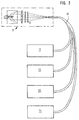
- FIG. 2 deals with the use of the device according to the invention.
- the bundled luminous flux 2 of a discharge lamp 1 is guided through a diffuser 6 and optionally a color filter 8, wherein it is focused on the end face of an optical fiber bundle 10.
- this entire arrangement of the central light source consisting of a discharge lamp 1, a convex lens 4, the diffuser 6 and a color filter 8, is provided with the reference number 9.
- the optical fiber bundle 10 receiving the luminous flux 2 is connected to various displays and operating elements in the vehicle. Displays are, for example, the known instrument cluster 11 for speed and speed, a central information display 12 for various types of messages or a radio 13.
- the operating elements 14 include, for example, those for actuating the ventilation or switches for activation or Deactivation of various vehicle units.
- the color filter 8 shown enables an illumination color according to customer requirements. For all displays 11, 12, 13 and control elements 14 of a vehicle, a color filter 8 can be used to set a uniform color.
- the many lamps that are used today to illuminate the exemplified vehicle facilities are required by a only central light source can be replaced.
- the advantages are: better efficiency of light generation and spatial separation of light generation and lighting needs. The latter helps the inevitable Problem of waste heat when generating light in thermally uncritical To relocate areas.
- the inventive Device of hue for all lighting devices in a simple way centrally adjustable through a single color locator. With conventional Decentralized lighting can hardly be optimally colored be coordinated. For one thing, it differs Light spectrum of the individual light sources from each other. On the other hand, it is decentralized lighting required coordination in the manufacturing process for a vehicle at least not practical because the system components in the Usually be provided by different suppliers.
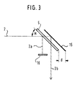
- multiple dimming can be implemented on the diffuser 6 according to the principle of operation described here by means of mirrors suitably arranged on both sides of the diffuser 6.
- the luminous flux reflected on the mirror forms the useful light 2b, whereas a luminous flux reflected by the oblique incidence of light on the surface of the diffuser - the so-called double image 2a - is filtered out through a diaphragm 16 to avoid interference.
- the distance d between the diffuser 6 and the mirror 15 is required for separating the double image from the useful light.
- the device according to the invention for analog and uniform dimming of a light flux guided in an optical beam path leads to the fact that Very little light, for example, on controls on demand can be provided, which is usually for the purpose of search help completely sufficient, whereas large-scale displays like one High luminance can be provided which is still easy to read even in high ambient brightness ensure the displayed messages, but - which is essential - on No heat is generated that is dissipated or generated by the place of the light requirement constructive measures must be taken into account.
- Conventional Illuminants and lighting arrangements have the disadvantage that they on the one hand are not very efficient in terms of their energy balance if at the location of the Light requirement only a low light intensity is required, but on the other hand at higher luminance levels, it quickly heats up selectively to lead. These disadvantages can be overcome by using a central light source be avoided. However, their realization requires that for a high efficient light source, such as a discharge lamp, an analog and uniform dimming is available.
Landscapes
- Physics & Mathematics (AREA)
- General Physics & Mathematics (AREA)
- Optics & Photonics (AREA)
- Engineering & Computer Science (AREA)
- Mechanical Engineering (AREA)
- Non-Portable Lighting Devices Or Systems Thereof (AREA)
- Liquid Crystal (AREA)
- Lighting Device Outwards From Vehicle And Optical Signal (AREA)
Abstract
Description
- Figur 1A bis 1C das Wirkprinzip der Dimmung durch Streuung,
- Figur 2 den Einsatz einer erfindungsgemäßen Vorrichtung als zentrale Lichtquelle in einem Fahrzeug und
- Figur 3 eine Weiterbildung der gefundenen Lösung.
Claims (9)
- Verfahren zur analogen und gleichmäßigen Dimmung eines in einem optischen Strahlengang geführten Lichtstroms einer Entladungslampe, gekennzeichnet durch eine steuerbare Streuung des Lichtstroms.
- Vorrichtung zur Durchführung des Verfahrens nach Anspruch 1, dadurch gekennzeichnet, daß im optischen Strahlengang eines von einer Entladungslampe (1) erzeugten Lichtstroms (2) ein steuerbarer Diffusor (6) angeordnet ist.
- Vorrichtung nach Anspruch 2, dadurch gekennzeichnet, daß der steuerbare Diffusor aus in ihrer Lage elektrisch manipulierbaren Schwebeteilchen in einer transparenten Flüssigkeit besteht.
- Vorrichtung nach Anspruch 2, dadurch gekennzeichnet, daß der steuerbare Diffusor aus einem in einem Polymer eingebetteten Flüssigkristall besteht.
- Vorrichtung nach Anspruch 4, dadurch gekennzeichnet, daß der steuerbare Diffusor aus einer NCAP™ - Folie besteht.
- Vorrichtung nach Anspruch 2, dadurch gekennzeichnet, daß die Entladungslampe eine in einem Fahrzeug angeordnete zentrale Lichtquelle (9) ist.
- Vorrichtung nach Anspruch 2 oder einem der nachfolgenden Ansprüche, dadurch gekennzeichnet, daß im Strahlengang des von der Entladungslampe erzeugten dimmbaren Lichtstroms (2) vor seiner Einkopplung in einen Lichtleiter (3) ein Farbfilter (8) angeordnet ist.
- Vorrichtung nach Anspruch 2 oder einem der nachfolgenden Ansprüche, dadurch gekennzeichnet, daß im Strahlengang des von der Entladungslampe (1) erzeugten Lichtstroms (2) der Diffusor (6) um einen Winkel α von α = 45° zum einfallenden Lichtstrom (2) geneigt angeordnet und parallel im Abstand d zum Diffusor (6) ein Spiegel (15) vorgesehen ist.
- Vorrichtung nach Anspruch 8, dadurch gekennzeichnet, daß ein an der Oberfläche des Diffusors (6) reflektiertes Doppelbild (2a) durch eine Blende (16) ausgefiltert und so vom Nutzlicht (2b) getrennt wird.
Applications Claiming Priority (2)
| Application Number | Priority Date | Filing Date | Title |
|---|---|---|---|
| DE19735585A DE19735585A1 (de) | 1997-08-16 | 1997-08-16 | Verfahren und Vorrichtung zur analogen und gleichmäßigen Dimmung eines in einem optischen Strahlengang geführten Lichtstroms |
| DE19735585 | 1997-08-16 |
Publications (3)
| Publication Number | Publication Date |
|---|---|
| EP0902314A2 true EP0902314A2 (de) | 1999-03-17 |
| EP0902314A3 EP0902314A3 (de) | 2000-01-05 |
| EP0902314B1 EP0902314B1 (de) | 2006-10-04 |
Family
ID=7839195
Family Applications (1)
| Application Number | Title | Priority Date | Filing Date |
|---|---|---|---|
| EP98114514A Expired - Lifetime EP0902314B1 (de) | 1997-08-16 | 1998-08-03 | Beleuchtungseinheit welche eine Vorrichtung zur analogen und gleichmässigen Dimmung eines in einem optischen Strahlengang geführten Lichtstroms aufweist |
Country Status (3)
| Country | Link |
|---|---|
| EP (1) | EP0902314B1 (de) |
| DE (2) | DE19735585A1 (de) |
| ES (1) | ES2270485T3 (de) |
Families Citing this family (4)
| Publication number | Priority date | Publication date | Assignee | Title |
|---|---|---|---|---|
| DE19906754A1 (de) * | 1999-02-17 | 2000-08-31 | Mannesmann Vdo Ag | Anzeigeeinheit |
| DE10110757A1 (de) * | 2001-03-07 | 2002-09-19 | Bayerische Motoren Werke Ag | Bildschirm in einem Kraftfahrzeug |
| DE102021118773A1 (de) | 2021-07-20 | 2023-01-26 | Reichhardt Gmbh Steuerungstechnik | Beleuchtungssystem mit mehreren Leuchten |
| DE102023132238A1 (de) * | 2023-11-20 | 2025-05-22 | Bayerische Motoren Werke Aktiengesellschaft | Lichttextil, Interieurbauteil und Kraftfahrzeug |
Family Cites Families (6)
| Publication number | Priority date | Publication date | Assignee | Title |
|---|---|---|---|---|
| EP0023741A1 (de) * | 1979-08-02 | 1981-02-11 | Koninklijke Philips Electronics N.V. | Elektrophoretische Bildwiedergabevorrichtung |
| ES2189789T3 (es) * | 1991-11-01 | 2003-07-16 | Research Frontiers Inc | Valvula de luz que emplea una pelicula que comprende una suspension liquida encapsulada, y metodo de fabricacion de dicha pelicula. |
| EP0578827B1 (de) * | 1992-01-30 | 2001-05-02 | Nippon Hoso Kyokai | Beleuchtungssystem mit flüssigkristall-lichtregelplatte |
| JPH06281909A (ja) * | 1993-03-26 | 1994-10-07 | A G Technol Kk | 液晶光学装置及びそれを用いた照明装置 |
| DE4439547A1 (de) * | 1994-11-05 | 1996-05-09 | Hella Kg Hueck & Co | Lichtsystem für den Innenraum eines Kraftfahrzeuges |
| US5629996A (en) * | 1995-11-29 | 1997-05-13 | Physical Optics Corporation | Universal remote lighting system with nonimaging total internal reflection beam transformer |
-
1997
- 1997-08-16 DE DE19735585A patent/DE19735585A1/de not_active Withdrawn
-
1998
- 1998-08-03 EP EP98114514A patent/EP0902314B1/de not_active Expired - Lifetime
- 1998-08-03 ES ES98114514T patent/ES2270485T3/es not_active Expired - Lifetime
- 1998-08-03 DE DE59813750T patent/DE59813750D1/de not_active Expired - Fee Related
Also Published As
| Publication number | Publication date |
|---|---|
| ES2270485T3 (es) | 2007-04-01 |
| DE59813750D1 (de) | 2006-11-16 |
| EP0902314B1 (de) | 2006-10-04 |
| EP0902314A3 (de) | 2000-01-05 |
| DE19735585A1 (de) | 1999-02-18 |
Similar Documents
| Publication | Publication Date | Title |
|---|---|---|
| DE112009001681T9 (de) | Flächenprojektionssystem zur Abbildung eines viesuellen Signals auf einer Oberfläche | |
| DE69637426T2 (de) | Polarisierte Anzeige mit hohem Wirkungsgrad | |
| DE69224874T2 (de) | Hintergrundbeleuchtungssystem für elektrooptische Anzeigen | |
| DE19845603C2 (de) | Beleuchtungseinrichtung für ein Mikroskop | |
| DE3789331T2 (de) | Modulierte Beleuchtungsvorrichtung für ein elektro-optisches Display. | |
| EP0278038A1 (de) | Aktiver Bildschirm in Flachbauweise | |
| EP1378771A1 (de) | Innenraumleuchte | |
| EP1347641A1 (de) | Projektionsfreie Anzeigevorrichtung | |
| DE4036199A1 (de) | Fahrzeugbeleuchtungsanordnung, insbesondere fuer motorfahrzeuge | |
| EP0540555B1 (de) | Einrichtung zur beleuchtung mit polarisiertem licht | |
| DE3443567A1 (de) | Fluessigkristall-anzeigeeinrichtung | |
| DE2437580B1 (de) | Signalanzeigevorrichtung zur Ausstrahlung von Lichtzeichen | |
| DE2831174A1 (de) | Leuchtanzeige-vorrichtung | |
| EP0902314B1 (de) | Beleuchtungseinheit welche eine Vorrichtung zur analogen und gleichmässigen Dimmung eines in einem optischen Strahlengang geführten Lichtstroms aufweist | |
| EP0603465B1 (de) | Verfahren und Anordnung zur optischen Darstellung von Informationen | |
| DE102016211691B4 (de) | Vorrichtung und Verfahren zum Erzeugen einer Ausgangslichtemission | |
| EP4198610B1 (de) | Head-up-display bilderzeugungseinheit mit faltspiegel | |
| DE10034484A1 (de) | Vorrichtung zur Ausleuchtung | |
| DE2235201A1 (de) | Verkehrssignallaterne | |
| DE102021123109B4 (de) | Fahrzeugleuchte sowie fahrzeug mit fahrzeugleuchte | |
| DE2160823A1 (de) | Signalgeber fuer optische verkehrssignale | |
| DE19746854A1 (de) | Rettungszeichenleuchte mit Leuchtdioden für den Notbetrieb | |
| EP0451621A2 (de) | Flüssigkristallzellenanordnung | |
| DE3701312A1 (de) | Vorrichtung zur erzeugung eines aus mehreren farbigen leuchtpunkten bestehenden meldebildes auf einem anzeige-tableau | |
| DE102023203713A1 (de) | Beleuchtungseinrichtung für ein Fahrzeug zur Erfüllung einer Lichtfunktion des Fahrzeugs und Verfahren zum Betreiben einer Beleuchtungseinrichtung für ein Fahrzeug |
Legal Events
| Date | Code | Title | Description |
|---|---|---|---|
| PUAI | Public reference made under article 153(3) epc to a published international application that has entered the european phase |
Free format text: ORIGINAL CODE: 0009012 |
|
| AK | Designated contracting states |
Kind code of ref document: A2 Designated state(s): DE ES FR GB |
|
| AX | Request for extension of the european patent |
Free format text: AL;LT;LV;MK;RO;SI |
|
| PUAL | Search report despatched |
Free format text: ORIGINAL CODE: 0009013 |
|
| AK | Designated contracting states |
Kind code of ref document: A3 Designated state(s): AT BE CH CY DE DK ES FI FR GB GR IE IT LI LU MC NL PT SE |
|
| AX | Request for extension of the european patent |
Free format text: AL;LT;LV;MK;RO;SI |
|
| RIC1 | Information provided on ipc code assigned before grant |
Free format text: 7G 02F 1/1333 A, 7G 02F 1/13 B, 7G 02F 1/167 B, 7F 21V 8/00 B, 7G 12B 11/00 B, 7A 61B 1/07 B |
|
| 17P | Request for examination filed |
Effective date: 19991201 |
|
| AKX | Designation fees paid |
Free format text: DE ES FR GB |
|
| RAP1 | Party data changed (applicant data changed or rights of an application transferred) |
Owner name: SIEMENS AKTIENGESELLSCHAFT |
|
| 17Q | First examination report despatched |
Effective date: 20050406 |
|
| GRAP | Despatch of communication of intention to grant a patent |
Free format text: ORIGINAL CODE: EPIDOSNIGR1 |
|
| RTI1 | Title (correction) |
Free format text: DEVICE FOR CONTINUOUS AND UNIFORM DIMMING OF LUMINOUS FLUX IN AN OPTICAL BEAM PATH |
|
| RTI1 | Title (correction) |
Free format text: ILLUMINATION UNIT COMPRISING A DEVICE FOR CONTINUOUS AND UNIFORM DIMMING OF A LUMINOUS FLUX IN AN OPTICAL BEAM PATH |
|
| GRAS | Grant fee paid |
Free format text: ORIGINAL CODE: EPIDOSNIGR3 |
|
| GRAA | (expected) grant |
Free format text: ORIGINAL CODE: 0009210 |
|
| AK | Designated contracting states |
Kind code of ref document: B1 Designated state(s): DE ES FR GB |
|
| REG | Reference to a national code |
Ref country code: GB Ref legal event code: FG4D Free format text: NOT ENGLISH |
|
| REF | Corresponds to: |
Ref document number: 59813750 Country of ref document: DE Date of ref document: 20061116 Kind code of ref document: P |
|
| GBT | Gb: translation of ep patent filed (gb section 77(6)(a)/1977) |
Effective date: 20070103 |
|
| REG | Reference to a national code |
Ref country code: ES Ref legal event code: FG2A Ref document number: 2270485 Country of ref document: ES Kind code of ref document: T3 |
|
| ET | Fr: translation filed | ||
| PLBE | No opposition filed within time limit |
Free format text: ORIGINAL CODE: 0009261 |
|
| STAA | Information on the status of an ep patent application or granted ep patent |
Free format text: STATUS: NO OPPOSITION FILED WITHIN TIME LIMIT |
|
| 26N | No opposition filed |
Effective date: 20070705 |
|
| PGFP | Annual fee paid to national office [announced via postgrant information from national office to epo] |
Ref country code: ES Payment date: 20080828 Year of fee payment: 11 Ref country code: DE Payment date: 20080822 Year of fee payment: 11 |
|
| PGFP | Annual fee paid to national office [announced via postgrant information from national office to epo] |
Ref country code: FR Payment date: 20080813 Year of fee payment: 11 |
|
| PGFP | Annual fee paid to national office [announced via postgrant information from national office to epo] |
Ref country code: GB Payment date: 20080821 Year of fee payment: 11 |
|
| GBPC | Gb: european patent ceased through non-payment of renewal fee |
Effective date: 20090803 |
|
| REG | Reference to a national code |
Ref country code: FR Ref legal event code: ST Effective date: 20100430 |
|
| PG25 | Lapsed in a contracting state [announced via postgrant information from national office to epo] |
Ref country code: FR Free format text: LAPSE BECAUSE OF NON-PAYMENT OF DUE FEES Effective date: 20090831 Ref country code: DE Free format text: LAPSE BECAUSE OF NON-PAYMENT OF DUE FEES Effective date: 20100302 |
|
| REG | Reference to a national code |
Ref country code: ES Ref legal event code: FD2A Effective date: 20090804 |
|
| PG25 | Lapsed in a contracting state [announced via postgrant information from national office to epo] |
Ref country code: GB Free format text: LAPSE BECAUSE OF NON-PAYMENT OF DUE FEES Effective date: 20090803 |
|
| PG25 | Lapsed in a contracting state [announced via postgrant information from national office to epo] |
Ref country code: ES Free format text: LAPSE BECAUSE OF NON-PAYMENT OF DUE FEES Effective date: 20090804 |