EP0902314A2 - Method and device for continuous and uniform dimming of luminous flux in an optical beam path - Google Patents
Method and device for continuous and uniform dimming of luminous flux in an optical beam path Download PDFInfo
- Publication number
- EP0902314A2 EP0902314A2 EP98114514A EP98114514A EP0902314A2 EP 0902314 A2 EP0902314 A2 EP 0902314A2 EP 98114514 A EP98114514 A EP 98114514A EP 98114514 A EP98114514 A EP 98114514A EP 0902314 A2 EP0902314 A2 EP 0902314A2
- Authority
- EP
- European Patent Office
- Prior art keywords
- luminous flux
- diffuser
- beam path
- discharge lamp
- light
- Prior art date
- Legal status (The legal status is an assumption and is not a legal conclusion. Google has not performed a legal analysis and makes no representation as to the accuracy of the status listed.)
- Granted
Links
- 238000000034 method Methods 0.000 title claims abstract description 12
- 230000004907 flux Effects 0.000 title claims description 34
- 230000003287 optical effect Effects 0.000 title claims description 9
- 239000004973 liquid crystal related substance Substances 0.000 claims description 5
- 229920000642 polymer Polymers 0.000 claims description 3
- 239000007788 liquid Substances 0.000 claims description 2
- 239000002245 particle Substances 0.000 claims description 2
- 239000000243 solution Substances 0.000 description 6
- 238000010521 absorption reaction Methods 0.000 description 5
- 238000011161 development Methods 0.000 description 3
- 230000018109 developmental process Effects 0.000 description 3
- 230000005684 electric field Effects 0.000 description 3
- 230000008901 benefit Effects 0.000 description 2
- 239000000463 material Substances 0.000 description 2
- 230000007935 neutral effect Effects 0.000 description 2
- 239000013307 optical fiber Substances 0.000 description 2
- 230000004913 activation Effects 0.000 description 1
- 238000000149 argon plasma sintering Methods 0.000 description 1
- 230000008878 coupling Effects 0.000 description 1
- 238000010168 coupling process Methods 0.000 description 1
- 238000005859 coupling reaction Methods 0.000 description 1
- 230000009849 deactivation Effects 0.000 description 1
- 230000001419 dependent effect Effects 0.000 description 1
- 239000006185 dispersion Substances 0.000 description 1
- 230000000694 effects Effects 0.000 description 1
- 238000005516 engineering process Methods 0.000 description 1
- 239000013305 flexible fiber Substances 0.000 description 1
- 238000005286 illumination Methods 0.000 description 1
- 238000009434 installation Methods 0.000 description 1
- 238000004519 manufacturing process Methods 0.000 description 1
- 238000000386 microscopy Methods 0.000 description 1
- 230000010287 polarization Effects 0.000 description 1
- 230000001105 regulatory effect Effects 0.000 description 1
- 238000000926 separation method Methods 0.000 description 1
- 238000001228 spectrum Methods 0.000 description 1
- 230000007704 transition Effects 0.000 description 1
- 238000002834 transmittance Methods 0.000 description 1
- 238000009423 ventilation Methods 0.000 description 1
- 239000002918 waste heat Substances 0.000 description 1
Images

Classifications
-
- G—PHYSICS
- G02—OPTICS
- G02B—OPTICAL ELEMENTS, SYSTEMS OR APPARATUS
- G02B6/00—Light guides; Structural details of arrangements comprising light guides and other optical elements, e.g. couplings
- G02B6/24—Coupling light guides
- G02B6/42—Coupling light guides with opto-electronic elements
- G02B6/4298—Coupling light guides with opto-electronic elements coupling with non-coherent light sources and/or radiation detectors, e.g. lamps, incandescent bulbs, scintillation chambers
-
- B—PERFORMING OPERATIONS; TRANSPORTING
- B60—VEHICLES IN GENERAL
- B60Q—ARRANGEMENT OF SIGNALLING OR LIGHTING DEVICES, THE MOUNTING OR SUPPORTING THEREOF OR CIRCUITS THEREFOR, FOR VEHICLES IN GENERAL
- B60Q3/00—Arrangement of lighting devices for vehicle interiors; Lighting devices specially adapted for vehicle interiors
- B60Q3/60—Arrangement of lighting devices for vehicle interiors; Lighting devices specially adapted for vehicle interiors characterised by optical aspects
- B60Q3/62—Arrangement of lighting devices for vehicle interiors; Lighting devices specially adapted for vehicle interiors characterised by optical aspects using light guides
- B60Q3/66—Arrangement of lighting devices for vehicle interiors; Lighting devices specially adapted for vehicle interiors characterised by optical aspects using light guides for distributing light among several lighting devices
-
- B60K2360/33—
-
- G—PHYSICS
- G02—OPTICS
- G02F—OPTICAL DEVICES OR ARRANGEMENTS FOR THE CONTROL OF LIGHT BY MODIFICATION OF THE OPTICAL PROPERTIES OF THE MEDIA OF THE ELEMENTS INVOLVED THEREIN; NON-LINEAR OPTICS; FREQUENCY-CHANGING OF LIGHT; OPTICAL LOGIC ELEMENTS; OPTICAL ANALOGUE/DIGITAL CONVERTERS
- G02F1/00—Devices or arrangements for the control of the intensity, colour, phase, polarisation or direction of light arriving from an independent light source, e.g. switching, gating or modulating; Non-linear optics
- G02F1/01—Devices or arrangements for the control of the intensity, colour, phase, polarisation or direction of light arriving from an independent light source, e.g. switching, gating or modulating; Non-linear optics for the control of the intensity, phase, polarisation or colour
- G02F1/13—Devices or arrangements for the control of the intensity, colour, phase, polarisation or direction of light arriving from an independent light source, e.g. switching, gating or modulating; Non-linear optics for the control of the intensity, phase, polarisation or colour based on liquid crystals, e.g. single liquid crystal display cells
- G02F1/133—Constructional arrangements; Operation of liquid crystal cells; Circuit arrangements
- G02F1/1333—Constructional arrangements; Manufacturing methods
- G02F1/1334—Constructional arrangements; Manufacturing methods based on polymer dispersed liquid crystals, e.g. microencapsulated liquid crystals
Definitions
- the invention relates to a method for analog and uniform dimming of a light flux guided in an optical beam path according to the Preamble of the first claim and an apparatus for performing the Procedure.
- Discharge lamps such as those from the company's XENARC ⁇ series OSRAM are highly efficient lamps with a high efficiency of approx. 90 lm / W. However, according to current knowledge, they are not electrical dimmable.
- the luminous flux is one Discharge lamp is regulated by absorption.
- This can, for example, under Use an aperture or a neutral filter.
- Procedures that act absorptive but have the disadvantage of not being both at the same time to be controllable analogously as well as being capable of uniform dimming.
- a neutral filter it is possible with even absorption over the uniform dimming can be achieved across the entire absorption surface, however, analog control of absorption is not possible at the same time.
- the luminous flux is passed through a gray wedge, for example, it can be dimmed by the position of the gray wedge in the beam path, but only with uneven absorption in the effective range.
- Luminous flux generated by a discharge lamp is a controllable diffuser to be ordered.
- This controllable diffuser can be in place electrically manipulable suspended particles in a transparent liquid exist or a liquid crystal embedded in a transparent polymer be.
- a particularly advantageous one results in vehicle technology Use of the proposed method and the device for Carrying out the method, for example, when the discharge lamp is a central light source located in a vehicle. Without This example is intended to limit the application to this application are explained in more detail. Other applications are for example in Connection with cold light sources in microscopy or at Given endoscopic lighting.
- a discharge lamp 1 generates a luminous flux 2, which is guided as a parallel beam of rays by means which are only indicated in a hint.
- a convex lens 4 is arranged in the beam path and focuses the beam onto the end face 5 of the light guide 3.
- a controllable diffuser 6 is arranged in the beam path at a certain distance D from the end face 5 of the light guide 3.
- the Distance D in relation to the cross-section of that guided in the beam Luminous flux 2 and in relation to the geometry of the rest of the To dimension the device involved components appropriately, so that the light deflected at the scattering centers 7a, 7b, 7c, 7d and 7e also actually leads past the end face 5 of the light guide 3.
- the diffuser 6 by an external electrical to be applied to it Field in its optical properties, that is its transparency influence.
- Luminous flux 2 can be controlled analogously in a simple manner.
- the diffuser is 6 through its structure and the choice of materials so that it can be designed its entire optically active surface has a uniform dispersion incident light flux 2 generated.
- NCAP TM film which consists of a liquid crystal embedded in a polymer, has proven to be advantageous here, as shown in FIG. 1C .
- an NCAP TM film works without polarization.
- the encapsulated molecules of the liquid crystal align in the direction of the electrical field. This makes the film transparent. Luminous flux passing through it remains convergent.
- the orientation of the molecules of the liquid crystal is statistically distributed, so that incident light is scattered in the material. The transition from the scattering to the transparent state can be controlled analogously depending on the applied electric field.
- FIG. 2 deals with the use of the device according to the invention.
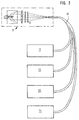
- the bundled luminous flux 2 of a discharge lamp 1 is guided through a diffuser 6 and optionally a color filter 8, wherein it is focused on the end face of an optical fiber bundle 10.
- this entire arrangement of the central light source consisting of a discharge lamp 1, a convex lens 4, the diffuser 6 and a color filter 8, is provided with the reference number 9.
- the optical fiber bundle 10 receiving the luminous flux 2 is connected to various displays and operating elements in the vehicle. Displays are, for example, the known instrument cluster 11 for speed and speed, a central information display 12 for various types of messages or a radio 13.
- the operating elements 14 include, for example, those for actuating the ventilation or switches for activation or Deactivation of various vehicle units.
- the color filter 8 shown enables an illumination color according to customer requirements. For all displays 11, 12, 13 and control elements 14 of a vehicle, a color filter 8 can be used to set a uniform color.
- the many lamps that are used today to illuminate the exemplified vehicle facilities are required by a only central light source can be replaced.
- the advantages are: better efficiency of light generation and spatial separation of light generation and lighting needs. The latter helps the inevitable Problem of waste heat when generating light in thermally uncritical To relocate areas.
- the inventive Device of hue for all lighting devices in a simple way centrally adjustable through a single color locator. With conventional Decentralized lighting can hardly be optimally colored be coordinated. For one thing, it differs Light spectrum of the individual light sources from each other. On the other hand, it is decentralized lighting required coordination in the manufacturing process for a vehicle at least not practical because the system components in the Usually be provided by different suppliers.
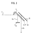
- multiple dimming can be implemented on the diffuser 6 according to the principle of operation described here by means of mirrors suitably arranged on both sides of the diffuser 6.
- the luminous flux reflected on the mirror forms the useful light 2b, whereas a luminous flux reflected by the oblique incidence of light on the surface of the diffuser - the so-called double image 2a - is filtered out through a diaphragm 16 to avoid interference.
- the distance d between the diffuser 6 and the mirror 15 is required for separating the double image from the useful light.
- the device according to the invention for analog and uniform dimming of a light flux guided in an optical beam path leads to the fact that Very little light, for example, on controls on demand can be provided, which is usually for the purpose of search help completely sufficient, whereas large-scale displays like one High luminance can be provided which is still easy to read even in high ambient brightness ensure the displayed messages, but - which is essential - on No heat is generated that is dissipated or generated by the place of the light requirement constructive measures must be taken into account.
- Conventional Illuminants and lighting arrangements have the disadvantage that they on the one hand are not very efficient in terms of their energy balance if at the location of the Light requirement only a low light intensity is required, but on the other hand at higher luminance levels, it quickly heats up selectively to lead. These disadvantages can be overcome by using a central light source be avoided. However, their realization requires that for a high efficient light source, such as a discharge lamp, an analog and uniform dimming is available.
Abstract
Description
Die Erfindung betrifft ein Verfahren zur analogen und gleichmäßigen Dimmung eines in einem optischen Strahlengang geführten Lichtstroms gemäß dem Oberbegriff des ersten Anspruchs sowie eine Vorrichtung zur Durchführung des Verfahrens.The invention relates to a method for analog and uniform dimming of a light flux guided in an optical beam path according to the Preamble of the first claim and an apparatus for performing the Procedure.
Entladungslampen, wie zum Beispiel die aus der XENARC© - Reihe der Firma OSRAM, sind hocheffiziente Leuchtmittel mit einem hohen Wirkungsgrad von ca. 90 lm/W. Jedoch sind sie nach heutigem Kenntnisstand elektrisch nicht dimmbar.Discharge lamps, such as those from the company's XENARC © series OSRAM are highly efficient lamps with a high efficiency of approx. 90 lm / W. However, according to current knowledge, they are not electrical dimmable.
Bekannt sind vielmehr Verfahren, bei denen der Lichtstrom einer Entladungslampe durch Absorption geregelt wird. Dies kann zum Beispiel unter Verwendung einer Blende oder eines Neutralfilters geschehen. Verfahren, die absorptiv wirken, haben aber den Nachteil, nicht gleichzeitig sowohl zu einer analog steuerbaren als auch zu einer gleichmäßigen Dimmung fähig zu sein. Mit einem Neutralfilter kann zwar bei gleichmäßiger Absorption über die gesamte Absorptionsfläche eine gleichmäßige Dimmung erreicht werden, jedoch ist nicht gleichzeitig eine analoge Steuerung der Absorption möglich. Wird andererseits der Lichtstrom beispielsweise durch einen Graukeil geführt, ist er zwar durch die Stellung des Graukeils im Strahlengang analog dimmbar, jedoch nur mit einer ungleichmäßigen Absorption im wirksamen Bereich. Rather, methods are known in which the luminous flux is one Discharge lamp is regulated by absorption. This can, for example, under Use an aperture or a neutral filter. Procedures that act absorptive, but have the disadvantage of not being both at the same time to be controllable analogously as well as being capable of uniform dimming. With a neutral filter it is possible with even absorption over the uniform dimming can be achieved across the entire absorption surface, however, analog control of absorption is not possible at the same time. On the other hand, if the luminous flux is passed through a gray wedge, for example, it can be dimmed by the position of the gray wedge in the beam path, but only with uneven absorption in the effective range.
Denkbar wäre es, einen von einer Entladungslampe erzeugten Lichtstrom mit einer herkömmlichen LCD-Zelle absorptiv zu dimmen. Hierbei gehen jedoch schon allein durch den ersten Polarisator der LCD-Zelle mindestens 50 % des nutzbaren Lichts verloren, so daß die Lichtdurchlässigkeit der LCD-Zelle ein beachtliches Problem darstellt. Der verbleibende Lichtstrom ist dann zwar in den Grenzen des maximalem Kontrastes der LCD-Zelle steuerbar, jedoch ist nachteilig, daß die LCD-Zelle aufgrund ihrer elektrooptischen Kennlinie eine ungleichmäßige Lichtverteilung verursacht.It would be conceivable to include a luminous flux generated by a discharge lamp dimming a conventional LCD cell absorptively. Here, however, go by the first polarizer of the LCD cell alone at least 50% of the usable light is lost, so that the light transmittance of the LCD cell represents a considerable problem. The remaining luminous flux is then in the limits of the maximum contrast of the LCD cell can be controlled, however disadvantageous that the LCD cell due to its electro-optical characteristic causes uneven light distribution.
Es ist nun die Aufgabe der vorliegenden Erfindung, ein Verfahren zur analogen und gleichmäßigen Dimmung eines in einem optischen Strahlengang geführten Lichtstroms einer Entladungslampe aufzuzeigen sowie eine Vorrichtung zur Durchführung des Verfahrens bereitzustellen.It is now the object of the present invention, a method for analog and uniform dimming of one guided in an optical beam path To show luminous flux of a discharge lamp and a device for To provide implementation of the procedure.
Die Aufgabe wird durch die Merkmale des ersten und zweiten Anspruchs gelöst. Die abhängigen Ansprüche zeigen vorteilhafte Weiterbildungen und Ausgestaltungen der gefundenen Lösung.The object is achieved by the features of the first and second claims solved. The dependent claims show advantageous developments and Refinements of the solution found.
Die gefundene Lösung schlägt vor, die Dimmung des Lichtstroms durch eine steuerbare Streuung vorzunehmen. Dazu soll im optischen Strahlengang eines von einer Entladungslampe erzeugten Lichtstroms ein steuerbarer Diffusor angeordnet werden. Dieser steuerbare Diffusor kann aus in ihrer Lage elektrisch manipulierbaren Schwebeteilchen in einer transparenten Flüssigkeit bestehen oder ein in einem transparenten Polymer eingebetteter Flüssigkristall sein. In der Fahrzeugtechnik ergibt sich eine besonders vorteilhafte Verwendung des vorgeschlagenen Verfahrens und der Vorrichtung zur Durchführung des Verfahrens beispielsweise dann, wenn die Entladungslampe eine in einem Fahrzeug angeordnete zentrale Lichtquelle ist. Ohne Beschränkung auf diese Anwendung soll die Erfindung an diesem Beispiel näher erläutert werden. Andere Anwendungen sind beispielsweise in Verbindung mit Kaltlichtquellen in der Mikroskopie oder bei Endoskopiebeleuchtungen gegeben.The solution found suggests dimming the luminous flux through a to make controllable spread. For this purpose, one in the optical beam path Luminous flux generated by a discharge lamp is a controllable diffuser to be ordered. This controllable diffuser can be in place electrically manipulable suspended particles in a transparent liquid exist or a liquid crystal embedded in a transparent polymer be. A particularly advantageous one results in vehicle technology Use of the proposed method and the device for Carrying out the method, for example, when the discharge lamp is a central light source located in a vehicle. Without This example is intended to limit the application to this application are explained in more detail. Other applications are for example in Connection with cold light sources in microscopy or at Given endoscopic lighting.
Zur Verdeutlichung der Erfindung sind drei Figuren beigefügt. Es zeigen
- Figur 1A bis 1C das Wirkprinzip der Dimmung durch Streuung,
-
Figur 2 den Einsatz einer erfindungsgemäßen Vorrichtung als zentrale Lichtquelle in einem Fahrzeug und -
Figur 3 eine Weiterbildung der gefundenen Lösung.
- 1A to 1C, the principle of operation of dimming by scattering,
- Figure 2 shows the use of a device according to the invention as a central light source in a vehicle and
- Figure 3 is a further development of the solution found.
Gemäß der Darstellung in der Figur 1A erzeugt eine Entladungslampe 1 einen
Lichtstrom 2, der durch nur andeutungsweise dargestellte Mittel als ein
paralleles Strahlenbündel geführt wird. Um den Lichtstrom 2 beispielsweise in
einen Lichtleiter 3 einzukoppeln, ist im Strahlengang eine konvexe Linse 4
angeordnet, die das Strahlenbündel auf die Stirnfläche 5 des Lichtleiters 3
fokussiert. Zur Dimmung des Lichtstroms 2 befindet sich im Strahlengang in
einem gewissen Abstand D zur Stirnfläche 5 des Lichtleiters 3 ein steuerbarer
Diffusor 6. Es steht dem Fachmann frei, statt eines Lichtleiters 3 auch einen
anderen Lichtaufnehmer, wie z.B. ein flexibles Faserbündel zu verwenden.According to the illustration in FIG. 1A , a
Durch Manipulation der optischen Eigenschaften des Diffusors 6 läßt dieser,
wie in der Figur 1B dargestellt, Streuzentren, z. B. 7a, 7b, 7c, 7d und 7e
entstehen, die den konvergenten Strahlenverlauf zunehmend in einen
divergenten verwandeln. Die Streuung des Lichtbündels am Diffusor 6 bewirkt,
daß nur noch ein verringerter Teil des Lichtstroms 2 auf die Stirnfläche 5 des
Lichtleiters 3 trifft und dort eingekoppelt wird. Der übrige Teil des Lichtstroms 2
wird jedoch nicht absorbiert und damit in Wärme umgewandelt, sondern
lediglich in seiner Richtung abgelenkt. Es ist ein besonderer Vorteil der
vorgeschlagenen Lösung, daß sie keine thermischen Probleme verursacht. By manipulating the optical properties of the
Zur wirksamen Verringerung der Lichteinkopplung in den Lichtleiter 3 ist der
Abstand D im Verhältnis zum Querschnitt des im Strahlenbündel geführten
Lichtstroms 2 sowie im Verhältnis zur Geometrie der übrigen an der
Vorrichtung beteiligten Komponenten angemessen zu dimensionieren, so daß
das an den Streuzentren 7a, 7b, 7c, 7d und 7e abgelenkte Licht auch
tatsächlich an der Stirnfläche 5 des Lichtleiters 3 vorbeiführt. Der Abstand D
zwischen dem lichtstreuenden Element - dem Diffusor 6 - und dem
Lichtaufnehmer, z. B. dem Uchtleiter 3, bestimmt das maximale
Dimmverhältnis.To effectively reduce the coupling of light into the
Es ist vorteilhaft und die bevorzugte Ausgestaltung der vorgeschlagenen
Vorrichtung, den Diffusor 6 durch ein an ihn anlegbares äußeres elektrisches
Feld in seinen optischen Eigenschaften, das heißt seiner Transparenz zu
beeinflussen. Durch eine elektrische Beeinflußbarkeit des Diffusors 6 wird der
Lichtstrom 2 auf einfache Weise analog steuerbar. Überdies ist der Diffusor 6
durch seinen Aufbau und die Werkstoffauswahl so gestaltbar, daß er über
seine gesamte optisch aktive Fläche eine gleichmäßige Streuung eines
einfallenden Lichtstroms 2 erzeugt.It is advantageous and the preferred embodiment of the proposed
Device, the
Als vorteilhaft hat sich hier beispielsweise eine NCAP™ - Folie erwiesen, die aus einem in einem Polymer eingebetteten Flüssigkristall besteht, was in der Figur 1C dargestellt ist. Eine NCAP™ - Folie arbeitet im Gegensatz zu herkömmlichen LCD Zellen ohne Polarisation. Beim Anlegen einer elektrischen Spannung U richten sich die gekapselten Moleküle des Flüssigkristalls in Richtung des elektrischen Feldes aus. Dadurch wird die Folie transparent. Ein durch sie hindurchtretender Lichtstrom bleibt konvergent. In Abwesenheit eines elektrischen Feldes sind die Moleküle des Flüssigkristalls hingegen in ihrer Ausrichtung statistisch verteilt, so daß einfallendes Licht im Material gestreut wird. Der Übergang vom streuenden in den transparenten Zustand läßt sich in Abhängigkeit vom anliegenden elektrischen Feld analog steuern.An NCAP ™ film, which consists of a liquid crystal embedded in a polymer, has proven to be advantageous here, as shown in FIG. 1C . In contrast to conventional LCD cells, an NCAP ™ film works without polarization. When an electrical voltage U is applied, the encapsulated molecules of the liquid crystal align in the direction of the electrical field. This makes the film transparent. Luminous flux passing through it remains convergent. In the absence of an electric field, however, the orientation of the molecules of the liquid crystal is statistically distributed, so that incident light is scattered in the material. The transition from the scattering to the transparent state can be controlled analogously depending on the applied electric field.
Die Figur 2 geht auf eine Verwendung der erfindungsgemäßen Vorrichtung
ein. Der gebündelte Lichtstrom 2 einer Entladungslampe 1 wird durch einen
Diffusor 6 und gegebenenfalls einen Farbfilter 8 geführt, wobei er auf die
Stirnfläche eines Lichtleitfaserbündels 10 fokussiert ist. In der Figur 2 ist diese
gesamte Anordnung der zentralen Lichtquelle, bestehend aus einer
Entladungslampe 1, einer konvexen Linse 4, dem Diffusor 6 und einem
Farbfilter 8 mit dem Bezugszeichen 9 versehen. Das den Lichtstrom 2
aufnehmende Lichtleitfaserbündel 10 ist mit diversen Anzeigen und
Bedienelementen im Fahrzeug verbunden. Anzeigen sind beispielsweise das
bekannte Kombiinstrument 11 für Geschwindigkeit und Drehzahl, ein zentrales
Informationsdisplay 12 für Meldungen unterschiedlichster Art oder ein Radio
13. Zu den (nicht im einzelnen dargestellten) Bedienelementen 14 zählen zum
Beispiel diejenigen für die Betätigung der Lüftung oder Schalter zur Aktivierung
bzw. Deaktivierung verschiedener Fahrzeugaggregate. Das gezeigte Farbfilter
8 ermöglicht eine Beleuchtungsfarbe nach Kundenwunsch. Für alle Anzeigen
11, 12, 13 und Bedienelemente 14 eines Fahrzeugs kann durch dieses eine
Farbfilter 8 ein einheitlicher Farbton eingestellt werden. FIG. 2 deals with the use of the device according to the invention. The bundled
Es ist vorteilhaft, wenn die vielen Leuchtmittel, die heute zur Beleuchtung der beispielhaft genannten Fahrzeugeinrichtungen benötigt werden, durch eine einzige zentrale Lichtquelle ersetzt werden können. Dabei liegen die Vorteile in einer besseren Effizienz der Lichterzeugung sowie der räumlichen Trennung von Lichterzeugung und Lichtbedarf. Letzteres hilft, das unvermeidliche Problem der Abwärme bei der Lichterzeugung in thermisch unkritische Bereiche zu verlagern. Darüber hinaus ist bei der erfindungsgemäßen Vorrichtung der Farbton für alle Beleuchtungseinrichtungen auf einfache Weise durch eine einzige Farbortbestimmung zentral einstellbar. Bei herkömmlichen dezentralen Beleuchtungen kann der Farbton nur schwerlich optimal aufeinander abgestimmt werden. Zum einen unterscheidet sich das Lichtspektrum der einzelnen Lichtquellen voneinander. Zum anderen ist die bei dezentralen Beleuchtungen erforderliche Abstimmung im Fertigungsprozeß für ein Fahrzeug zumindest nicht praktikabel, da die Systemkomponenten in der Regel von unterschiedlichen Zulieferern beigestellt werden.It is advantageous if the many lamps that are used today to illuminate the exemplified vehicle facilities are required by a only central light source can be replaced. The advantages are: better efficiency of light generation and spatial separation of light generation and lighting needs. The latter helps the inevitable Problem of waste heat when generating light in thermally uncritical To relocate areas. In addition, the inventive Device of hue for all lighting devices in a simple way centrally adjustable through a single color locator. With conventional Decentralized lighting can hardly be optimally colored be coordinated. For one thing, it differs Light spectrum of the individual light sources from each other. On the other hand, it is decentralized lighting required coordination in the manufacturing process for a vehicle at least not practical because the system components in the Usually be provided by different suppliers.
Die Figur 3 zeigt eine Weiterbildung der gefundenen Lösung, die vorteilhaft in
Verbindung mit einer zentralen Lichtquelle in einem Fahrzeug genutzt werden
kann. Es handelt sich dabei um eine Anordnung, um auf engstem Raum eine
Mehrfachdimmung des Lichtstromes zu erreichen. Wenn der von der
Entladungslampe 1 erzeugte Lichtstrom 2 sehr stark gedimmt werden soll, ist
es gerade bei Anordnungen mit sehr begrenztem Bauraum vorteilhaft, den
Diffusor 6 im Winkel a von vorzugsweise α = 45° zum einfallenden Lichtstrom 2
geneigt anzuordnen und parallel, vorzugsweise planparallel im Abstand d zum
Diffusor 6 einen Spiegel 15 vorzusehen. Der Spiegel 15 lenkt den einfallenden
Lichtstrom 2 um und leitet ihn dadurch erneut durch den Diffusor 6. So wird der
Lichtstrom 2 durch ein und denselben Diffusor 6 zweimal gedimmt. Soweit es
nötig ist, lassen sich nach dem hier beschriebenen Wirkprinzip durch beidseitig
des Diffusors 6 geeignet angeordnete Spiegel Mehrfachdimmungen am
Diffusor 6 realisieren. Der am Spiegel reflektierte Lichtstrom bildet das Nutzlicht
2b, wohingegen ein durch den schrägen Lichteinfall an der Oberfläche des
Diffusors reflektierter Lichtstrom - das sogenannte Doppelbild 2a - zur
Vermeidung von Störungen durch eine Blende 16 ausgefiltert wird. Der
Abstand d zwischen dem Diffusor 6 und dem Spiegel 15 ist für eine Trennung
des Doppelbildes vom Nutzlicht erforderlich. FIG. 3 shows a further development of the solution found, which can advantageously be used in connection with a central light source in a vehicle. It is an arrangement to achieve multiple dimming of the luminous flux in a confined space. If the
Die erfindungsgemäße Vorrichtung zur analogen und gleichmäßigen Dimmung eines in einem optischen Strahlengang geführten Lichtstroms führt dazu, daß bedarfsgerecht zum Beispiel an Bedienelementen sehr wenig Licht bereitgestellt werden kann, was in aller Regel für den Zweck der Suchhilfe völlig ausreicht, wohingegen an großflächigen Anzeigen wie einem Informationsdisplay hohe Leuchtdichten zur Verfügung gestellt werden können, die selbst bei einer hohen Umgebungshelligkeit noch eine gute Ablesbarkeit der angezeigten Meldungen sicherstellen, wobei aber - was wesentlich ist - am Ort des Lichtbedarfs keine Wärme erzeugt wird, die abgeführt oder der durch konstruktive Maßnahmen Rechnung getragen werden muß. Herkömmliche Leuchtmittel und Beleuchtungsanordnungen haben den Nachteil, daß sie einerseits in ihrer Energiebilanz wenig effizient sind, wenn am Ort des Lichtbedarfs nur eine geringe Lichtstärke erforderlich ist, sie andererseits aber bei höheren Leuchtdichten schnell zu einer punktuell starken Erwärmung führen. Diese Nachteile können durch den Einsatz einer zentralen Lichtquelle vermieden werden. Ihre Realisierung setzt jedoch voraus, daß für eine hoch effiziente Lichtquelle, wie eine Entladungslampe, eine analoge und gleichmäßige Dimmung zur Verfügung steht.The device according to the invention for analog and uniform dimming of a light flux guided in an optical beam path leads to the fact that Very little light, for example, on controls on demand can be provided, which is usually for the purpose of search help completely sufficient, whereas large-scale displays like one High luminance can be provided which is still easy to read even in high ambient brightness ensure the displayed messages, but - which is essential - on No heat is generated that is dissipated or generated by the place of the light requirement constructive measures must be taken into account. Conventional Illuminants and lighting arrangements have the disadvantage that they on the one hand are not very efficient in terms of their energy balance if at the location of the Light requirement only a low light intensity is required, but on the other hand at higher luminance levels, it quickly heats up selectively to lead. These disadvantages can be overcome by using a central light source be avoided. However, their realization requires that for a high efficient light source, such as a discharge lamp, an analog and uniform dimming is available.
Claims (9)
Applications Claiming Priority (2)
| Application Number | Priority Date | Filing Date | Title |
|---|---|---|---|
| DE19735585 | 1997-08-16 | ||
| DE19735585A DE19735585A1 (en) | 1997-08-16 | 1997-08-16 | Discharge lamp light dimming |
Publications (3)
| Publication Number | Publication Date |
|---|---|
| EP0902314A2 true EP0902314A2 (en) | 1999-03-17 |
| EP0902314A3 EP0902314A3 (en) | 2000-01-05 |
| EP0902314B1 EP0902314B1 (en) | 2006-10-04 |
Family
ID=7839195
Family Applications (1)
| Application Number | Title | Priority Date | Filing Date |
|---|---|---|---|
| EP98114514A Expired - Lifetime EP0902314B1 (en) | 1997-08-16 | 1998-08-03 | Illumination unit comprising a device for continuous and uniform dimming of a luminous flux in an optical beam path |
Country Status (3)
| Country | Link |
|---|---|
| EP (1) | EP0902314B1 (en) |
| DE (2) | DE19735585A1 (en) |
| ES (1) | ES2270485T3 (en) |
Families Citing this family (3)
| Publication number | Priority date | Publication date | Assignee | Title |
|---|---|---|---|---|
| DE19906754A1 (en) * | 1999-02-17 | 2000-08-31 | Mannesmann Vdo Ag | Display unit |
| DE10110757A1 (en) * | 2001-03-07 | 2002-09-19 | Bayerische Motoren Werke Ag | Attachment for a screen display surface in a motor vehicle, consists of a light transparent hollow chamber filled with a light transparent material |
| DE102021118773A1 (en) | 2021-07-20 | 2023-01-26 | Reichhardt Gmbh Steuerungstechnik | Lighting system with multiple lights |
Citations (6)
| Publication number | Priority date | Publication date | Assignee | Title |
|---|---|---|---|---|
| EP0023741A1 (en) * | 1979-08-02 | 1981-02-11 | Koninklijke Philips Electronics N.V. | Electrophoretic image display device |
| WO1993009460A1 (en) * | 1991-11-01 | 1993-05-13 | Research Frontiers Incorporated | Light valve employing a film comprising an encapsulated liquid suspension, and method of making such film |
| EP0578827A1 (en) * | 1992-01-30 | 1994-01-19 | Nippon Hoso Kyokai | Liquid crystal light regulating plate and illuminator including the same |
| JPH06281909A (en) * | 1993-03-26 | 1994-10-07 | A G Technol Kk | Liquid crystal optical device and illuminator using it |
| US5629996A (en) * | 1995-11-29 | 1997-05-13 | Physical Optics Corporation | Universal remote lighting system with nonimaging total internal reflection beam transformer |
| US5647657A (en) * | 1994-11-05 | 1997-07-15 | Hella Kg Hueck & Co. | Light system for an interior of a motor vehicle |
-
1997
- 1997-08-16 DE DE19735585A patent/DE19735585A1/en not_active Withdrawn
-
1998
- 1998-08-03 EP EP98114514A patent/EP0902314B1/en not_active Expired - Lifetime
- 1998-08-03 ES ES98114514T patent/ES2270485T3/en not_active Expired - Lifetime
- 1998-08-03 DE DE59813750T patent/DE59813750D1/en not_active Expired - Fee Related
Patent Citations (6)
| Publication number | Priority date | Publication date | Assignee | Title |
|---|---|---|---|---|
| EP0023741A1 (en) * | 1979-08-02 | 1981-02-11 | Koninklijke Philips Electronics N.V. | Electrophoretic image display device |
| WO1993009460A1 (en) * | 1991-11-01 | 1993-05-13 | Research Frontiers Incorporated | Light valve employing a film comprising an encapsulated liquid suspension, and method of making such film |
| EP0578827A1 (en) * | 1992-01-30 | 1994-01-19 | Nippon Hoso Kyokai | Liquid crystal light regulating plate and illuminator including the same |
| JPH06281909A (en) * | 1993-03-26 | 1994-10-07 | A G Technol Kk | Liquid crystal optical device and illuminator using it |
| US5647657A (en) * | 1994-11-05 | 1997-07-15 | Hella Kg Hueck & Co. | Light system for an interior of a motor vehicle |
| US5629996A (en) * | 1995-11-29 | 1997-05-13 | Physical Optics Corporation | Universal remote lighting system with nonimaging total internal reflection beam transformer |
Non-Patent Citations (1)
| Title |
|---|
| PATENT ABSTRACTS OF JAPAN vol. 1995, no. 01, 28. Februar 1995 (1995-02-28) -& JP 06 281909 A (A G TECHNOL KK), 7. Oktober 1994 (1994-10-07) * |
Also Published As
| Publication number | Publication date |
|---|---|
| DE19735585A1 (en) | 1999-02-18 |
| EP0902314B1 (en) | 2006-10-04 |
| EP0902314A3 (en) | 2000-01-05 |
| DE59813750D1 (en) | 2006-11-16 |
| ES2270485T3 (en) | 2007-04-01 |
Similar Documents
| Publication | Publication Date | Title |
|---|---|---|
| DE69637426T2 (en) | Polarized display with high efficiency | |
| DE112009001681T9 (en) | Surface projection system for imaging a video signal on a surface | |
| DE69725124T2 (en) | METHOD AND DEVICE FOR LIGHT CONTROL | |
| DE19845603C2 (en) | Illumination device for a microscope | |
| EP0278038A1 (en) | Active flat type display panel | |
| EP1378771A1 (en) | Interior lighting | |
| EP1347641A1 (en) | Free projection display device | |
| DE10245933A1 (en) | Device for generating a bundled luminous flux | |
| DE4036199A1 (en) | VEHICLE LIGHTING ARRANGEMENT, IN PARTICULAR FOR MOTOR VEHICLES | |
| DE102009011908A1 (en) | Head-up display and vehicle | |
| EP0540555B1 (en) | Polarized light lighting device | |
| DE2437580C2 (en) | Signal display device for the emission of light signals | |
| DE2831174A1 (en) | Optical display using fibre optics - has light signals transmitted to bulbs on display table through fibre optic links | |
| EP0902314B1 (en) | Illumination unit comprising a device for continuous and uniform dimming of a luminous flux in an optical beam path | |
| DE102016211691B4 (en) | Apparatus and method for generating an output light emission | |
| EP0603465B1 (en) | Method and device for optical presentation of information | |
| DE19723208A1 (en) | Device for modulating the intensity of a light beam, a manufacturing method therefor, a method for modulating the intensity of a light beam, and uses of the device | |
| DE10034484A1 (en) | Illumination device e.g. for motor vehicle has electro-optical elements individually controlled to control light distribution | |
| DE2235201A1 (en) | TRAFFIC SIGNAL LANTERN | |
| DE102021123109B4 (en) | VEHICLE LIGHT AND VEHICLE WITH VEHICLE LIGHT | |
| DE19746854A1 (en) | Escape indication light with light emitting diodes for emergency operation | |
| DE2160823A1 (en) | SIGNAL GENERATOR FOR OPTICAL TRAFFIC SIGNALS | |
| DE3701312A1 (en) | Device for producing on an indicator board a mimic diagram comprising a plurality of coloured illuminated dots | |
| EP4328664A1 (en) | Method and apparatus for optionally rendering an image mirror or an image representation | |
| WO2002099772A2 (en) | Method for modifying the radiating properties in a planar light-guiding transparent body and devices comprising said bodies |
Legal Events
| Date | Code | Title | Description |
|---|---|---|---|
| PUAI | Public reference made under article 153(3) epc to a published international application that has entered the european phase |
Free format text: ORIGINAL CODE: 0009012 |
|
| AK | Designated contracting states |
Kind code of ref document: A2 Designated state(s): DE ES FR GB |
|
| AX | Request for extension of the european patent |
Free format text: AL;LT;LV;MK;RO;SI |
|
| PUAL | Search report despatched |
Free format text: ORIGINAL CODE: 0009013 |
|
| AK | Designated contracting states |
Kind code of ref document: A3 Designated state(s): AT BE CH CY DE DK ES FI FR GB GR IE IT LI LU MC NL PT SE |
|
| AX | Request for extension of the european patent |
Free format text: AL;LT;LV;MK;RO;SI |
|
| RIC1 | Information provided on ipc code assigned before grant |
Free format text: 7G 02F 1/1333 A, 7G 02F 1/13 B, 7G 02F 1/167 B, 7F 21V 8/00 B, 7G 12B 11/00 B, 7A 61B 1/07 B |
|
| 17P | Request for examination filed |
Effective date: 19991201 |
|
| AKX | Designation fees paid |
Free format text: DE ES FR GB |
|
| RAP1 | Party data changed (applicant data changed or rights of an application transferred) |
Owner name: SIEMENS AKTIENGESELLSCHAFT |
|
| 17Q | First examination report despatched |
Effective date: 20050406 |
|
| GRAP | Despatch of communication of intention to grant a patent |
Free format text: ORIGINAL CODE: EPIDOSNIGR1 |
|
| RTI1 | Title (correction) |
Free format text: DEVICE FOR CONTINUOUS AND UNIFORM DIMMING OF LUMINOUS FLUX IN AN OPTICAL BEAM PATH |
|
| RTI1 | Title (correction) |
Free format text: ILLUMINATION UNIT COMPRISING A DEVICE FOR CONTINUOUS AND UNIFORM DIMMING OF A LUMINOUS FLUX IN AN OPTICAL BEAM PATH |
|
| GRAS | Grant fee paid |
Free format text: ORIGINAL CODE: EPIDOSNIGR3 |
|
| GRAA | (expected) grant |
Free format text: ORIGINAL CODE: 0009210 |
|
| AK | Designated contracting states |
Kind code of ref document: B1 Designated state(s): DE ES FR GB |
|
| REG | Reference to a national code |
Ref country code: GB Ref legal event code: FG4D Free format text: NOT ENGLISH |
|
| REF | Corresponds to: |
Ref document number: 59813750 Country of ref document: DE Date of ref document: 20061116 Kind code of ref document: P |
|
| GBT | Gb: translation of ep patent filed (gb section 77(6)(a)/1977) |
Effective date: 20070103 |
|
| REG | Reference to a national code |
Ref country code: ES Ref legal event code: FG2A Ref document number: 2270485 Country of ref document: ES Kind code of ref document: T3 |
|
| ET | Fr: translation filed | ||
| PLBE | No opposition filed within time limit |
Free format text: ORIGINAL CODE: 0009261 |
|
| STAA | Information on the status of an ep patent application or granted ep patent |
Free format text: STATUS: NO OPPOSITION FILED WITHIN TIME LIMIT |
|
| 26N | No opposition filed |
Effective date: 20070705 |
|
| PGFP | Annual fee paid to national office [announced via postgrant information from national office to epo] |
Ref country code: ES Payment date: 20080828 Year of fee payment: 11 Ref country code: DE Payment date: 20080822 Year of fee payment: 11 |
|
| PGFP | Annual fee paid to national office [announced via postgrant information from national office to epo] |
Ref country code: FR Payment date: 20080813 Year of fee payment: 11 |
|
| PGFP | Annual fee paid to national office [announced via postgrant information from national office to epo] |
Ref country code: GB Payment date: 20080821 Year of fee payment: 11 |
|
| GBPC | Gb: european patent ceased through non-payment of renewal fee |
Effective date: 20090803 |
|
| REG | Reference to a national code |
Ref country code: FR Ref legal event code: ST Effective date: 20100430 |
|
| PG25 | Lapsed in a contracting state [announced via postgrant information from national office to epo] |
Ref country code: FR Free format text: LAPSE BECAUSE OF NON-PAYMENT OF DUE FEES Effective date: 20090831 Ref country code: DE Free format text: LAPSE BECAUSE OF NON-PAYMENT OF DUE FEES Effective date: 20100302 |
|
| REG | Reference to a national code |
Ref country code: ES Ref legal event code: FD2A Effective date: 20090804 |
|
| PG25 | Lapsed in a contracting state [announced via postgrant information from national office to epo] |
Ref country code: GB Free format text: LAPSE BECAUSE OF NON-PAYMENT OF DUE FEES Effective date: 20090803 |
|
| PG25 | Lapsed in a contracting state [announced via postgrant information from national office to epo] |
Ref country code: ES Free format text: LAPSE BECAUSE OF NON-PAYMENT OF DUE FEES Effective date: 20090804 |