EP0902216A2 - Dispositif de commande pour transmission à variation continue - Google Patents
Dispositif de commande pour transmission à variation continue Download PDFInfo
- Publication number
- EP0902216A2 EP0902216A2 EP98115017A EP98115017A EP0902216A2 EP 0902216 A2 EP0902216 A2 EP 0902216A2 EP 98115017 A EP98115017 A EP 98115017A EP 98115017 A EP98115017 A EP 98115017A EP 0902216 A2 EP0902216 A2 EP 0902216A2
- Authority
- EP
- European Patent Office
- Prior art keywords
- throttle opening
- speed ratio
- time constant
- upshift
- value
- Prior art date
- Legal status (The legal status is an assumption and is not a legal conclusion. Google has not performed a legal analysis and makes no representation as to the accuracy of the status listed.)
- Granted
Links
- 230000005540 biological transmission Effects 0.000 title claims abstract description 19
- 230000007423 decrease Effects 0.000 claims abstract description 37
- 230000008859 change Effects 0.000 claims abstract description 32
- 230000004044 response Effects 0.000 claims abstract description 30
- 230000003247 decreasing effect Effects 0.000 claims abstract description 5
- 238000013459 approach Methods 0.000 abstract description 2
- 230000035939 shock Effects 0.000 description 9
- 238000000034 method Methods 0.000 description 6
- 230000008569 process Effects 0.000 description 6
- 230000007246 mechanism Effects 0.000 description 5
- 230000001133 acceleration Effects 0.000 description 3
- 238000010586 diagram Methods 0.000 description 3
- 238000006243 chemical reaction Methods 0.000 description 2
- 230000006870 function Effects 0.000 description 2
- 238000005070 sampling Methods 0.000 description 2
- 230000006399 behavior Effects 0.000 description 1
- 238000004891 communication Methods 0.000 description 1
- 230000003111 delayed effect Effects 0.000 description 1
- 230000000994 depressogenic effect Effects 0.000 description 1
- 238000006073 displacement reaction Methods 0.000 description 1
- 230000000694 effects Effects 0.000 description 1
- 239000012530 fluid Substances 0.000 description 1
- 239000000446 fuel Substances 0.000 description 1
- 239000003112 inhibitor Substances 0.000 description 1
- 238000012986 modification Methods 0.000 description 1
- 230000004048 modification Effects 0.000 description 1
- 238000012545 processing Methods 0.000 description 1
Images


Classifications
-
- F—MECHANICAL ENGINEERING; LIGHTING; HEATING; WEAPONS; BLASTING
- F16—ENGINEERING ELEMENTS AND UNITS; GENERAL MEASURES FOR PRODUCING AND MAINTAINING EFFECTIVE FUNCTIONING OF MACHINES OR INSTALLATIONS; THERMAL INSULATION IN GENERAL
- F16H—GEARING
- F16H61/00—Control functions within control units of change-speed- or reversing-gearings for conveying rotary motion ; Control of exclusively fluid gearing, friction gearing, gearings with endless flexible members or other particular types of gearing
- F16H61/66—Control functions within control units of change-speed- or reversing-gearings for conveying rotary motion ; Control of exclusively fluid gearing, friction gearing, gearings with endless flexible members or other particular types of gearing specially adapted for continuously variable gearings
- F16H61/662—Control functions within control units of change-speed- or reversing-gearings for conveying rotary motion ; Control of exclusively fluid gearing, friction gearing, gearings with endless flexible members or other particular types of gearing specially adapted for continuously variable gearings with endless flexible members
- F16H61/66254—Control functions within control units of change-speed- or reversing-gearings for conveying rotary motion ; Control of exclusively fluid gearing, friction gearing, gearings with endless flexible members or other particular types of gearing specially adapted for continuously variable gearings with endless flexible members controlling of shifting being influenced by a signal derived from the engine and the main coupling
- F16H61/66259—Control functions within control units of change-speed- or reversing-gearings for conveying rotary motion ; Control of exclusively fluid gearing, friction gearing, gearings with endless flexible members or other particular types of gearing specially adapted for continuously variable gearings with endless flexible members controlling of shifting being influenced by a signal derived from the engine and the main coupling using electrical or electronical sensing or control means
-
- Y—GENERAL TAGGING OF NEW TECHNOLOGICAL DEVELOPMENTS; GENERAL TAGGING OF CROSS-SECTIONAL TECHNOLOGIES SPANNING OVER SEVERAL SECTIONS OF THE IPC; TECHNICAL SUBJECTS COVERED BY FORMER USPC CROSS-REFERENCE ART COLLECTIONS [XRACs] AND DIGESTS
- Y10—TECHNICAL SUBJECTS COVERED BY FORMER USPC
- Y10S—TECHNICAL SUBJECTS COVERED BY FORMER USPC CROSS-REFERENCE ART COLLECTIONS [XRACs] AND DIGESTS
- Y10S477/00—Interrelated power delivery controls, including engine control
- Y10S477/904—Control signal is acceleration
- Y10S477/905—Acceleration of throttle signal
Definitions
- the present invention relates to a controller for a continuously variable transmission for a vehicle.
- a controller for a continuously variable transmission (CVT) for a vehicle disclosed in Tokkai Hei 8-74958 published by the Japanese Patent Office in 1996 sets a target speed ratio according to running conditions including a throttle opening, and controls the CVT so that the real speed ratio follows the target speed ratio.
- CVT continuously variable transmission
- This controller distinguishes between an auto upshift wherein the throttle opening is in an effectively constant state, upshift due to a decrease in degree of throttle opening, and downshift due to an increase in degree of throttle opening, based on a comparison of the target speed ratio with a real speed ratio and a variation of throttle opening. Based on the result of this distinction, a speed change response is changed.
- the speed change response in upshift due to throttle opening decrease is set lower than the speed change response in auto upshift.
- this invention provides a controller for a continuously variable transmission of a vehicle which continuously varies a speed ratio comprising sensors for detecting a running state of the vehicle, where the running state includes a throttle opening of an engine with which the vehicle is provided and a microprocessor programmed to set a target speed ratio according to the running state, and control a speed ratio of the transmission to be equal to the target speed ratio at a predetermined response rate.
- the microprocessor is further programmed to distinguish between an upshift due to a throttle opening decrease and other upshifts, set the response rate during the upshift due to the throttle opening decrease to be lower than a response rate during the other upshifts, and set the response rate in a predetermined time from start of upshift due to the throttle opening decrease to be higher than a response rate after the predetermined time from start of upshift has elapsed.
- the microprocessor is further programmed to determine that the upshift due to the throttle opening decrease is performed when the throttle opening has decreased from a value which is larger than or equal to a predetermined value.
- the sensors comprise a sensor for detecting an engine rotation speed
- the microprocessor is further programmed to determine that the upshift due to the throttle opening decrease is performed when the throttle opening has decreased from a value which is larger than or equal to a predetermined value and said engine rotation speed is larger than or equal to a predetermined value.
- the sensors further comprise a sensor for detecting an input shaft rotation speed of the transmission and a sensor for detecting a vehicle speed
- the microprocessor is further programmed to determine a control value according to the throttle opening and vehicle speed, and determine that the upshift due to the throttle opening decrease is performed when a variation rate of the input shaft rotation speed is less than the control value.
- the microprocessor is further programmed to increase the control value with increases in the throttle opening, and to increase the control value with decreases in the vehicle speed.
- the microprocessor is further programmed to compute a command speed ratio based on a target speed ratio and a predetermined time constant, control the speed ratio of the transmission to be equal to the command speed ratio, set the time constant to be larger during the upshift due to the throttle opening decrease than a time constant during the other upshifts, and set a time constant in a predetermined time from start of the upshift due to the throttle opening decrease to be smaller than a time constant after the predetermined time from start of upshift has elapsed.
- the microprocessor is further programmed to compute a command speed ratio based on a target speed ratio and a predetermined time constant, control the speed ratio of the transmission to be equal to the command speed ratio, set the time constant to be larger during the upshift due to the throttle opening decrease than a time constant during the other upshifts, and limit a variation amount of the time constant for predetermined time after start of speed change when a change-over is made to a time constant during the upshift due to the throttle opening decrease from a time constant during the other upshifts.
- a Continuously Variable Transmission (CVT) 29 is connected to an output shaft 10a of an engine 10 via a forward/reverse change-over mechanism 15 and a torque converter 12.
- the CVT 29 is connected to drive shafts 66, 68 via a differential gear unit 56.
- a throttle valve 19 which opens and closes according to the degree of an accelerator pedal depression, is provided in an inlet pipe 11 of the engine 10.
- a throttle opening sensor 303 which detects a throttle opening TVO is fitted to the throttle valve 19.
- An engine rotation speed sensor 301 which detects an engine rotation speed N e is attached to the output shaft 10a of the engine 10.
- the torque converter 12 connected to the output shaft 10a of the engine 10 is provided with a conventional lock-up mechanism.
- An input shaft rotation speed sensor 305 which detects an input shaft rotation speed N pri of the CVT 29 is installed near to an output shaft 13 of the torque converter 12,
- the forward/reverse change-over mechanism 15 is provided with a planets gear mechanism 17, forward clutch 40 and reverse brake 50.
- a drive pulley 16 of the CVT 29 is provided with a fixed conical plate 18 which rotates together with an input shaft 14, and a movable conical plate 22 facing the fixed conical plate 18 and which can displace in an axial direction.
- a V-shaped pulley groove is formed between these conical plates 18, 22.
- the CVT 29 is provided with a pressure chamber 20 for exerting oil pressure on the conical plate 22.
- a driven pulley 26 which forms a pair with the drive pulley 16, comprises a fixed conical plate 30 which rotates together with an output shaft 28, and a movable conical plate 34 arranged facing the feed conical plate 30 which can displace in an axial direction.
- a V-shaped pulley groove is formed between these conical plates 30, 34.
- the CVT 29 is provided with a pressure chamber 32 for exerting oil pressure on the conical plate 34.
- the belt 24 is looped around the V-shaped grooved of the drive pulley 16 and driven pulley 26.
- a pinion 108a which engages with a rack 182 is installed on the rotation shaft of a stepping motor 108. Further, the rack 182 and the movable conical plate 22 of the drive pulley 16 are connected by a lever 178.
- the stepping motor 108 rotates according to a drive signal D s/m from a transmission control unit 300 described hereafter, the movable conical plate 22 of the drive pulley 16 and movable conical plate 34 of the driven pulley 26 move in the axial direction.
- the contact position radii of the belt 24 with the grooves vary, and the rotation ratio of the drive pulley 16 and driven pulley 26, i.e. the speed ratio, varies.
- An inhibitor switch 304 is fitted to a select lever 103, this switch detecting a select lever position and outputting a select lever position signal S RANGE to the CVT control unit 300.
- a pump 101 driven by the engine 10 pressurizes the hydraulic fluid in a reservoir tank 130, and supplies it to a hydraulic control unit 100.
- the hydraulic control unit 100 is provided with a manual valve 104, speed ratio control valve 106, duty valve 120 for line pressure control, duty valve 128 for lockup control, and duty valve 129 for clutch engaging control.
- the manual valve 104 is operated directly by the select lever 103, and changes over between supply of a line pressure P cl to a pressure chamber 40a of a forward clutch 40 and supply of a brake pressure P brk to a pressure chamber 50a of a reverse brake 50.
- the speed ratio control valve 106 controls supply of oil pressure (line pressure) P pri ( P l ) to the drive pulley 16 according to a relation between the desired speed ratio and the groove width of the drive pulley 16.
- the duty valve 120 for line pressure control controls the oil pressure (line pressure) P l exerted on the driven pulley 26 and drive pulley 16.
- the duty valve 128 for lockup control controls lock/unlock of a lock-up mechanism of the torque converter 12.
- the duty valve 129 for clutch engaging control controls the engaging force of the forward clutch 40 and reverse brake 50.
- the CVT control unit 300 comprises a microcomputer 310 and drive circuits 311-314.
- the microcomputer 310 outputs a control signal to the drive circuits 311-314 to control the CVT 29 and the hydraulic control unit 100.
- the drive circuits 311-314 convert the control signal input from the microcomputer 310 into drive signals for the stepping motor 108 and duty valves 120, 128, 129.
- the microcomputer 310 is provided with an input interface circuit 310a having an A/D conversion function, a Central Processing Unit (CPU) 310b, a memory 310c comprising a ROM and RAM, and an output interface circuit 310d having a D/A conversion function.
- CPU Central Processing Unit
- memory 310c comprising a ROM and RAM
- output interface circuit 310d having a D/A conversion function.
- the stepping motor 108 is driven by the drive signal D s/m output from the drive circuit 311 so that the CVT 29 changes speed ratio according to a preset shift map, and the line pressures supplied to the cylinder chamber 20 of the drive pulley 16 and the cylinder chamber 32 of the driven pulley 20 increase and decrease relative to each other as a result.
- the displacement of the drive pulley 16, i.e. the speed ratio, is fed back to the speed ratio control valve 106 as a behavior of the lever 178. Due to this, the oil pressure distribution to the cylinder chambers 20, 32 becomes constant at a speed ratio according to the position of the stepping motor 108, and the real speed ratio stabilizes when it becomes equal to a command speed ratio.
- the microcomputer 310 of the CVT control unit 300 is provided with a speed ratio computing unit 500, stepping motor command value computing unit 510 and duty ratio computing unit 520.
- the speed ratio computing unit 500 computes a target speed ratio i p0 , command speed ratio i pt and real speed ratio i pr based on the engine rotation speed N e from the engine rotation speed sensor 301, vehicle speed signal VSP from a vehicle speed sensor 302, and throttle opening signal TVO from the throttle opening sensor 303.
- the stepping motor command value computing unit 510 outputs a pulse control signal S s/m to the drive circuit 311 to control the stepping motor 108 based on the command speed ratio i pt and vehicle speed VSP .
- the duty ratio computing unit 520 outputs a line pressure control signal S pl to the drive circuit 312 to control the line pressure duty valve 120 based on the real speed ratio i pr and throttle opening TVO .
- This speed ratio control process is executed at an interval of a predetermined sampling time ⁇ T (for example, 10 msec).
- step S1 the vehicle speed signal VSP from the vehicle speed sensor 302, engine rotation speed signal N e from the engine rotation speed sensor 301, input shaft rotation speed signal N pri from the input shaft rotation speed sensor 305 and the throttle opening signal TVO from the throttle opening sensor 303, are read.
- an immediately preceding value TVO -1 of the throttle opening, immediately preceding value i p0-1 of the target speed ratio, immediately preceding value i pt-1 of the command speed ratio, and immediately preceding value ⁇ -1 of a time constant, and immediately preceding value N pri-1 of the input shaft rotation speed, are read.
- a step S6 the real speed ratio i pr is computed from the vehicle speed VSP and input shaft rotation speed N pri .
- the vehicle speed VSP is multiplied by a constant K s so as to compute an output shaft rotation speed N sec of the CVT 29, and the ratio of the input shaft rotation speed N pri relative to the output shaft rotation speed N sec is computed so as to determine the real speed ratio i pr .
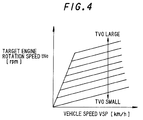
- a step S7 reference is made to a map shown in Fig. 4 to compute a target engine rotation speed tN e from the current vehicle speed VSP and throttle opening TVO .
- step S8 the vehicle speed VSP is multiplied by the constant K s to compute the output shaft rotation speed N sec of the CVT 29.
- the routine proceeds to a step S9 where the target engine rotation speed tN e is divided by the output shaft rotation speed N sec of the CVT 29 to compute the target speed ratio i p0 of the CVT 29.
- the routine proceeds to a step S10 where a speed ratio deviation e ip between the target speed ratio i p0 and the immediately preceding value i pt-1 of the command speed ratio is computed.
- the routine proceeds to a step S11 where the target speed ratio i p0 and real speed ratio i pr are compared. If the target speed ratio i p0 is less than the real speed ratio i pr , it is determined that an upshift is performed, and the routine proceeds to a step S12. If the target speed ratio i p0 equal to or larger than the real speed ratio i pr , it is determined that an upshift is not performed, and the routine proceeds to a step S13.
- a time constant ⁇ 0 is set to determine the dynamic characteristics of the command speed ratio i pt in a downshift.
- a small time constant ⁇ 2 is input to the time constant ⁇ 0 .
- a control flag F is set to "0".
- the time constant ⁇ 2 set on this occasion is stored as the immediately preceding value ⁇ -1
- the present value TVO of the throttle opening is stored as the immediately preceding value TVO -1 in the memory 310c, and the routine proceeds to a step S15.
- a deviation between the present value TVO of the throttle opening and the value TVO -1 on the immediately preceding occasion is compared with a threshold value ⁇ TVO .
- ⁇ TVO a threshold value
- the deviation of throttle opening is larger than the threshold value ⁇ TVO , it is determined that the opening variation of the throttle valve 19 is large and the routine proceeds to a step S16.
- the deviation of throttle opening is less than the threshold value ⁇ TVO , it is determined that the opening variation of the throttle valve 19 is small, and the routine proceeds to a step S17.
- the routine proceeds from the step S12 to the step S16 when the throttle opening TVO varies in the closing direction due to the driver releasing his foot from or returning it to the accelerator pedal, and an upshift is performed due to the decrease of throttle opening.
- the deviation between the present value i p0 of the target speed ratio and the value i p0-1 on the immediately preceding occasion is compared with a threshold value ⁇ i p0 .
- a threshold value ⁇ i p0 it is determined that an upshift is being performed wherein the opening of the throttle valve 19 is maintained substantially constant and the target speed ratio i p0 gradually varies with increase of vehicle speed VSP , and the routine proceeds to a step S18.
- the deviation of target speed ratio is larger than the threshold value ⁇ i p0 , the routine proceeds to the step S16.
- the time constant ⁇ 0 is set to determine the dynamic characteristic of the command speed ratio i pt which makes the real speed ratio i pr coincide with the present value i p0 of the target speed ratio during auto upshift. In order to increase the speed change response in auto upshift, this time constant ⁇ 0 is set to a small value ⁇ 1 .
- the routine then proceeds to a step S19, the control flag F is set to "0", the time constant ⁇ 1 which was set on the present occasion is stored as an immediately preceding value ⁇ -1 , the present value TVO of the throttle opening is stored as an immediately preceding value TVO -1 in the memory 310c, and the routine proceeds to the step S15.
- the command speed ratio i pt having a first order delay relative to the target speed ratio i p0 is computed by equation (1) from the target speed ratio i p0 and time constant ⁇ 0 .
- a step S20 the present value i p0 of the target speed ratio is stored as the immediately preceding value i p0-1 , and the input shaft rotation speed N pri is stored as an immediately preceding value N pri-1 in the memory 310c.
- step S21 the pulse control signal S s/m is computed according to the command speed ratio i pt which was computed in the step S15, and in a step S22, the pulse control signal S s/m is output to the drive circuit 311.
- step S30 it is determined whether or not the control flag F is "0".
- the routine proceeds to a step S32, and when it is not "0" the routine proceeds to a step S48.
- step S32 it is determined whether or not the present value TVO of the throttle opening is "0".
- the routine proceeds to a step S34, and when it is not "0" the routine proceeds to a step S36.
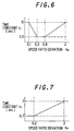
- a time constant ⁇ n according to the speed ratio deviation e ip is computed referring to a map shown in Fig. 6, and the routine proceeds to a step S38.
- the time constant ⁇ n computed referring to the map of Fig. 6 is larger than the time constant ⁇ 1 in auto upshift and the time constant ⁇ 2 in downshift.
- the time constant ⁇ n according to the speed ratio deviation e ip is computed referring to a map shown in Fig. 7, and the routine proceeds to the step S38.
- the time constant ⁇ n computed referring to the map of Fig. 7 is larger than the time constant ⁇ 1 in auto upshift and the time constant ⁇ 2 in downshift, but smaller than the time constant ⁇ n set in the step S34.
- step S38 it is determined whether or not the throttle valve 19 before a foot release operation or a foot return operation is nearly full open.
- step S42 the time constant ⁇ n computed in the step S34 or step S36 is stored as the time constant ⁇ 0 for computing the command speed ratio i pt and as the immediately preceding value ⁇ -1 of the time constant, and the routine proceeds to the step S15 of Fig. 3.
- step S40 it is determined whether or not the rotation speed of the engine 10 is high.
- the routine proceeds to a step S44, and when it is smaller than the threshold value N th , the routine proceeds to a step S42.
- a control counter CNT is set to a predetermined value CNT max , and the routine proceeds to a step S46.
- step S46 the control flag F is set to" 1" and the routine proceeds to a step S50.
- step S50 the control counter CNT is reduced, and the routine proceeds to a step S52.
- step S52 it is determined whether or not the control counter CNT is "0" or less.
- the routine proceeds to a step S54, and when the control counter CNT exceeds "0", the routine proceeds to a step S56.
- the present value ⁇ n of the time constant computed in the step S34 or step S36 is compared with the immediately preceding value ⁇ -1 .
- the routine proceeds to a step S58.
- the routine proceeds to a step S60.
- step S60 the control flag F is set to "2", and the routine proceeds to the step S42.
- a time constant ⁇ b which is smaller than ⁇ n and of which the variation amount from the immediately preceding value ⁇ -1 of the time constant is limited, is computed by the following equation (2).
- ⁇ b ⁇ lim ⁇ T + ⁇ -1
- a step S62 the time constant ⁇ b is stored as the time constant ⁇ 0 for computing the command speed ratio i pt , and as the immediately preceding value ⁇ -1 of the time constant, and the routine proceeds to the step S15 of Fig. 3.
- ⁇ n is set to the time constant ⁇ 0 and the speed change response falls to a low level. The driver therefore also does not suffer an acceleration shock.
- Fig. 9 is an enlargement of a part of Fig. 8 shown with by a circle marked A.
- ⁇ n which is larger than the ⁇ b is set to the time constant ⁇ 0 , and the command speed ratio i pt is computed. Due to this, the command speed ratio i pt follows a gradual slope and the speed change response gradually falls, so an acceleration shock is not given to the driver.
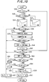
- Fig. 10 shows a second embodiment of this invention.
- This flowchart is executed by the CVT control unit 300 instead of the flowchart shown in Fig. 5.
- the step S40 of Fig. 5 is omitted, and steps S70, S72, and S74 are added between the steps S38 and S44.
- an input shaft rotation speed change rate ⁇ N pri is computed from a deviation between the present value N pri of the input shaft rotation speed and the value N pri-1 on the immediately preceding occasion.
- the input shaft rotation speed change rate ⁇ N pri is computed by the following equation (3).
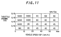
- ⁇ N pri (N pri - N pri-1 )/ ⁇ T opening TVO and vehicle speed VSP by referring to a map in Fig. 11. For example, if the present throttle opening TVO is 5/8 and the vehicle speed VSP is 40 km/h, the control value M n is 80 rpm/sec.
- the control value M n is set to increase with increases in the throttle opening TVO , and to increase with decreases in the vehicle speed VSP .
- step S74 the input shaft rotation speed change rate ⁇ N pri and the control value M n are compared, and if the change rate ⁇ N pri is equal to or less than the control value M n , the routine proceeds to the step S44, otherwise if the change rate ⁇ N pri exceeds the control value M n , the routine proceeds to the step S42.
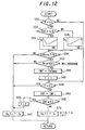
- Fig. 12 shows a third embodiment of this invention.
- This flowchart is executed by the CVT control unit 300 instead of the flowchart shown in Fig. 5.
- the steps S54, S58, S60, S62 of Fig. 5 are omitted, and a step S76 is added after the step S52.
- a time constant ⁇ c is set which is larger than the time constant ⁇ 1 for auto upshift and the time constant ⁇ 2 for downshift in Fig. 3, but smaller than the time constant ⁇ n which is set in the step S34 or the step S36 of Fig. 12.
- step S56 the control flag F is set to "2", and the routine proceeds to a step S42. Subsequently, the command speed ratio i pt is computed using the time constant ⁇ n which is larger value than ⁇ c .
- ⁇ c which is smaller than ⁇ n is set to the time constant ⁇ 0 immediately after upshift due to decrease of throttle opening starts, and the speed change response increases so that deceleration shock is suppressed.
- ⁇ n is set to the time constant ⁇ 0 and the speed change response falls, so the driver also does not experience an acceleration shock or the like.
- the time constant ⁇ 0 immediately after speed change begins is set to ⁇ b or ⁇ c which are smaller than ⁇ n so that the speed change response increases, and subsequently, the time constant ⁇ 0 is set to ⁇ n which is larger than ⁇ b or ⁇ c so that the speed change response falls.
- the CVT control unit 300 comprises the microcomputer 310, but an assembly of electronic circuits such as computing circuits may be used instead.
Landscapes
- Engineering & Computer Science (AREA)
- General Engineering & Computer Science (AREA)
- Mechanical Engineering (AREA)
- Control Of Transmission Device (AREA)
Applications Claiming Priority (3)
| Application Number | Priority Date | Filing Date | Title |
|---|---|---|---|
| JP21781797 | 1997-08-12 | ||
| JP21781797A JP3152176B2 (ja) | 1997-08-12 | 1997-08-12 | 無段変速機の変速制御装置 |
| JP217817/97 | 1997-08-12 |
Publications (3)
| Publication Number | Publication Date |
|---|---|
| EP0902216A2 true EP0902216A2 (fr) | 1999-03-17 |
| EP0902216A3 EP0902216A3 (fr) | 2001-02-28 |
| EP0902216B1 EP0902216B1 (fr) | 2003-10-29 |
Family
ID=16710214
Family Applications (1)
| Application Number | Title | Priority Date | Filing Date |
|---|---|---|---|
| EP98115017A Expired - Lifetime EP0902216B1 (fr) | 1997-08-12 | 1998-08-10 | Dispositif de commande pour transmission à variation continue |
Country Status (4)
| Country | Link |
|---|---|
| US (1) | US6138070A (fr) |
| EP (1) | EP0902216B1 (fr) |
| JP (1) | JP3152176B2 (fr) |
| DE (1) | DE69819272T2 (fr) |
Families Citing this family (10)
| Publication number | Priority date | Publication date | Assignee | Title |
|---|---|---|---|---|
| KR100373027B1 (ko) * | 2000-11-06 | 2003-02-25 | 현대자동차주식회사 | 무단 변속기의 변속비 제어방법 |
| JP4200952B2 (ja) * | 2004-08-09 | 2008-12-24 | トヨタ自動車株式会社 | 無段変速機を備えた車両の制御装置 |
| JP4561412B2 (ja) * | 2005-03-04 | 2010-10-13 | トヨタ自動車株式会社 | ベルト式無段変速機の変速制御装置 |
| JP4690255B2 (ja) * | 2006-06-15 | 2011-06-01 | トヨタ自動車株式会社 | ベルト式無段変速機の制御装置 |
| JP5087380B2 (ja) * | 2007-12-04 | 2012-12-05 | 日産自動車株式会社 | 無段変速機の変速制御装置 |
| DE102007058954A1 (de) * | 2007-12-07 | 2009-06-10 | Rolls-Royce Deutschland Ltd & Co Kg | Gasturbinenölversorgungssystem sowie Verfahren zum Betrieb einer Gasturbinen-Lager-Ölversorgung |
| JP5186938B2 (ja) * | 2008-02-05 | 2013-04-24 | トヨタ自動車株式会社 | 無段変速機の制御装置 |
| JP4911156B2 (ja) * | 2008-10-16 | 2012-04-04 | トヨタ自動車株式会社 | 無段変速機の制御装置 |
| JP5610193B2 (ja) | 2010-03-31 | 2014-10-22 | アイシン・エィ・ダブリュ株式会社 | 車両用変速装置 |
| CN114008355B (zh) * | 2019-06-20 | 2022-10-04 | 加特可株式会社 | 自动变速装置的控制装置及自动变速装置的控制方法 |
Citations (1)
| Publication number | Priority date | Publication date | Assignee | Title |
|---|---|---|---|---|
| US5695428A (en) | 1994-09-05 | 1997-12-09 | Unisia Jecs Corporation | Method and apparatus for controlling a continuously variable transmission |
Family Cites Families (4)
| Publication number | Priority date | Publication date | Assignee | Title |
|---|---|---|---|---|
| JPS6088259A (ja) * | 1983-10-19 | 1985-05-18 | Toyota Motor Corp | 車両用無段変速機の制御方法 |
| US5233523A (en) * | 1990-12-21 | 1993-08-03 | Ford Motor Company | Compensation for delay of scheduled gearshifts in automatic transmissions |
| US5383812A (en) * | 1993-03-08 | 1995-01-24 | Ford Motor Company | Radio control valve for a continuously variable transmission |
| JP3374677B2 (ja) * | 1996-10-31 | 2003-02-10 | 日産自動車株式会社 | 無段変速機の変速制御装置 |
-
1997
- 1997-08-12 JP JP21781797A patent/JP3152176B2/ja not_active Expired - Fee Related
-
1998
- 1998-08-10 DE DE69819272T patent/DE69819272T2/de not_active Expired - Fee Related
- 1998-08-10 EP EP98115017A patent/EP0902216B1/fr not_active Expired - Lifetime
- 1998-08-12 US US09/132,767 patent/US6138070A/en not_active Expired - Fee Related
Patent Citations (1)
| Publication number | Priority date | Publication date | Assignee | Title |
|---|---|---|---|---|
| US5695428A (en) | 1994-09-05 | 1997-12-09 | Unisia Jecs Corporation | Method and apparatus for controlling a continuously variable transmission |
Also Published As
| Publication number | Publication date |
|---|---|
| DE69819272D1 (de) | 2003-12-04 |
| DE69819272T2 (de) | 2004-05-13 |
| JPH1163193A (ja) | 1999-03-05 |
| JP3152176B2 (ja) | 2001-04-03 |
| US6138070A (en) | 2000-10-24 |
| EP0902216A3 (fr) | 2001-02-28 |
| EP0902216B1 (fr) | 2003-10-29 |
Similar Documents
| Publication | Publication Date | Title |
|---|---|---|
| EP0231059B1 (fr) | Système de commande pour un variateur continu de vitesse | |
| US5056637A (en) | System for controlling speed of an engine for a motor vehicle having a continuously variable transmission | |
| US5095776A (en) | System for controlling a continuously variable transmission having a torque converter | |
| EP0213852B1 (fr) | Commande de la pression d'huile d'une transmission variable d'une manière continue | |
| US4843918A (en) | System for controlling a continuously variable transmission having a torque converter | |
| EP0257960B1 (fr) | Système de commande pour un variateur continu de vitesse | |
| US6030313A (en) | Control system for continuously variable transmission | |
| US4730522A (en) | System for controlling the pressure of oil in a system for a continuously variable transmission | |
| US5012910A (en) | Transmission ratio control system for a continuously variable transmission | |
| US6138070A (en) | Controller for a continuously variable transmission | |
| US4781655A (en) | System for controlling the pressure of oil in a system for a continuously variable transmission | |
| EP0233781B1 (fr) | Commande des rappos de changement de vitesse d'une transmission continue | |
| EP0239365A2 (fr) | Commande du rapport d'une transmission continue | |
| JP3211737B2 (ja) | 無段変速機の変速比制御装置 | |
| EP0221668A1 (fr) | Système de contrôle d'une transmission à réglage en continu | |
| EP0207603B1 (fr) | Système de commande pour une transmission continue | |
| EP0896895B1 (fr) | Système anti-patinage pour véicules avec installation de freinage à antiblocage | |
| EP0205257B1 (fr) | Commande de la pression hydraulique pour une transmission à variation continue | |
| EP0217606B1 (fr) | Système de commande pour un variateur continu de vitesse | |
| JP3453986B2 (ja) | 無段自動変速機の変速制御装置 | |
| JPH1163194A (ja) | 無段変速機の変速制御装置 | |
| JP3505839B2 (ja) | 無段変速機の制御装置 | |
| JP2897584B2 (ja) | 無段変速機の制御装置 | |
| JP2529664B2 (ja) | 変速機の変速制御装置 | |
| EP0430632B1 (fr) | Transmission continue variable de vitesse avec convertisseur de couple |
Legal Events
| Date | Code | Title | Description |
|---|---|---|---|
| PUAI | Public reference made under article 153(3) epc to a published international application that has entered the european phase |
Free format text: ORIGINAL CODE: 0009012 |
|
| 17P | Request for examination filed |
Effective date: 19980810 |
|
| AK | Designated contracting states |
Kind code of ref document: A2 Designated state(s): DE FR GB |
|
| AX | Request for extension of the european patent |
Free format text: AL;LT;LV;MK;RO;SI |
|
| PUAL | Search report despatched |
Free format text: ORIGINAL CODE: 0009013 |
|
| AK | Designated contracting states |
Kind code of ref document: A3 Designated state(s): AT BE CH CY DE DK ES FI FR GB GR IE IT LI LU MC NL PT SE |
|
| AX | Request for extension of the european patent |
Free format text: AL;LT;LV;MK;RO;SI |
|
| AKX | Designation fees paid |
Free format text: DE FR GB |
|
| 17Q | First examination report despatched |
Effective date: 20020902 |
|
| GRAH | Despatch of communication of intention to grant a patent |
Free format text: ORIGINAL CODE: EPIDOS IGRA |
|
| GRAS | Grant fee paid |
Free format text: ORIGINAL CODE: EPIDOSNIGR3 |
|
| GRAA | (expected) grant |
Free format text: ORIGINAL CODE: 0009210 |
|
| AK | Designated contracting states |
Kind code of ref document: B1 Designated state(s): DE FR GB |
|
| REG | Reference to a national code |
Ref country code: GB Ref legal event code: FG4D |
|
| REF | Corresponds to: |
Ref document number: 69819272 Country of ref document: DE Date of ref document: 20031204 Kind code of ref document: P |
|
| ET | Fr: translation filed | ||
| PLBE | No opposition filed within time limit |
Free format text: ORIGINAL CODE: 0009261 |
|
| STAA | Information on the status of an ep patent application or granted ep patent |
Free format text: STATUS: NO OPPOSITION FILED WITHIN TIME LIMIT |
|
| 26N | No opposition filed |
Effective date: 20040730 |
|
| PGFP | Annual fee paid to national office [announced via postgrant information from national office to epo] |
Ref country code: DE Payment date: 20080821 Year of fee payment: 11 |
|
| PGFP | Annual fee paid to national office [announced via postgrant information from national office to epo] |
Ref country code: FR Payment date: 20080818 Year of fee payment: 11 |
|
| PGFP | Annual fee paid to national office [announced via postgrant information from national office to epo] |
Ref country code: GB Payment date: 20080820 Year of fee payment: 11 |
|
| GBPC | Gb: european patent ceased through non-payment of renewal fee |
Effective date: 20090810 |
|
| REG | Reference to a national code |
Ref country code: FR Ref legal event code: ST Effective date: 20100430 |
|
| PG25 | Lapsed in a contracting state [announced via postgrant information from national office to epo] |
Ref country code: FR Free format text: LAPSE BECAUSE OF NON-PAYMENT OF DUE FEES Effective date: 20090831 Ref country code: DE Free format text: LAPSE BECAUSE OF NON-PAYMENT OF DUE FEES Effective date: 20100302 |
|
| PG25 | Lapsed in a contracting state [announced via postgrant information from national office to epo] |
Ref country code: GB Free format text: LAPSE BECAUSE OF NON-PAYMENT OF DUE FEES Effective date: 20090810 |