EP0902211A2 - Hydraulischer Stossdämpfer - Google Patents
Hydraulischer Stossdämpfer Download PDFInfo
- Publication number
- EP0902211A2 EP0902211A2 EP98113231A EP98113231A EP0902211A2 EP 0902211 A2 EP0902211 A2 EP 0902211A2 EP 98113231 A EP98113231 A EP 98113231A EP 98113231 A EP98113231 A EP 98113231A EP 0902211 A2 EP0902211 A2 EP 0902211A2
- Authority
- EP
- European Patent Office
- Prior art keywords
- cylinder
- gas chamber
- shock absorber
- hydraulic shock
- piston
- Prior art date
- Legal status (The legal status is an assumption and is not a legal conclusion. Google has not performed a legal analysis and makes no representation as to the accuracy of the status listed.)
- Granted
Links
Images

Classifications
-
- B—PERFORMING OPERATIONS; TRANSPORTING
- B60—VEHICLES IN GENERAL
- B60G—VEHICLE SUSPENSION ARRANGEMENTS
- B60G13/00—Resilient suspensions characterised by arrangement, location or type of vibration dampers
- B60G13/001—Arrangements for attachment of dampers
- B60G13/005—Arrangements for attachment of dampers characterised by the mounting on the axle or suspension arm of the damper unit
- B60G13/008—Arrangements for attachment of dampers characterised by the mounting on the axle or suspension arm of the damper unit involving use of an auxiliary cylinder
-
- B—PERFORMING OPERATIONS; TRANSPORTING
- B60—VEHICLES IN GENERAL
- B60G—VEHICLE SUSPENSION ARRANGEMENTS
- B60G15/00—Resilient suspensions characterised by arrangement, location or type of combined spring and vibration damper, e.g. telescopic type
- B60G15/08—Resilient suspensions characterised by arrangement, location or type of combined spring and vibration damper, e.g. telescopic type having fluid spring
- B60G15/12—Resilient suspensions characterised by arrangement, location or type of combined spring and vibration damper, e.g. telescopic type having fluid spring and fluid damper
-
- F—MECHANICAL ENGINEERING; LIGHTING; HEATING; WEAPONS; BLASTING
- F16—ENGINEERING ELEMENTS AND UNITS; GENERAL MEASURES FOR PRODUCING AND MAINTAINING EFFECTIVE FUNCTIONING OF MACHINES OR INSTALLATIONS; THERMAL INSULATION IN GENERAL
- F16F—SPRINGS; SHOCK-ABSORBERS; MEANS FOR DAMPING VIBRATION
- F16F9/00—Springs, vibration-dampers, shock-absorbers, or similarly-constructed movement-dampers using a fluid or the equivalent as damping medium
- F16F9/06—Springs, vibration-dampers, shock-absorbers, or similarly-constructed movement-dampers using a fluid or the equivalent as damping medium using both gas and liquid
- F16F9/066—Units characterised by the partition, baffle or like element
- F16F9/067—Partitions of the piston type, e.g. sliding pistons
-
- F—MECHANICAL ENGINEERING; LIGHTING; HEATING; WEAPONS; BLASTING
- F16—ENGINEERING ELEMENTS AND UNITS; GENERAL MEASURES FOR PRODUCING AND MAINTAINING EFFECTIVE FUNCTIONING OF MACHINES OR INSTALLATIONS; THERMAL INSULATION IN GENERAL
- F16F—SPRINGS; SHOCK-ABSORBERS; MEANS FOR DAMPING VIBRATION
- F16F9/00—Springs, vibration-dampers, shock-absorbers, or similarly-constructed movement-dampers using a fluid or the equivalent as damping medium
- F16F9/32—Details
- F16F9/3207—Constructional features
- F16F9/3235—Constructional features of cylinders
-
- F—MECHANICAL ENGINEERING; LIGHTING; HEATING; WEAPONS; BLASTING
- F16—ENGINEERING ELEMENTS AND UNITS; GENERAL MEASURES FOR PRODUCING AND MAINTAINING EFFECTIVE FUNCTIONING OF MACHINES OR INSTALLATIONS; THERMAL INSULATION IN GENERAL
- F16F—SPRINGS; SHOCK-ABSORBERS; MEANS FOR DAMPING VIBRATION
- F16F9/00—Springs, vibration-dampers, shock-absorbers, or similarly-constructed movement-dampers using a fluid or the equivalent as damping medium
- F16F9/32—Details
- F16F9/48—Arrangements for providing different damping effects at different parts of the stroke
- F16F9/49—Stops limiting fluid passage, e.g. hydraulic stops or elastomeric elements inside the cylinder which contribute to changes in fluid damping
-
- B—PERFORMING OPERATIONS; TRANSPORTING
- B60—VEHICLES IN GENERAL
- B60G—VEHICLE SUSPENSION ARRANGEMENTS
- B60G2200/00—Indexing codes relating to suspension types
- B60G2200/10—Independent suspensions
- B60G2200/14—Independent suspensions with lateral arms
- B60G2200/142—Independent suspensions with lateral arms with a single lateral arm, e.g. MacPherson type
-
- B—PERFORMING OPERATIONS; TRANSPORTING
- B60—VEHICLES IN GENERAL
- B60G—VEHICLE SUSPENSION ARRANGEMENTS
- B60G2202/00—Indexing codes relating to the type of spring, damper or actuator
- B60G2202/10—Type of spring
- B60G2202/15—Fluid spring
- B60G2202/154—Fluid spring with an accumulator
-
- B—PERFORMING OPERATIONS; TRANSPORTING
- B60—VEHICLES IN GENERAL
- B60G—VEHICLE SUSPENSION ARRANGEMENTS
- B60G2202/00—Indexing codes relating to the type of spring, damper or actuator
- B60G2202/30—Spring/Damper and/or actuator Units
-
- B—PERFORMING OPERATIONS; TRANSPORTING
- B60—VEHICLES IN GENERAL
- B60G—VEHICLE SUSPENSION ARRANGEMENTS
- B60G2204/00—Indexing codes related to suspensions per se or to auxiliary parts
- B60G2204/10—Mounting of suspension elements
- B60G2204/12—Mounting of springs or dampers
- B60G2204/124—Mounting of coil springs
- B60G2204/1242—Mounting of coil springs on a damper, e.g. MacPerson strut
-
- B—PERFORMING OPERATIONS; TRANSPORTING
- B60—VEHICLES IN GENERAL
- B60G—VEHICLE SUSPENSION ARRANGEMENTS
- B60G2204/00—Indexing codes related to suspensions per se or to auxiliary parts
- B60G2204/10—Mounting of suspension elements
- B60G2204/12—Mounting of springs or dampers
- B60G2204/128—Damper mount on vehicle body or chassis
-
- B—PERFORMING OPERATIONS; TRANSPORTING
- B60—VEHICLES IN GENERAL
- B60G—VEHICLE SUSPENSION ARRANGEMENTS
- B60G2204/00—Indexing codes related to suspensions per se or to auxiliary parts
- B60G2204/10—Mounting of suspension elements
- B60G2204/12—Mounting of springs or dampers
- B60G2204/129—Damper mount on wheel suspension or knuckle
-
- B—PERFORMING OPERATIONS; TRANSPORTING
- B60—VEHICLES IN GENERAL
- B60G—VEHICLE SUSPENSION ARRANGEMENTS
- B60G2204/00—Indexing codes related to suspensions per se or to auxiliary parts
- B60G2204/40—Auxiliary suspension parts; Adjustment of suspensions
- B60G2204/43—Fittings, brackets or knuckles
- B60G2204/4304—Bracket for lower cylinder mount of McPherson strut
Definitions
- the present invention relates to a hydraulic shock absorber, which has an improved structure of a gas chamber defined by a partition wall member such as a free piston.
- the hydraulic shock absorber 1 has a cylinder 2 is filled with a hydraulic fluid, and a piston 3 is slidably provided therein.
- the piston 3 is provided with a damping valve 4 for generating a damping force, and is connected to one end of a piston rod 5.
- the cylinder 2 is fanned with a gas chamber 6, and a free piston 8 partitioning the gas chamber 6 and an oil chamber 7 is slidably provided in the cylinder 2.
- a surface roughness (coarseness) of the slidable range Y of the free piston 8 must be twice the degree as the surface roughness of the slidable rage X of the piston 3. For this reason, there is a problem of increasing the number of processes for machining the cylinder 2.
- the slidable range Y of the free piston 8 is set outside the slidable range X of the piston 3 ; for this reason, a stopper 9 for stopping a sliding motion of the free piston 8 must be feed in the cylinder 2. This increases the number of processes for machining the cylinder 2.
- a stud 2A for vehicle body attachment is fixed onto the cylinder 2 by bending the end portion of the cylinder 2.
- a lateral direction (direction perpendicular to a axis of the hydraulic shock absorber) load (torsion (twisting) load F) is applied (acts) onto the stud 2A, an insertion length of the stud 2A with respect to the cylinder 2 is short. For this reason, there is a need of increasing a strength of bending the stud 2A to the end portion of the cylinder 2 in order to secure a strength against the torsion load F.
- the present invention has been made in view of the aforesaid problems in the prior art. It is, therefore, an object of the present invention to provide a hydraulic shock absorber which can reduce the number of machining processes and the number of assembling processes.
- a hydraulic shock absorber comprises; a cylinder which is filled with a hydraulic fluid; a piston connected to one end of a piston rod, and which is slidably disposed in the cylinder; and a partition wall member which is slidably disposed in the cylinder so as to partition the cylinder into a gas chamber and an oil chamber, wherein a gas chamber cartridge inserted into one side of the cylinder so as to be fixed thereto, the partition wall member is slidably disposed in the gas chamber case of the gas chamber cartridge, defining one chamber partitioned by the partition wall member of the gas chamber case as the gas chamber encloses a gas therein, and defining the other chamber partitioned by the partition wall member of the gas chamber case as connected to the oil chamber on the other side of the cylinder.
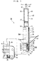
- a hydraulic shock absorber 10 which is used in a four-wheeled vehicle, is constructed integrally with a suspension spring (not shown) so as to constitute a cushion unit.
- This cushion unit is arranged on a vehicle body side and on a axle side.
- the suspension spring absorbs an impact from a road surface, and the hydraulic shock absorber 10 damps a vibration of the cushion unit, and thus, vibration of the vehicle body is restricted.
- Fig. 1 shows a the most extended state of the hydraulic shock absorber 10.
- the hydraulic shock absorber 10 is constructed in a manner that cylinder 12 comprises a single tube filled with a hydraulic fluid, and a piston 14 is slidably provided therein and is connected to one end of a piston rod 15.
- a gas chamber cartridge 48 which will be described later
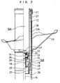
- a rod guide 18 Another end of the piston rod 15 penetrates through the rod guide 18 extend outside the cylinder 12.
- the cylinder 12 is partitioned into a rod-side chamber 16B which is filled with a hydraulic fluid and receives and houses the piston rod 15, and a piston-side chamber 16A which is filled with a hydraulic fluid and does not receive and house the piston rod 15.
- the rod guide 18 is provided adjacent to a seal 20, and this rod guide 18 is fixed on the cylinder 12 via the seal 20 in a state of being held between a stopper ring 19 and a retaining member 21.
- the retaining member 21 is supported on the cylinder 12 by means of a bending portion 29 on the other end portion of the cylinder 12.
- one end portion of the piston rod 15 penetrates through the center portion of the piston 14.
- a compression side channel 22 and an extension or expansion side channel (not shown) are alternately formed therethrough at the circumference of the piston rod 15.
- One side face of the piston 14 is provided with a compression side damping valve 24 for closing the compression side channel 22, and the other side face of the piston 14 is provided with an extension side damping valve 25 for closing the extension side channel.
- the piston 14, the compression side damping valve 24 and the extension side damping valve 25 are held down by means of valve retainers 26 and 30 and a nut 27, and are constructed integrally with the piston rod 15.
- the hydraulic fluid in the piston side chamber 16B passes through the extension side channel so as to elastically deform the extension side damping valve 25, and then, flows into the piston side chamber 16A. At this time, a extension side damping force is generated by a fluid resistance when the hydraulic fluid elastically deforms the extension side damping valve 25.
- a rebound rubber 28 is fitted into the piston rod 15 in a state of contact with the valve retainer 26.
- the rebound rubber 28 abuts the rod guide 18, the maximum stroke of the hydraulic shock absorber 10 is reached.
- an end member 34 is fastened onto the other end portion of the piston rod 15 by means of a nut 35, and a reinforcing tube 36 is fixed on the outer circumference of the end member 34.
- the reinforcing tube 36 has a cylindrical shape, and is attached with an upper guide bush 37 and a lower guide bush 38 at a predetermined distance at a inner peripheral surface on one side thereof. Further, the reinforcing tube 36 is slidably supported on a outer peripheral surface 12A of the cylinder 12 via the upper guide bush 37 and lower guide bush 38.
- an axle bracket 39 for supporting an axle is fixed to an outer circumferential portion on the other end side of the reinforcing tube 36 by welding.
- the hydraulic shock absorber 10 is an inverted strut type hydraulic shock absorber.
- the hydraulic shock absorber 10 supports the axle via the axle bracket 39 fixed to the reinforcing tube 36, and is supported on the vehicle body via a stud 49 (described later) of the gas chamber cartridge 48. Therefore, the reinforcing tube 36 functions as a strength member for receiving a load between the vehicle side and the axle side, together with the piston rod 15.
- a lower spring bracket 40 is welded to the outer peripheral portion on one side of the reinforcing tube 36.
- An upper spring bracket (not shown) is fixed to the stud 49.
- the suspension spring is stretched between the lower spring bracket 40 and the upper spring bracket.
- a spring load from the suspension spring is supported on the cylinder 12 via the stud 49, and further, is supported on the piston rod 15 via the end member 34.
- a reference numeral 41 denotes a seal member, and the seal member 41 is lubricated by oil filled between the cylinder 12 and the reinforcing tube 36.
- the hydraulic shock absorber 10 is formed with a gas chamber 45 in which a gas such as nitrogen gas is encapsulated, in order to compensate a capacity variation or rate caused when the piston rod 15 enters the cylinder 12 or retreats from the cylinder 12.
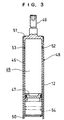
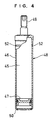
- the gas chamber 45 is constructed in the following manner. More specifically, the nitrogen gas is encapsulated in a gas chamber case 46, and a free piston 47, which functions as a partition wall member, is slidably provided in the gas chamber case 46, and thus, a gas chamber cartridge 48, which is a cartridge type, is inserted and fixed to one end side of the cylinder 12.
- the gas chamber 45 and the rod side chamber 16A are partitioned by means of the free piston 47.
- the gas chamber case 46 of the gas chamber cartridge 48 shown in Fig. 3 and Fig. 4 is formed by cold forging. More specifically, a metal mass placed on a die (not shown) and is extruded by means of punching (not shown) so as to form the gas chamber case. By doing so, a surface roughness on the inner peripheral surface of the case is produced at twice the surface roughness of the slidable range of the piston 14 in the cylinder 12. Further, by cold forging, the gas chamber case 46 is formed integrally with a stud 49 which is used as a fitting portion for attaching the hydraulic shock absorber to the vehicle body.
- the gas chamber cartridge 48 is constructed in the following manner. Nitrogen gas is encapsulated in the gas chamber case 46 thus formed with a predetermined gas pressure, and in this state, the free piston 47 pushed into the gas chamber case 46. Subsequently, an opening end portion of the gas chamber case 46 is bent inwardly so as to form a stopper 50 for preventing the free piston 47 from coming off. There is thus provided a gas chamber cartridge 48 which has a sealed structure encapsulating nitrogen gas, and is of a removable cartridge type.
- the gas chamber cartridge 48 thus constructed is inserted into one end side of the cylinder 12, that is, the end side where the piston rod 15 is not projected, and one end side of the cylinder 12 is bent inwardly, and thus, the gas chamber cartridge 48 is fixed to the cylinder 12 by a bending portion 51.
- an O ring 53 is fitted into a groove 52 formed in the overall outer circumference of the gas chamber case 46, and the gas chamber cartridge 48 and the cylinder 12 are mutually sealed by means of the O ring 53.
- the free piston 47 is prevented from coming off by the stopper 50, and is situated outside the slidable range of the piston 14 in the cylinder 12.
- the gas chamber cartridge 48 is inserted into one end side of the cylinder 12, and one end side of the cylinder 12 is bent inwardly, and thus, the gas chamber cartridge 48 is fixed to the cylinder 12 by the bending portion 51. At this time, the gas chamber cartridge 48 and one end side of the cylinder 12 are sealed by means of the O ring 53.
- the piston 14 connected to the piston rod 15 is inserted into the other end side of the cylinder 12, and the cylinder 12 is filled with a hydraulic fluid, and subsequently, the rod guide 18 and the seal 20 are inserted into the cylinder 12.
- the rod guide 18 and seal 20 are fixed to the cylinder 12 by means of the retaining member 21 supported on the stopper ring 19 and the bending portion 29, and then, the other end side of the cylinder 12 is sealed, and thus, a single-tube separation pressure type hydraulic shock absorber is constructed.
- the hydraulic shock absorber 10 of the aforesaid embodiment has the following effects 1 ⁇ to 4 ⁇ .
- the stopper 50 has been constructed by bending the opening end portion of the gas chamber case 46 of the gas chamber cartridge 48 so that the opening end portion thereof is bent inwardly. As shown by a chain double-dashed line in Fig. 3, a diameter of the inner peripheral surface of the opening end portion of the gas chamber cartridge 48 is reduced so as to form a reduced diameter portion 54. Then, the reduced diameter portion 54 may be used as a stopper for the free piston 47.
- the gas chamber cartridge 48 may be fixed to the cylinder 12 in a manner of forming a male screw on the outer periphery on one end side of the cylinder 12, and screwing a cap onto the male screw.
- the gas chamber cartridge 48 has been provided with the stud 49 for attaching the hydraulic shock absorber 10 to the vehicle body.
- An axle fitting portion having a bearing portion for supporting an axle is formed integrally with the gas chamber case 46 of the gas chamber cartridge 48, and thus, the hydraulic shock absorber 10 may be constructed as an erect strut type hydraulic shock absorber.
- the aforesaid hydraulic shock absorber 10 is a single tube type.
- the hydraulic shock absorber 10 may be a double tube type hydraulic shock absorber which is constructed in a manner that the gas chamber cartridge 48 is inserted into an inner tube, and an outer tube is provided outside the inner tube.
- a hydraulic shock absorber which can reduce the number of machining steps and the number of assembling steps.
Landscapes
- Engineering & Computer Science (AREA)
- General Engineering & Computer Science (AREA)
- Mechanical Engineering (AREA)
- Fluid-Damping Devices (AREA)
- Vehicle Body Suspensions (AREA)
Applications Claiming Priority (3)
| Application Number | Priority Date | Filing Date | Title |
|---|---|---|---|
| JP9259408A JPH1182590A (ja) | 1997-09-09 | 1997-09-09 | 油圧緩衝器 |
| JP259408/97 | 1997-09-09 | ||
| JP25940897 | 1997-09-09 |
Publications (3)
| Publication Number | Publication Date |
|---|---|
| EP0902211A2 true EP0902211A2 (de) | 1999-03-17 |
| EP0902211A3 EP0902211A3 (de) | 2001-07-11 |
| EP0902211B1 EP0902211B1 (de) | 2005-06-29 |
Family
ID=17333709
Family Applications (1)
| Application Number | Title | Priority Date | Filing Date |
|---|---|---|---|
| EP98113231A Expired - Lifetime EP0902211B1 (de) | 1997-09-09 | 1998-07-16 | Hydraulischer Stossdämpfer |
Country Status (4)
| Country | Link |
|---|---|
| US (1) | US6182806B1 (de) |
| EP (1) | EP0902211B1 (de) |
| JP (1) | JPH1182590A (de) |
| DE (1) | DE69830692T2 (de) |
Cited By (3)
| Publication number | Priority date | Publication date | Assignee | Title |
|---|---|---|---|---|
| GB2418001A (en) * | 2004-09-09 | 2006-03-15 | Tenneco Automotive Operating | A piston and cylinder strut assembly in which an end of the piston rod defines a contoured surface |
| CN104704258A (zh) * | 2012-10-08 | 2015-06-10 | 北京京西重工有限公司 | 具有气杯润滑剂腔的流体阻尼器组件 |
| DE102016014779A1 (de) * | 2016-12-10 | 2018-06-14 | Hydac Technology Gmbh | Hydropneumatische Kolbenzylinderanordnung |
Families Citing this family (9)
| Publication number | Priority date | Publication date | Assignee | Title |
|---|---|---|---|---|
| JP4100657B2 (ja) * | 2000-07-05 | 2008-06-11 | カヤバ工業株式会社 | 車高調整機能付きショックアブソーバのシール構造 |
| US6892865B2 (en) * | 2003-08-01 | 2005-05-17 | Arvin Technologies, Inc. | Monotube shock absorber remote reservoir fluid connection |
| US20050051397A1 (en) * | 2003-09-04 | 2005-03-10 | Brian Goscinski | Remote adjustable shock absorber |
| JP2008087592A (ja) * | 2006-09-29 | 2008-04-17 | Yokohama Rubber Co Ltd:The | 車体支持システム |
| KR101089574B1 (ko) * | 2009-08-18 | 2011-12-05 | 황의배 | 차량용 쇽업소버 |
| KR101479515B1 (ko) * | 2013-06-25 | 2015-01-07 | 주식회사 한국가스스프링 | 구리스 차단용 가스 실린더 |
| US9108484B2 (en) | 2013-07-25 | 2015-08-18 | Tenneco Automotive Operating Company Inc. | Recuperating passive and active suspension |
| US10434835B2 (en) | 2016-02-24 | 2019-10-08 | Tenneco Automotive Operating Company Inc. | Monotube active suspension system having different system layouts for controlling pump flow distribution |
| CN112211942B (zh) | 2019-11-04 | 2021-12-17 | 北京京西重工有限公司 | 支架、液压阻尼器组件及其之间的连接方法 |
Citations (1)
| Publication number | Priority date | Publication date | Assignee | Title |
|---|---|---|---|---|
| JPS51129988U (de) | 1975-03-24 | 1976-10-20 |
Family Cites Families (11)
| Publication number | Priority date | Publication date | Assignee | Title |
|---|---|---|---|---|
| DE2111967C3 (de) * | 1971-03-12 | 1974-11-28 | Peddinghaus Carl Ullrich Dr | Hydropneumatischer Schwingungsdämpfer |
| US3955655A (en) * | 1972-03-17 | 1976-05-11 | Rene Pornin | Adjustable liquid-operated shock-absorber |
| DE2223968A1 (de) * | 1972-05-17 | 1973-12-06 | Carl Ullrich Dr Peddinghaus | Hydropneumatischer schwingungsdaempfer |
| JPS51129988A (en) | 1975-05-06 | 1976-11-11 | Om Seisakusho:Kk | Lathe for machining crank shaft |
| AU553238B2 (en) * | 1983-09-26 | 1986-07-10 | Nhk Spring Co. Ltd. | Vehicle hydropneumatic suspension |
| FR2608242B1 (fr) * | 1986-12-12 | 1989-03-31 | Aerospatiale | Amortisseur-verin, contre-fiche le comportant, et train d'atterrissage equipe d'une telle contre-fiche |
| DE3840352A1 (de) * | 1988-11-30 | 1990-06-21 | Irmscher Gmbh | Einrohr-gasdruck-stossdaempfer |
| JPH03271014A (ja) * | 1990-03-20 | 1991-12-03 | Tokico Ltd | サスペンション装置 |
| DE4403127C2 (de) * | 1993-08-04 | 1998-01-22 | Mannesmann Sachs Ag | Pralldämpfer mit Deformationskörper |
| JPH08210412A (ja) * | 1995-02-06 | 1996-08-20 | Showa:Kk | 倒立型ストラットダンパ |
| US5797594A (en) * | 1995-07-22 | 1998-08-25 | Tokico, Ltd. | Hydraulic shock absorber |
-
1997
- 1997-09-09 JP JP9259408A patent/JPH1182590A/ja active Pending
-
1998
- 1998-07-16 EP EP98113231A patent/EP0902211B1/de not_active Expired - Lifetime
- 1998-07-16 DE DE69830692T patent/DE69830692T2/de not_active Expired - Fee Related
- 1998-08-12 US US09/132,832 patent/US6182806B1/en not_active Expired - Fee Related
Patent Citations (1)
| Publication number | Priority date | Publication date | Assignee | Title |
|---|---|---|---|---|
| JPS51129988U (de) | 1975-03-24 | 1976-10-20 |
Cited By (5)
| Publication number | Priority date | Publication date | Assignee | Title |
|---|---|---|---|---|
| GB2418001A (en) * | 2004-09-09 | 2006-03-15 | Tenneco Automotive Operating | A piston and cylinder strut assembly in which an end of the piston rod defines a contoured surface |
| CN104704258A (zh) * | 2012-10-08 | 2015-06-10 | 北京京西重工有限公司 | 具有气杯润滑剂腔的流体阻尼器组件 |
| US9353821B2 (en) | 2012-10-08 | 2016-05-31 | Beijingwest Industries Co., Ltd. | Fluid damper assembly with gas cup lubrication chamber |
| DE102016014779A1 (de) * | 2016-12-10 | 2018-06-14 | Hydac Technology Gmbh | Hydropneumatische Kolbenzylinderanordnung |
| US10962079B2 (en) | 2016-12-10 | 2021-03-30 | Hydac Technology Gmbh | Hydropneumatic piston-cylinder assembly |
Also Published As
| Publication number | Publication date |
|---|---|
| JPH1182590A (ja) | 1999-03-26 |
| EP0902211B1 (de) | 2005-06-29 |
| US6182806B1 (en) | 2001-02-06 |
| DE69830692D1 (de) | 2005-08-04 |
| EP0902211A3 (de) | 2001-07-11 |
| DE69830692T2 (de) | 2006-05-04 |
Similar Documents
| Publication | Publication Date | Title |
|---|---|---|
| US11181161B2 (en) | Shock absorber base valve assembly | |
| US3804217A (en) | Pressurized shock absorber | |
| US6182806B1 (en) | Hydraulic shock absorber | |
| EP0974476B1 (de) | Federsitzlagerungsstruktur für hydraulischen Dämpfer | |
| US6913127B2 (en) | Adjacent baffle design for shock absorber | |
| US20070051574A1 (en) | Rod guide seal | |
| CN111108302B (zh) | 前叉及前叉的制造方法 | |
| EP3196504A1 (de) | Stossdämpfer | |
| CN112539241A (zh) | 用于阻尼器的基座构件 | |
| US4966257A (en) | Shock absorbing or oscillation damper device | |
| JP2001180245A (ja) | 車両用懸架装置 | |
| JPH10238582A (ja) | 油圧緩衝器及び油圧緩衝器への作動油充填方法 | |
| US4331224A (en) | Hydraulic shock absorber for vehicles | |
| US4724938A (en) | Method of making and checking the jounce and rebound actions of an hydraulic damper | |
| JP3813782B2 (ja) | 車両用緩衝器の密封装置 | |
| JPH09217779A (ja) | 油圧緩衝器 | |
| US12558934B2 (en) | Damper oil seal cap with seal protection feature | |
| US20060042895A1 (en) | Base cup connection for shock absorber | |
| JP2000304082A (ja) | 油圧緩衝器 | |
| CN116368315B (zh) | 具有液压回弹止动器的减震器 | |
| JP2005076713A (ja) | 単筒式油圧緩衝器の支持部材取付構造 | |
| US6357734B1 (en) | Suspension damper with vehicle spring preload | |
| JP2005155793A (ja) | 油圧緩衝器 | |
| CN219472631U (zh) | 汽车减震器用帽构件以及汽车减震器 | |
| CN220248787U (zh) | 汽车减震器用帽构件以及汽车减震器 |
Legal Events
| Date | Code | Title | Description |
|---|---|---|---|
| PUAI | Public reference made under article 153(3) epc to a published international application that has entered the european phase |
Free format text: ORIGINAL CODE: 0009012 |
|
| AK | Designated contracting states |
Kind code of ref document: A2 Designated state(s): DE GB |
|
| AX | Request for extension of the european patent |
Free format text: AL;LT;LV;MK;RO;SI |
|
| PUAL | Search report despatched |
Free format text: ORIGINAL CODE: 0009013 |
|
| AK | Designated contracting states |
Kind code of ref document: A3 Designated state(s): AT BE CH CY DE DK ES FI FR GB GR IE IT LI LU MC NL PT SE |
|
| AX | Request for extension of the european patent |
Free format text: AL;LT;LV;MK;RO;SI |
|
| 17P | Request for examination filed |
Effective date: 20020110 |
|
| AKX | Designation fees paid |
Free format text: DE GB |
|
| 17Q | First examination report despatched |
Effective date: 20031107 |
|
| GRAP | Despatch of communication of intention to grant a patent |
Free format text: ORIGINAL CODE: EPIDOSNIGR1 |
|
| GRAS | Grant fee paid |
Free format text: ORIGINAL CODE: EPIDOSNIGR3 |
|
| GRAA | (expected) grant |
Free format text: ORIGINAL CODE: 0009210 |
|
| AK | Designated contracting states |
Kind code of ref document: B1 Designated state(s): DE GB |
|
| REG | Reference to a national code |
Ref country code: GB Ref legal event code: FG4D |
|
| REF | Corresponds to: |
Ref document number: 69830692 Country of ref document: DE Date of ref document: 20050804 Kind code of ref document: P |
|
| PLBE | No opposition filed within time limit |
Free format text: ORIGINAL CODE: 0009261 |
|
| STAA | Information on the status of an ep patent application or granted ep patent |
Free format text: STATUS: NO OPPOSITION FILED WITHIN TIME LIMIT |
|
| 26N | No opposition filed |
Effective date: 20060330 |
|
| PGFP | Annual fee paid to national office [announced via postgrant information from national office to epo] |
Ref country code: DE Payment date: 20070711 Year of fee payment: 10 |
|
| PGFP | Annual fee paid to national office [announced via postgrant information from national office to epo] |
Ref country code: GB Payment date: 20070710 Year of fee payment: 10 |
|
| GBPC | Gb: european patent ceased through non-payment of renewal fee |
Effective date: 20080716 |
|
| PG25 | Lapsed in a contracting state [announced via postgrant information from national office to epo] |
Ref country code: DE Free format text: LAPSE BECAUSE OF NON-PAYMENT OF DUE FEES Effective date: 20090203 |
|
| PG25 | Lapsed in a contracting state [announced via postgrant information from national office to epo] |
Ref country code: GB Free format text: LAPSE BECAUSE OF NON-PAYMENT OF DUE FEES Effective date: 20080716 |