EP0901201A1 - Elektrischer Steckverbinder mit vertragder Signalkompensation - Google Patents
Elektrischer Steckverbinder mit vertragder Signalkompensation Download PDFInfo
- Publication number
- EP0901201A1 EP0901201A1 EP98306772A EP98306772A EP0901201A1 EP 0901201 A1 EP0901201 A1 EP 0901201A1 EP 98306772 A EP98306772 A EP 98306772A EP 98306772 A EP98306772 A EP 98306772A EP 0901201 A1 EP0901201 A1 EP 0901201A1
- Authority
- EP
- European Patent Office
- Prior art keywords
- conductors
- connector
- crosstalk
- compensating
- signal
- Prior art date
- Legal status (The legal status is an assumption and is not a legal conclusion. Google has not performed a legal analysis and makes no representation as to the accuracy of the status listed.)
- Granted
Links
Images


Classifications
-
- H—ELECTRICITY
- H05—ELECTRIC TECHNIQUES NOT OTHERWISE PROVIDED FOR
- H05K—PRINTED CIRCUITS; CASINGS OR CONSTRUCTIONAL DETAILS OF ELECTRIC APPARATUS; MANUFACTURE OF ASSEMBLAGES OF ELECTRICAL COMPONENTS
- H05K1/00—Printed circuits
- H05K1/02—Details
- H05K1/0213—Electrical arrangements not otherwise provided for
- H05K1/0216—Reduction of cross-talk, noise or electromagnetic interference
- H05K1/0228—Compensation of cross-talk by a mutually correlated lay-out of printed circuit traces, e.g. for compensation of cross-talk in mounted connectors
-
- H—ELECTRICITY
- H01—ELECTRIC ELEMENTS
- H01R—ELECTRICALLY-CONDUCTIVE CONNECTIONS; STRUCTURAL ASSOCIATIONS OF A PLURALITY OF MUTUALLY-INSULATED ELECTRICAL CONNECTING ELEMENTS; COUPLING DEVICES; CURRENT COLLECTORS
- H01R13/00—Details of coupling devices of the kinds covered by groups H01R12/70 or H01R24/00 - H01R33/00
- H01R13/646—Details of coupling devices of the kinds covered by groups H01R12/70 or H01R24/00 - H01R33/00 specially adapted for high-frequency, e.g. structures providing an impedance match or phase match
- H01R13/6461—Means for preventing cross-talk
- H01R13/6464—Means for preventing cross-talk by adding capacitive elements
- H01R13/6466—Means for preventing cross-talk by adding capacitive elements on substrates, e.g. printed circuit boards [PCB]
-
- H—ELECTRICITY
- H01—ELECTRIC ELEMENTS
- H01R—ELECTRICALLY-CONDUCTIVE CONNECTIONS; STRUCTURAL ASSOCIATIONS OF A PLURALITY OF MUTUALLY-INSULATED ELECTRICAL CONNECTING ELEMENTS; COUPLING DEVICES; CURRENT COLLECTORS
- H01R13/00—Details of coupling devices of the kinds covered by groups H01R12/70 or H01R24/00 - H01R33/00
- H01R13/646—Details of coupling devices of the kinds covered by groups H01R12/70 or H01R24/00 - H01R33/00 specially adapted for high-frequency, e.g. structures providing an impedance match or phase match
- H01R13/6461—Means for preventing cross-talk
- H01R13/6467—Means for preventing cross-talk by cross-over of signal conductors
- H01R13/6469—Means for preventing cross-talk by cross-over of signal conductors on substrates
-
- H—ELECTRICITY
- H01—ELECTRIC ELEMENTS
- H01R—ELECTRICALLY-CONDUCTIVE CONNECTIONS; STRUCTURAL ASSOCIATIONS OF A PLURALITY OF MUTUALLY-INSULATED ELECTRICAL CONNECTING ELEMENTS; COUPLING DEVICES; CURRENT COLLECTORS
- H01R13/00—Details of coupling devices of the kinds covered by groups H01R12/70 or H01R24/00 - H01R33/00
- H01R13/646—Details of coupling devices of the kinds covered by groups H01R12/70 or H01R24/00 - H01R33/00 specially adapted for high-frequency, e.g. structures providing an impedance match or phase match
- H01R13/6473—Impedance matching
-
- H—ELECTRICITY
- H01—ELECTRIC ELEMENTS
- H01R—ELECTRICALLY-CONDUCTIVE CONNECTIONS; STRUCTURAL ASSOCIATIONS OF A PLURALITY OF MUTUALLY-INSULATED ELECTRICAL CONNECTING ELEMENTS; COUPLING DEVICES; CURRENT COLLECTORS
- H01R24/00—Two-part coupling devices, or either of their cooperating parts, characterised by their overall structure
- H01R24/60—Contacts spaced along planar side wall transverse to longitudinal axis of engagement
- H01R24/62—Sliding engagements with one side only, e.g. modular jack coupling devices
- H01R24/64—Sliding engagements with one side only, e.g. modular jack coupling devices for high frequency, e.g. RJ 45
-
- H—ELECTRICITY
- H05—ELECTRIC TECHNIQUES NOT OTHERWISE PROVIDED FOR
- H05K—PRINTED CIRCUITS; CASINGS OR CONSTRUCTIONAL DETAILS OF ELECTRIC APPARATUS; MANUFACTURE OF ASSEMBLAGES OF ELECTRICAL COMPONENTS
- H05K1/00—Printed circuits
- H05K1/02—Details
- H05K1/0213—Electrical arrangements not otherwise provided for
- H05K1/0216—Reduction of cross-talk, noise or electromagnetic interference
- H05K1/023—Reduction of cross-talk, noise or electromagnetic interference using auxiliary mounted passive components or auxiliary substances
- H05K1/0231—Capacitors or dielectric substances
-
- H—ELECTRICITY
- H05—ELECTRIC TECHNIQUES NOT OTHERWISE PROVIDED FOR
- H05K—PRINTED CIRCUITS; CASINGS OR CONSTRUCTIONAL DETAILS OF ELECTRIC APPARATUS; MANUFACTURE OF ASSEMBLAGES OF ELECTRICAL COMPONENTS
- H05K1/00—Printed circuits
- H05K1/16—Printed circuits incorporating printed electric components, e.g. printed resistor, capacitor, inductor
- H05K1/162—Printed circuits incorporating printed electric components, e.g. printed resistor, capacitor, inductor incorporating printed capacitors
-
- H—ELECTRICITY
- H05—ELECTRIC TECHNIQUES NOT OTHERWISE PROVIDED FOR
- H05K—PRINTED CIRCUITS; CASINGS OR CONSTRUCTIONAL DETAILS OF ELECTRIC APPARATUS; MANUFACTURE OF ASSEMBLAGES OF ELECTRICAL COMPONENTS
- H05K2201/00—Indexing scheme relating to printed circuits covered by H05K1/00
- H05K2201/09—Shape and layout
- H05K2201/09209—Shape and layout details of conductors
- H05K2201/09218—Conductive traces
- H05K2201/09245—Crossing layout
-
- H—ELECTRICITY
- H05—ELECTRIC TECHNIQUES NOT OTHERWISE PROVIDED FOR
- H05K—PRINTED CIRCUITS; CASINGS OR CONSTRUCTIONAL DETAILS OF ELECTRIC APPARATUS; MANUFACTURE OF ASSEMBLAGES OF ELECTRICAL COMPONENTS
- H05K2201/00—Indexing scheme relating to printed circuits covered by H05K1/00
- H05K2201/10—Details of components or other objects attached to or integrated in a printed circuit board
- H05K2201/10007—Types of components
- H05K2201/10189—Non-printed connector
-
- Y—GENERAL TAGGING OF NEW TECHNOLOGICAL DEVELOPMENTS; GENERAL TAGGING OF CROSS-SECTIONAL TECHNOLOGIES SPANNING OVER SEVERAL SECTIONS OF THE IPC; TECHNICAL SUBJECTS COVERED BY FORMER USPC CROSS-REFERENCE ART COLLECTIONS [XRACs] AND DIGESTS
- Y10—TECHNICAL SUBJECTS COVERED BY FORMER USPC
- Y10S—TECHNICAL SUBJECTS COVERED BY FORMER USPC CROSS-REFERENCE ART COLLECTIONS [XRACs] AND DIGESTS
- Y10S439/00—Electrical connectors
- Y10S439/941—Crosstalk suppression
Definitions
- This invention relates to an apparatus and method for reducing interference between conductors in an electrical connector by the introduction of compensating signals.
- wire-pair a pair of wires
- the transmitted signal comprises the voltage difference between the wires without regard to the absolute voltages present.
- Each wire in a wire-pair is capable of picking up electrical noise from sources such as lightning, automobile spark plugs and radio stations to name but a few.
- Balance is a measure of impedance symmetry in a wire pair as between its individual conductors and ground.
- return loss comprises a reflection of the incoming signal that effectively occurs when the terminating impedance does not match the source impedance.
- electrical noise that is picked up from nearby wires that may extend in the same general direction for long distances. This is referred to as crosstalk, and so long as the same noise signal is added to each wire in the wire-pair, then the voltage difference between the wires will remain about the same. In all of the above situations. undesirable signals are present on the electrical conductors that can interfere with the information signal.
- FIG. 1 discloses a high-speed communication terminal 1 and cables 2, 3 -- each containing several wire-pairs. Electrical interconnection between cables may be facilitated by the use of standard telecommunications connectors that are frequently referred to as modular plugs and jacks, or other style plugs and receptacles.
- Connecting apparatus includes a modular plug 20, and a modular jack 30 that comprises a jack frame 310 and a connector assembly 320. Modular plug 20 inserts into opening 315 on the front side of jack frame 310 and communicates electrical signals to and from terminal 1.
- a connector assembly 320 Inserted into the back side of jack frame 310 is a connector assembly 320, which receives and holds wires from cable 3 that are individually pressed into slots 321 where mechanical and electrical connection is made. And while there are many places in FIG. 1 where undesirable signals attributable to crosstalk, imbalance and return loss are present, it is particularly desirable to reduce the undesirable signals that arise within connecting apparatus 20, 30.
- Connecting apparatus 20, 30 may include up to eight or more wires that are close together -- a condition that leads to excessive crosstalk over relatively short distances. If the electrical conductors that interconnect with these terminals are close together for any distance, as is the case in present designs, then crosstalk between these wire-paths is particularly troublesome.
- near-end crosstalk (NEXT), which is the crosstalk energy traveling in the opposite direction to that of the signal in the disturbing wire-pair, is about 25 dB below the level of the incoming signal at 100 MHz in modular jack designs such as shown in U.S. Patent 5,096,442 that issued on March 17, 1992.
- One such modular jack is known as the M1 Communication Outlet, which is manufactured by Lucent Technologies.
- FIG. 2 illustrates the polarity and magnitude of the NEXT between two pairs of conductors within the plug 20 and jack 30 by positive (+) signs. Note that the overall NEXT in the connecting apparatus comes from both the plug 20 and jack 30. Because the conductor paths within the plug and jack are close together and extend in a straight line. NEXT is substantial.
- FIG. 3 illustrates the polarity and magnitude of the NEXT between two pairs of conductors within the plug 20 and jack 30 by positive (+) and negative (-) signs.
- This simple technique improves NEXT at 100 MHz, by a startling 17 dB, thereby enabling the electrical connector to comply with the Category 5 requirements specified in ANSI/EIA/TIA - 568A.
- An example of such a modular jack is the M100 Communication Outlet, which is manufactured by Lucent Technologies.
- offending crosstalk is shown in Section 0 coming from the plug 20 and a first portion of jack 30; while compensating crosstalk is shown in Section I coming from a second portion of jack 30.
- An electrical connector includes at least two conductors that extend along an interconnection path between input and output terminals of the connector.
- Undesirable signal coupling between the conductors is significantly reduced by recognizing that the undesired signal, A 0 , is a vector quantity whose magnitude and phase both need to be considered.
- Compensating signals A 1 , A 2 ,... A n are coupled between the conductors at two or more locations along the interconnection path in order to approximately cancel the undesired signal.
- the magnitude and phase of the compensating signals at the two or more locations are selected to substantially cancel the magnitude and phase of the undesired signal.
- the locations where compensating signals are introduced are time delayed with respect to each other in order to control the phase of the compensating signals so that the vector sum A 0 + A 1 +...+ A n approximately equals zero.
- the undesired signal comprises NEXT between pairs of conductors.
- the locations where compensating signals are introduced are separated in distance along the interconnection path to create the time delay.
- a printed wiring board having multiple layers is used in the construction of the connector. Such construction allows many stages of compensating signals to be introduced in a compact space.
- a metallic lead frame having multiple crossover stages is used in the construction of the connector.
- a printed wiring board having discrete components is used in the construction of the connector.
- time-delayed signal compensation according to the invention is useful for improving the return loss, balance and crosstalk characteristics of an electrical connector.
- crosstalk was originally coined to indicate the presence in a telephone receiver of unwanted speech sounds from another telephone conversation.
- crosstalk that is caused by signal coupling between adjacent circuits.
- the most common coupling is due to near-field effects and can usually be characterized by mutual inductance and direct capacitance. This can best be illustrated by considering two parallel balanced transmission paths.
- One circuit (the disturbing circuit) is a source of signal energy that is undesirably coupled into an adjacent circuit via stray capacitance and mutual inductance.
- Near-end crosstalk (NEXT) is crosstalk energy that travels in the opposite direction to that of the signal in the disturbing circuit
- far-end crosstalk is crosstalk energy that travels in the same direction as the signal in the disturbing circuit.
- Circuit analysis indicates that NEXT is frequency dependent and, for connecting hardware, its magnitude typically increases with frequency at a 6.0 dB per octave rate.
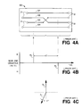
- FIGS. 4A-4C illustrate the prior-art compensation technique shown in FIG. 3 and disclosed in greater detail in the '647 patent.
- FIG. 4A shows that conductors 301-304 extend between input terminals 31 and output terminals 32 of connecting apparatus 300, which comprises metallic conductors supported by a dielectric structure.
- Conductors 302, 303 form one wire-pair whose electrical signals are coupled to wire pair 301, 304 because of their proximity.
- the crosstalk between these pairs is graphically shown in FIG. 4B along a time axis to illustrate the ultimate limitation of this prior-art compensation technique.
- the crosstalk, A 0 in Section 0 is a vector quantity that is referred to as the offending crosstalk. It includes crosstalk from modular plug 20 (see FIG.
- the offending crosstalk has a positive polarity. Compensation is achieved by crossing conductor 302 over the path of conductor 303 so that the polarity of the crosstalk between the conductor pairs is reversed. Accordingly. the crosstalk, A 1 in Section I is referred to as compensating crosstalk and it has a negative polarity. And although it is recognized that crosstalk is incrementally distributed along the interconnection path that extends between terminals 31 and terminals 32, for the purpose of analysis, A 0 and A 1 are lumped and effectively occur at the midpoints of Sections 0 and I as shown in FIG. 4B.
- Section -- a region where signal coupling exists, between conductors or a pair of conductors, along an interconnection path that extends between input and output terminals. In that region, the magnitude and phase of the signal coupling are substantially similar, without abrupt change. Also referred to as a stage.
- Effective location -- a particular location, usually the center, within a Section where distributed signal coupling is effectively lumped for the purpose of analysis, or where discrete signal coupling exists, between the conductors or the pair of conductors.
- FIG. 4C is a vector diagram that illustrates why offending crosstalk A 0 cannot be completely canceled by compensating crosstalk A 1 , whose overall phase includes 180 degrees (attributable to conductor crossover) plus a phase shift ⁇ (attributable to the round trip delay of ⁇ seconds). Indeed in the present situation. assuming that vectors A 0 and A 1 have the same magnitude, then the offending crosstalk A 0 can, at best, be improved by 17 dB at 100 MHz for a connector having the dimensions shown in FIG. 3.
- FIG. 5A schematically illustrates an improved technique for creating compensating crosstalk in an electrical connector according to the invention.
- FIG. 5A shows that conductors 501-504 extend between input terminals 51 and output terminals 52 of connecting apparatus 500.
- Conductors 501, 504 form one wire pair that straddles wire-pair 502, 503.
- Such straddling increases the amount of signal coupling between the wire pairs and represents a worst case situation.
- the present invention is equally applicable to the situation wherein conductors 501, 502 form one wire pair that is near wire-pair 503. 504.
- the crosstalk between the two pairs is graphically shown in FIG. 5B along a time axis.
- the crosstalk, A 0 , in Section 0 is a vector quantity that is referred to as the offending crosstalk. It includes crosstalk from modular plug 20 (see FIG. 3) and the input region of jack 30. For the purpose of analysis, the offending crosstalk has a positive polarity. Compensation is achieved by crossing conductor 502 over the path of conductor 503 so that the polarity of the crosstalk between the conductor pairs is reversed. Accordingly, the crosstalk, A 1 , in Section I is referred to as compensating crosstalk and it has a negative polarity.
- the present invention includes at least one more component of compensating crosstalk, which is designated A 2 and illustratively shown in FIG. 5B having the same approximate magnitude as the offending crosstalk A 0 .
- FIG. 12 is a graph of a calculated NEXT as a function of frequency for a connector having three (3) Sections of compensating crosstalk. Note that a null is positioned at about 180 MHz to reduce NEXT in the frequency range 100 - 200 MHz. However, FIG. 12
- NEXT is more than 49 dB below the level of the incoming signal at all frequencies below 200 MHz; and more than 55 dB below the level of the incoming signal at all frequencies below 100 MHz. And as more Sections of compensating crosstalk are added, then more complete vector cancellation is approached (i.e., cancellation occurs over a broader span of frequencies).
- compensating crosstalk may also be provided by a plug, which inserts into the communication jack. It is clear that plugs and jacks are intended to operate together, and that it is their combined crosstalk that is reduced approximately to zero by the present invention.
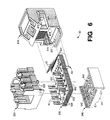
- FIG. 6 is an exploded perspective view of a first embodiment of an electrical connector having time-delayed crosstalk compensation according to the invention.
- the connector 60 comprises a printed wiring board assembly 630, which is enclosed within dielectric components 610, 620, 640.
- the assembly 630 includes a multi-layered printed wiring board 600 having conductive paths that extend between a jackwire terminal region 635 near a forward edge 631 of the board. and a wire-connection terminal region 634 near a rear edge 633 of the board.
- a number (e. g., eight) of spring jackwires 61 extend from the jackwire terminal region 635 at an acute angle relative to the top surface of the wiring board 600.
- the jackwires 61 connect at their bottom ends to corresponding conductive paths in the wiring board.
- the conductive paths are dimensioned and arranged on the board layers in such a manner that crosstalk is substantially reduced over an entire connection comprising electrical connector 60 and an associated plug (e. g., a modular plug 20 such as shown in FIG. 1).
- the board may also contain discrete components such as resistors, capacitors and inductors for crosstalk reduction between pairs of conductive paths.
- the bottom ends of the jackwires 61 are inserted in metal-plated openings in the bottom surface of the wiring board to connect with the conductive paths, and the jackwires wrap around a curvilinear forward end of a jackwire block 63.
- the bottom ends of the jackwires 61 have a "needle eye" construction that allows the ends to be pushed into the metal-plated openings underneath the board 600. These openings have a diameter that is slightly less than that of the bottom ends of the jackwires. A reliable electrical connection is therefore established between the jackwires and the conductive paths without a need for soldering.
- Insulation-displacement connector (IDC) terminals 62 are mounted at both rear sides of the wiring board 600 as shown in FIG. 6. Each of the terminals 62 connects to a corresponding conductive path associated with a different one of the spring jackwires 61. A pair of terminal housing mounting holes 632 are formed in the wiring board 600 along a center line between the rear sides of the board.
- IDC Insulation-displacement connector
- a jack frame 610 for the electrical connector 60 may be similar to one disclosed in co-pending U.S. Patent Application No. 08/866,796 entitled Multi-Position Jack Frame, filed May 30, 1997, and assigned to the assignee of the present invention. All relevant portions of the Application are incorporated by reference herein.
- a jack frame similar to the one disclosed in the above-mentioned U. S. Patent 5,096,442 may also be used for the jack frame 610.
- the frame 610 has an opening or cavity 615 that is dimensioned to receive a modular plug in its front end, and a rear opening or cavity 616 that is dimensioned to receive the forward edge 631 of the wiring board 600 including jackwires 61.
- the rear opening of the jack frame is formed with a number (e.g., eight) of vertical slots 618, which receive corresponding ones of the jackwires 61 and guide each jackwire to deflect when a plug (not shown) is inserted through the front opening 615 of the jack frame. Wire conductors carried by the inserted plug thus establish electrical contact with corresponding ones of the jackwires 61.
- An electrically insulative or dielectric terminal housing 620 is formed to protect and to permit wire lead access to the wire-connection terminal region 634 on top of wiring board 600.
- the housing 620 may also be formed of a plastics material that meets all applicable standards with respect to electrical insulation an flammability. Such plastics materials include, but are not limited to, Polyvinyl Chloride (PVC). Acrylonitrile Butadiene Styrene (ABS), or polycarbonate.
- PVC Polyvinyl Chloride
- ABS Acrylonitrile Butadiene Styrene
- the housing 620 has a pair of mounting posts 622 that project from a bottom surface of the housing. When the housing 620 is aligned with the IDC terminals 62 on the wiring board 600 and lowered to surround the terminals, the mounting posts 622 align with the mounting holes 632 in the board 600 and pass through them to project from below the board.
- a cover 640 is made from a material that may be the same or similar to that of the housing 620 and the jack frame 610. Cover 640 is formed to protect the bottom of the board 600 at the wire-connection terminal region 634.
- the cover includes a pair of openings 642 formed along a center line between sides of the cover 640, to align with tips of the housing mounting posts 622 that project below the wiring board 600.
- the wiring board 600 is "sandwiched" or captured between the housing 620 and the cover 640, and the tips of the mounting posts 622 are preferably joined to the body of the cover by, for example, an ultrasonic welding probe inserted into the cover openings 642 from below the cover.
- the tips of the mounting posts 622 and surrounding cover body melt and fuse with one another to form solid joints when cooled.
- the jack frame 610 has a latch 617 protruding below its rear opening 616.
- the cover 640 has a pair of shoulders 647 adjacent the front and back edges of the cover.
- wiring board 600 is disclosed in FIGS. 7A-7F.
- An end view of printed wiring board 600 is shown in FIG. 7A having eight layers of wiring paths for introducing compensating crosstalk according to the invention.
- Each of the layers comprises one or more metallic paths of thickness d 1 positioned on a dielectric material of thickness d 2 .
- d 1 0.04 millimeters (mm)
- d 2 0.30 mm.
- An exemplary construction is disclosed in U.S. Patent Application 08/668553, which was filed on June 21, 1996 by Choudhury et al. and assigned to the present assignee. The relevant portions of that Application are hereby incorporated by reference.
- Each printed wiring board comprises a board material, such as FR-4, with conductive paths patterned on its top and bottom surfaces by standard techniques such as photolithography. And while eight layers of conductor paths are shown in this illustrative embodiment, it will be appreciated that any number can be employed.
- FIGS. 7B-7F show top views of the wiring layouts on each of the layers of the printed wiring board 600. Note that the same wiring layout 603, shown in FIG. 7D, is used on four (4) layers of the wiring board.
- the wiring layout of FIGS. 7B-7F provides three stages of compensating crosstalk between wire-pair 1 (pins 4, 5) and wire-pair 2 (pins 3, 6), which are identified in FIG. 7B. (It is noted that the industry generally refers to pins 3, 6 as wire-pair 3; e.g., see FIG. 2 of the '647 patent) Reference is briefly made to FIG.
- FIGS. 9 and 10 show discrete capacitors 612 connected between wire-pair 1 and wire-pair 2 at the closest possible point to where signals enter layer 603 in the jackwire terminal region 635 of board 600, and they comprise the first stage of compensating crosstalk.
- these discrete capacitors 612 comprise closely spaced wiring patterns on a printed wiring board, stand-alone discrete component structures are shown in FIGS. 9 and 10.
- FIG. 8 is an exploded perspective view of a second embodiment of an electrical connector having time-delayed crosstalk compensation according to the invention.
- Electrical connector 80 comprises spring block 830, conductor array 800, cover 840 and jack frame 810.
- Conductor array 800 is made from two lead frames, one of which includes conductors 801, 803, and the other includes conductors 802, 804 which are identical to each other. These lead frames are reversed, left-to-right, with respect to each other and overlaid on each other in the manner disclosed in U. S. Patent 5,186,647. These lead frames are positioned on the top surface of spring block 830 which includes grooves having the same pattern as the overlaid lead frames.
- IDC terminals 823 are folded down the sides of the spring block while the conductors in Section 0 of conductor array 800 are wrapped around tongue-like projection 831 of the spring block 830. Thereafter, cover 840 is joined to the spring block to create a unitary structure.
- spring block 830, cover 840 and jack frame 810 are all made from a thermoplastic material such as PVC.
- conductor leads 802 and 803 cross over each other in two locations in order to provide two Sections (I and II) where compensating crosstalk is introduced in order to cancel the offending crosstalk in Section 0.
- FIG. 5A where the same crossover technology is employed on a printed wiring board to provide two stages of compensating crosstalk.
- FIG. 9 illustrates a connecting apparatus 90 that embodies the present invention in a convenient design.
- wire-pair 1 comprising conductors 902, 903 is straddled by wire-pair 2 comprising conductors 901, 904.
- These conductors all extend along a top surface of printed wiring board 900 without crossing over each other.
- offending crosstalk comes from closely spaced wires within a modular plug (not shown), modular jack 910, and conductors 901-904 on board 900.
- Discrete components 912 are used to couple electrical signals between wire-pairs 1 and 2 thereby introducing compensating crosstalk between the wire pairs. And while only two components 912 are shown, it is understood that they represent a combination of resistors and/or capacitors and/or inductors that are selected to provide compensating crosstalk, having a predetermined magnitude and phase at a given frequency, between wire-pairs 1 and 2 in Section I.
- a second stage (Section II) of compensating crosstalk is provided, and it includes the crosstalk coming from conductors 901-904 as well as the crosstalk coming from terminal block 920, which is used for making wire connections and preferably includes four IDC terminals.
- FIG. 1 Discrete components 912
- FIG. 9 only shows a single jack frame 910 and terminal block 920, but it is understood that it is common practice to install many jack frames and terminal blocks on a single board. Moreover, it is common practice to have more than four conductive paths between the jack frame and terminal block and such structures are contemplated by the present invention.
- FIG. 10 is a variation on the embodiment of FIG. 9 in which crossover technology is combined with discrete component technology to introduce multiple stages of compensating crosstalk according to the present invention.
- offending crosstalk comes from closely spaced wires within a modular plug (not shown), modular jack 910, and conductors on board 1000.
- This offending crosstalk is substantially canceled in magnitude and phase at a given frequency by compensating crosstalk from Sections I-III.
- crossover technology is illustratively used to introduce compensating crosstalk that is almost 180 degrees out of phase with the offending crosstalk.
- crossover technology is used again to introduce compensating crosstalk that is almost 180 degrees out of phase with the crosstalk introduced in Section I.
- additional compensating crosstalk is introduced via discrete components 1012 whose magnitude and phase at a given frequency are selected to substantially eliminate all NEXT in connecting apparatus 100.
- FIG. 11 is a vector diagram of crosstalk in a three-stage compensation scheme, according to the invention, for the electrical connector of FIG. 6.
- offending crosstalk vector A 0 is substantially canceled by compensating crosstalk vectors A 1 , A 2 , A 3 whose magnitudes and polarities are generally indicated in FIG. 11.
- the offending crosstalk A 0 is primarily attributable to the closely spaced parallel wires within the conventional modular plug 20 (see FIG. 1), which is inserted into the electrical connector 60 (see FIG. 6) of the present invention.
- the magnitudes of the vectors A 0 - A 3 are in millivolts (mv) of crosstalk per volt of input signal power.
- the effective separation between stages is designed to be about 0.4 nanoseconds.
- the following vector magnitudes apply to FIG. 11:
- vector magnitudes and phases provides a null at about 180 MHz in order to reduce NEXT to a level that is 60 dB below the level of the input signal for all frequencies below 100 MHz.
- vectors can be selected to produce one or more nulls at other frequencies in order to meet particular design objectives.
- FIG. 12 is a graph showing calculated NEXT as a function of frequency using the vector magnitudes discussed in connection with FIG. 11.
- the present invention represents the first recognition that delayed compensation stages can reduce NEXT to negligible values in practical electrical connectors.
Priority Applications (1)
| Application Number | Priority Date | Filing Date | Title |
|---|---|---|---|
| DK98306772T DK0901201T3 (da) | 1997-09-02 | 1998-08-25 | Elektrisk konnektor med tidsforsinket signalkompensering |
Applications Claiming Priority (2)
| Application Number | Priority Date | Filing Date | Title |
|---|---|---|---|
| US923741 | 1997-09-02 | ||
| US08/923,741 US5997358A (en) | 1997-09-02 | 1997-09-02 | Electrical connector having time-delayed signal compensation |
Publications (2)
| Publication Number | Publication Date |
|---|---|
| EP0901201A1 true EP0901201A1 (de) | 1999-03-10 |
| EP0901201B1 EP0901201B1 (de) | 2000-03-22 |
Family
ID=25449194
Family Applications (1)
| Application Number | Title | Priority Date | Filing Date |
|---|---|---|---|
| EP98306772A Expired - Lifetime EP0901201B1 (de) | 1997-09-02 | 1998-08-25 | Elektrischer Steckverbinder mit verschobener Signalkompensation |
Country Status (8)
| Country | Link |
|---|---|
| US (1) | US5997358A (de) |
| EP (1) | EP0901201B1 (de) |
| JP (1) | JP3356695B2 (de) |
| AU (1) | AU737453B2 (de) |
| CA (1) | CA2245377C (de) |
| DE (1) | DE69800099T2 (de) |
| DK (1) | DK0901201T3 (de) |
| GR (1) | GR3033726T3 (de) |
Cited By (52)
| Publication number | Priority date | Publication date | Assignee | Title |
|---|---|---|---|---|
| EP1041683A1 (de) * | 1999-04-01 | 2000-10-04 | INFRA + Société anonyme dite: | Niederspannungsteckverbinder |
| WO2001015283A1 (en) * | 1999-08-20 | 2001-03-01 | Adc Telecommunications, Inc. | Jack including crosstalk compensation for printed circuit board |
| EP1100163A1 (de) * | 1999-11-12 | 2001-05-16 | Berg Electronics Manufacturing B.V. | Elektrischer Steckverbinder mit geringem Übersprechen |
| EP1109268A1 (de) * | 1999-12-15 | 2001-06-20 | Avaya Technology Corp. | Modular Stecker mit Steckerpositionierungselement |
| WO2001080376A1 (en) * | 2000-04-14 | 2001-10-25 | Tyco Electronics Corporation | Electrical connector for reducing crosstalk |
| EP1069655A3 (de) * | 1999-07-14 | 2002-04-17 | Berg Electronics Manufacturing B.V. | Elektrischer Verbinder mit verringertem Nebensprechen |
| US6511344B2 (en) | 2001-07-02 | 2003-01-28 | Fci Americas Technology, Inc. | Double-deck electrical connector with cross-talk compensation |
| WO2003030308A1 (en) * | 2001-09-28 | 2003-04-10 | Itt Manufacturing Enterprises, Inc. | Electrical connector |
| EP1406354A2 (de) * | 2002-10-03 | 2004-04-07 | Avaya Technology Corp. | Ein multimoder Kommunikationssteckverbinder der verschiedene Signalsorten behandeln kann |
| WO2004084421A2 (en) * | 2003-03-14 | 2004-09-30 | Molex Incorporated | Grouped element transmission channel link with pedestal aspects |
| WO2006017332A1 (en) * | 2004-07-13 | 2006-02-16 | Panduit Corp. | Communications connector with flexible printed circuit board |
| WO2006062782A1 (en) * | 2004-12-07 | 2006-06-15 | Commscope Solutions Properties, Llc | Communications connector for imparting crosstalk compensation between conductors |
| WO2006062662A1 (en) * | 2004-12-07 | 2006-06-15 | Commscope Inc. Of North Carolina | Communications connector with floating wiring board for imparting crosstalk compensation between conductors |
| US7153168B2 (en) | 2004-04-06 | 2006-12-26 | Panduit Corp. | Electrical connector with improved crosstalk compensation |
| US7166000B2 (en) | 2004-12-07 | 2007-01-23 | Commscope Solutions Properties, Llc | Communications connector with leadframe contact wires that compensate differential to common mode crosstalk |
| US7168993B2 (en) | 2004-12-06 | 2007-01-30 | Commscope Solutions Properties Llc | Communications connector with floating wiring board for imparting crosstalk compensation between conductors |
| US7179131B2 (en) | 2004-02-12 | 2007-02-20 | Panduit Corp. | Methods and apparatus for reducing crosstalk in electrical connectors |
| US7182649B2 (en) | 2003-12-22 | 2007-02-27 | Panduit Corp. | Inductive and capacitive coupling balancing electrical connector |
| US7186148B2 (en) | 2004-12-07 | 2007-03-06 | Commscope Solutions Properties, Llc | Communications connector for imparting crosstalk compensation between conductors |
| US7186149B2 (en) | 2004-12-06 | 2007-03-06 | Commscope Solutions Properties, Llc | Communications connector for imparting enhanced crosstalk compensation between conductors |
| US7201618B2 (en) | 2005-01-28 | 2007-04-10 | Commscope Solutions Properties, Llc | Controlled mode conversion connector for reduced alien crosstalk |
| US7204722B2 (en) | 2004-12-07 | 2007-04-17 | Commscope Solutions Properties, Llc | Communications jack with compensation for differential to differential and differential to common mode crosstalk |
| US7220149B2 (en) | 2004-12-07 | 2007-05-22 | Commscope Solutions Properties, Llc | Communication plug with balanced wiring to reduce differential to common mode crosstalk |
| US7252554B2 (en) | 2004-03-12 | 2007-08-07 | Panduit Corp. | Methods and apparatus for reducing crosstalk in electrical connectors |
| US7264516B2 (en) | 2004-12-06 | 2007-09-04 | Commscope, Inc. | Communications jack with printed wiring board having paired coupling conductors |
| WO2007120664A2 (en) * | 2006-04-11 | 2007-10-25 | Adc Telecommunications, Inc. | Telecommunications jack with crosstalk multi-zone crosstalk compensation and method for designing |
| US7314393B2 (en) | 2005-05-27 | 2008-01-01 | Commscope, Inc. Of North Carolina | Communications connectors with floating wiring board for imparting crosstalk compensation between conductors |
| US7320624B2 (en) | 2004-12-16 | 2008-01-22 | Commscope, Inc. Of North Carolina | Communications jacks with compensation for differential to differential and differential to common mode crosstalk |
| US7326089B2 (en) | 2004-12-07 | 2008-02-05 | Commscope, Inc. Of North Carolina | Communications jack with printed wiring board having self-coupling conductors |
| US7402085B2 (en) | 2006-04-11 | 2008-07-22 | Adc Gmbh | Telecommunications jack with crosstalk compensation provided on a multi-layer circuit board |
| WO2009102851A1 (en) * | 2008-02-12 | 2009-08-20 | Adc Gmbh | Improved far end crosstalk compensation |
| EP2083481A3 (de) * | 2008-01-22 | 2010-09-01 | CCS Technology Inc. | Aderanlegekappe eines elektrischen Steckverbinders |
| US7854632B2 (en) | 2006-10-13 | 2010-12-21 | Adc Gmbh | Connecting hardware with multi-stage inductive and capacitive crosstalk compensation |
| US7874878B2 (en) | 2007-03-20 | 2011-01-25 | Panduit Corp. | Plug/jack system having PCB with lattice network |
| WO2011025527A1 (en) * | 2009-08-25 | 2011-03-03 | Tyco Electronics Corporation | Electrical connector having an electrically parallel compensation region |
| US7967644B2 (en) | 2009-08-25 | 2011-06-28 | Tyco Electronics Corporation | Electrical connector with separable contacts |
| US8002571B2 (en) | 2007-03-14 | 2011-08-23 | Adc Gmbh | Electrical connector with a plurality of capacitive plates |
| US8006075B2 (en) | 2009-05-21 | 2011-08-23 | Oracle America, Inc. | Dynamically allocated store queue for a multithreaded processor |
| US8007311B2 (en) | 2007-03-14 | 2011-08-30 | Adc Gmbh | Electrical connector |
| US8011972B2 (en) | 2006-02-13 | 2011-09-06 | Panduit Corp. | Connector with crosstalk compensation |
| US8016619B2 (en) | 2007-03-14 | 2011-09-13 | Adc Gmbh | Electrical connector |
| US8075347B2 (en) | 2007-03-14 | 2011-12-13 | Adc Gmbh | Electrical connector |
| US8128436B2 (en) | 2009-08-25 | 2012-03-06 | Tyco Electronics Corporation | Electrical connectors with crosstalk compensation |
| US8133069B2 (en) | 2007-03-14 | 2012-03-13 | Adc Gmbh | Electrical connector |
| US8272888B2 (en) | 2007-03-14 | 2012-09-25 | Adc Gmbh | Electrical connector |
| US8313338B2 (en) | 2007-03-14 | 2012-11-20 | Adc Gmbh | Electrical connector |
| US8435082B2 (en) | 2010-08-03 | 2013-05-07 | Tyco Electronics Corporation | Electrical connectors and printed circuits having broadside-coupling regions |
| US8979578B2 (en) | 2007-03-14 | 2015-03-17 | Adc Gmbh | Electrical connector with relative movement of mid sections of contacts inhibited by frictional engagement with a recess |
| AU2011226922B2 (en) * | 2006-04-11 | 2015-05-28 | Commscope Technologies Llc | Telecommunications jack with crosstalk multi-zone crosstalk compensation and method for designing |
| EP2973888A1 (de) * | 2013-03-14 | 2016-01-20 | Panduit Corp. | Verbinder und systeme mit verbesserter übersprechungsleistung |
| WO2020222706A1 (en) * | 2019-04-29 | 2020-11-05 | Bi̇med Tekni̇k Aletler Sanayi̇ Ve Ti̇caret Anoni̇m Şi̇rketi̇ | Interconnecting apparatus |
| US11817659B2 (en) | 2015-12-08 | 2023-11-14 | Panduit Corp. | RJ45 shuttered jacks and related communication systems |
Families Citing this family (116)
| Publication number | Priority date | Publication date | Assignee | Title |
|---|---|---|---|---|
| US5645444A (en) * | 1995-01-20 | 1997-07-08 | Leviton Manufacturing Co., Inc. | Electrical conductor connecting system incorporating cutting ledge |
| EP1072069A4 (de) * | 1998-04-16 | 2002-01-09 | Thomas & Betts Int | Elektrischer stecker und buchse mit übersprechdämpfung |
| US6334792B1 (en) | 1999-01-15 | 2002-01-01 | Adc Telecommunications, Inc. | Connector including reduced crosstalk spring insert |
| US6244906B1 (en) | 1999-12-21 | 2001-06-12 | Avaya Technology Corp. | Low cross talk plug and jack |
| US6491545B1 (en) | 2000-05-05 | 2002-12-10 | Molex Incorporated | Modular shielded coaxial cable connector |
| US6402560B1 (en) | 2000-05-31 | 2002-06-11 | Avaya Technology Corp. | Communication connector with crosstalk compensation |
| US6270381B1 (en) * | 2000-07-07 | 2001-08-07 | Avaya Technology Corp. | Crosstalk compensation for electrical connectors |
| US6336830B1 (en) * | 2000-08-10 | 2002-01-08 | Compal Electronics, Inc. | Modular connector assembly for an electronic appliance |
| US6749466B1 (en) * | 2000-08-14 | 2004-06-15 | Hubbell Incorporated | Electrical connector contact configurations |
| US6379157B1 (en) | 2000-08-18 | 2002-04-30 | Leviton Manufacturing Co., Inc. | Communication connector with inductive compensation |
| US6331126B1 (en) | 2000-09-07 | 2001-12-18 | Sentinel Holding, Inc. | High speed modular jack |
| US6350158B1 (en) | 2000-09-19 | 2002-02-26 | Avaya Technology Corp. | Low crosstalk communication connector |
| US20020112244A1 (en) * | 2000-12-19 | 2002-08-15 | Shih-Ping Liou | Collaborative video delivery over heterogeneous networks |
| US6554653B2 (en) | 2001-03-16 | 2003-04-29 | Adc Telecommunications, Inc. | Telecommunications connector with spring assembly and method for assembling |
| US6464541B1 (en) | 2001-05-23 | 2002-10-15 | Avaya Technology Corp. | Simultaneous near-end and far-end crosstalk compensation in a communication connector |
| US6443777B1 (en) | 2001-06-22 | 2002-09-03 | Avaya Technology Corp. | Inductive crosstalk compensation in a communication connector |
| JP2008078157A (ja) * | 2001-06-26 | 2008-04-03 | Matsushita Electric Works Ltd | モジュラコネクタ |
| JP2008078156A (ja) * | 2001-06-26 | 2008-04-03 | Matsushita Electric Works Ltd | モジュラコネクタ |
| JP2008078155A (ja) * | 2001-06-26 | 2008-04-03 | Matsushita Electric Works Ltd | モジュラコネクタ |
| JP2008078154A (ja) * | 2001-06-26 | 2008-04-03 | Matsushita Electric Works Ltd | モジュラコネクタ |
| US6744329B2 (en) * | 2001-12-14 | 2004-06-01 | Yazaki North America, Inc. | Cross talk compensation circuit |
| US7221389B2 (en) * | 2002-02-15 | 2007-05-22 | Avocent Corporation | Automatic equalization of video signals |
| US7321623B2 (en) | 2002-10-01 | 2008-01-22 | Avocent Corporation | Video compression system |
| US6866548B2 (en) | 2002-10-23 | 2005-03-15 | Avaya Technology Corp. | Correcting for near-end crosstalk unbalance caused by deployment of crosstalk compensation on other pairs |
| EP1563573A4 (de) * | 2002-11-20 | 2009-07-15 | Siemon Co | Vorrichtung zur bersprechkompensation in einem telekommunnikationsverbinder |
| US7265300B2 (en) * | 2003-03-21 | 2007-09-04 | Commscope Solutions Properties, Llc | Next high frequency improvement using hybrid substrates of two materials with different dielectric constant frequency slopes |
| US9560371B2 (en) | 2003-07-30 | 2017-01-31 | Avocent Corporation | Video compression system |
| DE10349781B4 (de) * | 2003-10-24 | 2006-08-03 | Bimed Teknik A.S., Büyükcekmece | Kabelverschraubung mit variablem Schirmkontaktelement |
| US7207846B2 (en) * | 2003-11-24 | 2007-04-24 | Panduit Corp. | Patch panel with a motherboard for connecting communication jacks |
| US7187766B2 (en) | 2004-02-20 | 2007-03-06 | Adc Incorporated | Methods and systems for compensating for alien crosstalk between connectors |
| US10680385B2 (en) | 2004-02-20 | 2020-06-09 | Commscope Technologies Llc | Methods and systems for compensating for alien crosstalk between connectors |
| US20050221678A1 (en) | 2004-02-20 | 2005-10-06 | Hammond Bernard Jr | Methods and systems for compensating for alien crosstalk between connectors |
| US7342181B2 (en) * | 2004-03-12 | 2008-03-11 | Commscope Inc. Of North Carolina | Maximizing capacitance per unit area while minimizing signal transmission delay in PCB |
| CN101373869B (zh) * | 2004-04-06 | 2012-07-18 | 泛达公司 | 改进串扰补偿的电连接器 |
| CA2464834A1 (en) | 2004-04-19 | 2005-10-19 | Nordx/Cdt Inc. | Connector |
| WO2005104782A2 (en) | 2004-04-27 | 2005-11-10 | Fluke Corporation | Fext cancellation of mated rj45 interconnect |
| US7317318B2 (en) * | 2004-04-27 | 2008-01-08 | Fluke Corporation | FEXT cancellation of mated RJ45 interconnect |
| US7190594B2 (en) * | 2004-05-14 | 2007-03-13 | Commscope Solutions Properties, Llc | Next high frequency improvement by using frequency dependent effective capacitance |
| US7980900B2 (en) * | 2004-05-14 | 2011-07-19 | Commscope, Inc. Of North Carolina | Next high frequency improvement by using frequency dependent effective capacitance |
| US7457461B2 (en) | 2004-06-25 | 2008-11-25 | Avocent Corporation | Video compression noise immunity |
| KR100674916B1 (ko) * | 2004-10-28 | 2007-01-26 | 삼성전자주식회사 | 꼬인 다면 위상 클록 전송 라인 및 이를 이용한 반도체 장치 |
| CA2487760A1 (en) | 2004-11-17 | 2006-05-17 | Nordx/Cdt Inc. | Connector and contact configuration therefore |
| US7422467B2 (en) * | 2004-11-17 | 2008-09-09 | Belden Cdt (Canada), Inc. | Balanced interconnector |
| EP2530845B1 (de) | 2004-12-07 | 2015-03-25 | Commscope Inc. Of North Carolina | Kommunikationsbuchse mit Leiterplatte mit gepaarten Kopplungsleitern |
| CN101142756B (zh) * | 2004-12-07 | 2012-08-15 | 北卡罗来纳科姆斯科普公司 | 带有对差模到差模和差模到共模串扰补偿的通信插座的接线板和通信插座 |
| EP2224605B1 (de) | 2004-12-07 | 2016-08-10 | Commscope Inc. of North Carolina | Gesteuerter moduswandlungsverbinder zur verminderung von fremdübersprechungen |
| WO2006062629A1 (en) * | 2004-12-07 | 2006-06-15 | Commscope Inc. Of North Carolina | Communications jack with printed wiring board having self-coupling conductors |
| US7830225B2 (en) | 2005-06-13 | 2010-11-09 | Gale Robert D | Electric signal splitters |
| US7375533B2 (en) * | 2005-06-15 | 2008-05-20 | Gale Robert D | Continuity tester adaptors |
| US7357683B2 (en) * | 2005-07-15 | 2008-04-15 | Panduit Corp. | Communications connector with crimped contacts |
| DE102005033998A1 (de) * | 2005-07-21 | 2007-02-01 | Adc Gmbh | Schneidklemm-Steckverbinder und Einrichtung für die Telekommunikations- und Datentechnik |
| KR100734868B1 (ko) * | 2005-12-10 | 2007-07-03 | 한국전자통신연구원 | 광송수신기 모듈 |
| US7488206B2 (en) * | 2006-02-14 | 2009-02-10 | Panduit Corp. | Method and apparatus for patch panel patch cord documentation and revision |
| US20070197102A1 (en) * | 2006-02-23 | 2007-08-23 | Hung-Lin Wang | Connector for communications systems having category 6 performance using a single compensation signal or higher performance using plural compensation signals |
| US7367849B2 (en) * | 2006-03-07 | 2008-05-06 | Surtec Industries, Inc. | Electrical connector with shortened contact and crosstalk compensation |
| US7787615B2 (en) * | 2006-04-11 | 2010-08-31 | Adc Telecommunications, Inc. | Telecommunications jack with crosstalk compensation and arrangements for reducing return loss |
| US7591686B2 (en) * | 2006-04-18 | 2009-09-22 | Commscope, Inc. Of North Carolina | Communications connectors with jackwire contacts and printed circuit boards |
| MX2008013604A (es) * | 2006-04-25 | 2009-01-09 | Belden Cdt Canada Inc | Interconector balanceado. |
| US7782961B2 (en) | 2006-04-28 | 2010-08-24 | Avocent Corporation | DVC delta commands |
| US7479043B2 (en) * | 2006-05-08 | 2009-01-20 | The Siemon Company | Targeted compensation in telecommunications connectors |
| US7530854B2 (en) * | 2006-06-15 | 2009-05-12 | Ortronics, Inc. | Low noise multiport connector |
| US7364470B2 (en) * | 2006-07-05 | 2008-04-29 | Commscope, Inc. Of North Carolina | Communications connectors with signal current splitting |
| US7288001B1 (en) | 2006-09-20 | 2007-10-30 | Ortronics, Inc. | Electrically isolated shielded multiport connector assembly |
| JP4915585B2 (ja) * | 2006-09-21 | 2012-04-11 | パナソニック株式会社 | モジュラプラグ |
| DE102006056001B4 (de) * | 2006-11-24 | 2008-12-04 | Phoenix Contact Gmbh & Co. Kg | Konfektionierbarer Rundsteckverbinder für Ethernet |
| US7427218B1 (en) | 2007-05-23 | 2008-09-23 | Commscope, Inc. Of North Carolina | Communications connectors with staggered contacts that connect to a printed circuit board via contact pads |
| US7857635B2 (en) | 2007-09-12 | 2010-12-28 | Commscope, Inc. Of North Carolina | Board edge termination back-end connection assemblies and communications connectors including such assemblies |
| US7736195B1 (en) * | 2009-03-10 | 2010-06-15 | Leviton Manufacturing Co., Inc. | Circuits, systems and methods for implementing high speed data communications connectors that provide for reduced modal alien crosstalk in communications systems |
| CN102007651B (zh) * | 2007-12-19 | 2013-06-26 | 泛达公司 | 用于减少插头/插孔连接内产生共模信号的方法和系统 |
| DE202008000940U1 (de) | 2008-01-22 | 2008-03-20 | CCS Technology, Inc., Wilmington | Aderanlegekappe eines elektrischen Steckverbinders |
| US7976348B2 (en) * | 2008-05-07 | 2011-07-12 | Ortronics, Inc. | Modular insert and jack including moveable reactance section |
| US7914345B2 (en) * | 2008-08-13 | 2011-03-29 | Tyco Electronics Corporation | Electrical connector with improved compensation |
| JP5362006B2 (ja) * | 2008-08-13 | 2013-12-11 | パンドウィット・コーポレーション | 多段補償を伴う通信接続器 |
| BRPI0917310A2 (pt) * | 2008-08-20 | 2015-11-17 | Panduit Corp | jaque de comunicacao para uso em uma rede de comunicacao |
| US20100183141A1 (en) * | 2009-01-22 | 2010-07-22 | Hirose Electric USA Inc. | Reducing far-end crosstalk in chip-to-chip communication systems and components |
| US7985101B2 (en) | 2009-01-26 | 2011-07-26 | Commscope, Inc. Of North Carolina | RJ-45 style communications jacks that are configured to receive both RJ-45 and RJ-11 style communications plugs |
| US8047879B2 (en) * | 2009-01-26 | 2011-11-01 | Commscope, Inc. Of North Carolina | Printed wiring boards and communication connectors having series inductor-capacitor crosstalk compensation circuits that share a common inductor |
| US8145442B2 (en) * | 2009-01-30 | 2012-03-27 | Synopsys, Inc. | Fast and accurate estimation of gate output loading |
| US7874854B2 (en) | 2009-02-24 | 2011-01-25 | Commscope, Inc. Of North Carolina | Communications patching devices that include integrated electronic static discharge circuits and related methods |
| US8197286B2 (en) | 2009-06-11 | 2012-06-12 | Commscope, Inc. Of North Carolina | Communications plugs having capacitors that inject offending crosstalk after a plug-jack mating point and related connectors and methods |
| GB0914025D0 (en) | 2009-08-11 | 2009-09-16 | 3M Innovative Properties Co | Telecommunications connector |
| US7909656B1 (en) * | 2009-10-26 | 2011-03-22 | Leviton Manufacturing Co., Inc. | High speed data communications connector with reduced modal conversion |
| US7850492B1 (en) | 2009-11-03 | 2010-12-14 | Panduit Corp. | Communication connector with improved crosstalk compensation |
| US7909657B1 (en) * | 2009-11-12 | 2011-03-22 | Hubbell Incorporated | Electrical connector with low-stress, reduced-electrical-length contacts |
| US7976349B2 (en) | 2009-12-08 | 2011-07-12 | Commscope, Inc. Of North Carolina | Communications patching and connector systems having multi-stage near-end alien crosstalk compensation circuits |
| US7967614B1 (en) * | 2010-04-28 | 2011-06-28 | Tyco Electronics Corporation | Plug connector and connector assembly having a pluggable board substrate |
| US8287306B2 (en) * | 2010-06-30 | 2012-10-16 | Delphi Technologies, Inc. | Electrical connection system that absorbs multi-connector positional mating tolerance variation |
| US8690598B2 (en) * | 2010-10-21 | 2014-04-08 | Panduit Corp. | Communication plug with improved crosstalk |
| US8647146B2 (en) * | 2011-01-20 | 2014-02-11 | Tyco Electronics Corporation | Electrical connector having crosstalk compensation insert |
| US8641452B2 (en) * | 2011-03-22 | 2014-02-04 | Panduit Corp. | Communication jack having an insulating element connecting a spring element and a spring end of a contact element |
| WO2013036319A1 (en) | 2011-09-07 | 2013-03-14 | Commscope, Inc. Of North Carolina | Communications connectors having frequency dependent communications paths and related methods |
| EP2783469B1 (de) | 2011-11-23 | 2016-06-22 | Panduit Corp. | Kompensationsnetzwerk mit einem orthogonalen kompensationsnetzwerk |
| US9601847B2 (en) * | 2011-12-22 | 2017-03-21 | CommScope Connectivity Spain, S.L. | High density multichannel twisted pair communication system |
| US9509107B2 (en) | 2012-02-13 | 2016-11-29 | Commscope, Inc. Of North Carolina | Communication patch cord having a plug with contact blades connected to conductors of a cable |
| WO2013122832A1 (en) | 2012-02-13 | 2013-08-22 | Commscope, Inc. Of North Carolina | Small form-factor modular plugs with low-profile surface mounted printed circuit board plug blades |
| US8920199B2 (en) | 2012-02-13 | 2014-12-30 | Commscope, Inc. Of North Carolina | Patch cord having a plug with differential transmission lines |
| US9112320B2 (en) | 2012-02-23 | 2015-08-18 | Commscope, Inc. Of North Carolina | Communications connectors having electrically parallel sets of contacts |
| TWI497843B (zh) * | 2012-04-17 | 2015-08-21 | Emcom Technology Inc | 電連接器 |
| US9136647B2 (en) | 2012-06-01 | 2015-09-15 | Panduit Corp. | Communication connector with crosstalk compensation |
| US8790139B2 (en) | 2012-06-22 | 2014-07-29 | Commscope, Inc. Of North Carolina | Communications jacks having sliding contacts and/or contacts having insulative base members |
| US8961238B2 (en) | 2012-09-07 | 2015-02-24 | Commscope, Inc. Of North Carolina | Communication jack with two jackwire contacts mounted on a finger of a flexible printed circuit board |
| US9093791B2 (en) | 2012-11-05 | 2015-07-28 | Commscope, Inc. Of North Carolina | Communications connectors having crosstalk stages that are implemented using a plurality of discrete, time-delayed capacitive and/or inductive components that may provide enhanced insertion loss and/or return loss performance |
| EP2765656B1 (de) | 2013-01-23 | 2018-11-14 | CommScope, Inc. of North Carolina | Steckschnur |
| US8915756B2 (en) | 2013-01-23 | 2014-12-23 | Commscope, Inc. Of North Carolina | Communication connector having a printed circuit board with thin conductive layers |
| US9905973B2 (en) | 2013-01-23 | 2018-02-27 | Commscope, Inc. Of North Carolina | Communications connectors including transmission lines having impedance discontinuities that improve return loss and/or insertion loss performance and related methods |
| US9246463B2 (en) | 2013-03-07 | 2016-01-26 | Panduit Corp. | Compensation networks and communication connectors using said compensation networks |
| US8858267B2 (en) | 2013-03-14 | 2014-10-14 | Commscope, Inc. Of North Carolina | Communications plugs and patch cords with mode conversion control circuitry |
| US9246274B2 (en) | 2013-03-15 | 2016-01-26 | Panduit Corp. | Communication connectors having crosstalk compensation networks |
| WO2014144735A1 (en) | 2013-03-15 | 2014-09-18 | Tyco Electronics Uk Ltd. | Connector with capacitive crosstalk compensation to reduce alien crosstalk |
| US9590339B2 (en) | 2013-05-09 | 2017-03-07 | Commscope, Inc. Of North Carolina | High data rate connectors and cable assemblies that are suitable for harsh environments and related methods and systems |
| US9088106B2 (en) | 2013-05-14 | 2015-07-21 | Commscope, Inc. Of North Carolina | Communications jacks having flexible printed circuit boards with common mode crosstalk compensation |
| DE102013107785A1 (de) * | 2013-07-22 | 2015-01-22 | Reichle & De-Massari Ag | Steckverbindervorrichtung |
| US9318848B2 (en) | 2014-08-01 | 2016-04-19 | Commscope, Inc. Of North Carolina | Communications connectors including low impedance transmission line segments that improve return loss and related methods |
| TWI611640B (zh) | 2015-05-22 | 2018-01-11 | 好慶科技企業股份有限公司 | 電路基板 |
| JP2019175543A (ja) * | 2016-08-25 | 2019-10-10 | アルプスアルパイン株式会社 | ツイストペアケーブル用コネクタ |
| WO2018089475A1 (en) * | 2016-11-09 | 2018-05-17 | Commscope Technologies Llc | Polarity switching hybrid interface |
Citations (4)
| Publication number | Priority date | Publication date | Assignee | Title |
|---|---|---|---|---|
| EP0525703A1 (de) * | 1991-08-01 | 1993-02-03 | Siemens Aktiengesellschaft | Steckverbindung für Computernetze im Hausbereich |
| GB2269941A (en) * | 1992-08-20 | 1994-02-23 | Hubbell Inc | Connector for communications systems with cancelled crosstalk |
| US5362257A (en) * | 1993-07-08 | 1994-11-08 | The Whitaker Corporation | Communications connector terminal arrays having noise cancelling capabilities |
| US5488201A (en) * | 1994-12-16 | 1996-01-30 | Dan-Chief Enterprise Co., Ltd. | Low crosstalk electrical signal transmission medium |
Family Cites Families (9)
| Publication number | Priority date | Publication date | Assignee | Title |
|---|---|---|---|---|
| US4418239A (en) * | 1981-08-24 | 1983-11-29 | Oak Industries Inc. | Flexible connector with interconnection between conductive traces |
| JPH02268484A (ja) * | 1989-04-11 | 1990-11-02 | Hitachi Ltd | プリント回路基板 |
| GB2233157B (en) * | 1989-06-13 | 1992-10-21 | British Aerospace | Printed circuit board |
| US5096442A (en) * | 1991-07-26 | 1992-03-17 | At&T Bell Laboratories | Compact electrical connector |
| US5186647A (en) * | 1992-02-24 | 1993-02-16 | At&T Bell Laboratories | High frequency electrical connector |
| US5299956B1 (en) * | 1992-03-23 | 1995-10-24 | Superior Modular Prod Inc | Low cross talk electrical connector system |
| CA2072380C (en) * | 1992-06-25 | 2000-08-01 | Michel Bohbot | Circuit assemblies of printed circuit boards and telecommunications connectors |
| US5432484A (en) * | 1992-08-20 | 1995-07-11 | Hubbell Incorporated | Connector for communication systems with cancelled crosstalk |
| GB2273397B (en) * | 1992-11-16 | 1997-01-29 | Krone Ag | Electrical connectors |
-
1997
- 1997-09-02 US US08/923,741 patent/US5997358A/en not_active Expired - Lifetime
-
1998
- 1998-08-18 CA CA002245377A patent/CA2245377C/en not_active Expired - Lifetime
- 1998-08-25 DK DK98306772T patent/DK0901201T3/da active
- 1998-08-25 EP EP98306772A patent/EP0901201B1/de not_active Expired - Lifetime
- 1998-08-25 DE DE69800099T patent/DE69800099T2/de not_active Expired - Lifetime
- 1998-08-31 AU AU83031/98A patent/AU737453B2/en not_active Expired
- 1998-09-01 JP JP24672798A patent/JP3356695B2/ja not_active Expired - Lifetime
-
2000
- 2000-06-20 GR GR20000401420T patent/GR3033726T3/el unknown
Patent Citations (4)
| Publication number | Priority date | Publication date | Assignee | Title |
|---|---|---|---|---|
| EP0525703A1 (de) * | 1991-08-01 | 1993-02-03 | Siemens Aktiengesellschaft | Steckverbindung für Computernetze im Hausbereich |
| GB2269941A (en) * | 1992-08-20 | 1994-02-23 | Hubbell Inc | Connector for communications systems with cancelled crosstalk |
| US5362257A (en) * | 1993-07-08 | 1994-11-08 | The Whitaker Corporation | Communications connector terminal arrays having noise cancelling capabilities |
| US5488201A (en) * | 1994-12-16 | 1996-01-30 | Dan-Chief Enterprise Co., Ltd. | Low crosstalk electrical signal transmission medium |
Cited By (109)
| Publication number | Priority date | Publication date | Assignee | Title |
|---|---|---|---|---|
| EP1041683A1 (de) * | 1999-04-01 | 2000-10-04 | INFRA + Société anonyme dite: | Niederspannungsteckverbinder |
| FR2791816A1 (fr) * | 1999-04-01 | 2000-10-06 | Infra Sa | Connecteur male basse tension |
| US6270358B1 (en) | 1999-04-01 | 2001-08-07 | Infra+ | Low-voltage male connector |
| EP1069655A3 (de) * | 1999-07-14 | 2002-04-17 | Berg Electronics Manufacturing B.V. | Elektrischer Verbinder mit verringertem Nebensprechen |
| WO2001015283A1 (en) * | 1999-08-20 | 2001-03-01 | Adc Telecommunications, Inc. | Jack including crosstalk compensation for printed circuit board |
| EP1100163A1 (de) * | 1999-11-12 | 2001-05-16 | Berg Electronics Manufacturing B.V. | Elektrischer Steckverbinder mit geringem Übersprechen |
| EP1109268A1 (de) * | 1999-12-15 | 2001-06-20 | Avaya Technology Corp. | Modular Stecker mit Steckerpositionierungselement |
| WO2001080376A1 (en) * | 2000-04-14 | 2001-10-25 | Tyco Electronics Corporation | Electrical connector for reducing crosstalk |
| US6511344B2 (en) | 2001-07-02 | 2003-01-28 | Fci Americas Technology, Inc. | Double-deck electrical connector with cross-talk compensation |
| WO2003030308A1 (en) * | 2001-09-28 | 2003-04-10 | Itt Manufacturing Enterprises, Inc. | Electrical connector |
| EP1406354A2 (de) * | 2002-10-03 | 2004-04-07 | Avaya Technology Corp. | Ein multimoder Kommunikationssteckverbinder der verschiedene Signalsorten behandeln kann |
| EP1406354A3 (de) * | 2002-10-03 | 2009-04-29 | Commscope Solutions Properties, LLC | Ein multimoder Kommunikationssteckverbinder der verschiedene Signalsorten behandeln kann |
| WO2004084421A2 (en) * | 2003-03-14 | 2004-09-30 | Molex Incorporated | Grouped element transmission channel link with pedestal aspects |
| US7753744B2 (en) | 2003-03-14 | 2010-07-13 | Molex Incorporated | Grouped element transmission channel link with pedestal aspects |
| WO2004084421A3 (en) * | 2003-03-14 | 2005-02-10 | Molex Inc | Grouped element transmission channel link with pedestal aspects |
| US7699672B2 (en) | 2003-03-14 | 2010-04-20 | Molex Incorporated | Grouped element transmission channel link with pedestal aspects |
| US7273401B2 (en) | 2003-03-14 | 2007-09-25 | Molex Incorporated | Grouped element transmission channel link with pedestal aspects |
| US7182649B2 (en) | 2003-12-22 | 2007-02-27 | Panduit Corp. | Inductive and capacitive coupling balancing electrical connector |
| US9531128B2 (en) | 2004-02-12 | 2016-12-27 | Panduit Corp. | Methods and apparatus for reducing crosstalk in electrical connectors |
| US8550850B2 (en) | 2004-02-12 | 2013-10-08 | Panduit Corp. | Methods and apparatus for reducing crosstalk in electrical connectors |
| US7179131B2 (en) | 2004-02-12 | 2007-02-20 | Panduit Corp. | Methods and apparatus for reducing crosstalk in electrical connectors |
| US8834207B2 (en) | 2004-02-12 | 2014-09-16 | Panduit Corp. | Methods and apparatus for reducing crosstalk in electrical connectors |
| US7452246B2 (en) | 2004-02-12 | 2008-11-18 | Panduit Corp. | Methods and apparatus for reducing crosstalk in electrical connectors |
| US7823281B2 (en) | 2004-03-12 | 2010-11-02 | Panduit Corp. | Method for compensating for crosstalk |
| US7252554B2 (en) | 2004-03-12 | 2007-08-07 | Panduit Corp. | Methods and apparatus for reducing crosstalk in electrical connectors |
| US9407044B2 (en) | 2004-03-12 | 2016-08-02 | Panduit Corp. | Method for reducing crosstalk in electrical connectors |
| US9722370B2 (en) | 2004-03-12 | 2017-08-01 | Panduit Corp. | Method for reducing crosstalk in electrical connectors |
| US9991653B2 (en) | 2004-03-12 | 2018-06-05 | Panduit Corp. | Method for reducing crosstalk in electrical connectors |
| US7442092B2 (en) * | 2004-04-06 | 2008-10-28 | Panduit Corp. | Electrical connector with improved crosstalk compensation |
| US7384315B2 (en) | 2004-04-06 | 2008-06-10 | Panduit Corp. | Electrical connector with improved crosstalk compensation |
| US7153168B2 (en) | 2004-04-06 | 2006-12-26 | Panduit Corp. | Electrical connector with improved crosstalk compensation |
| US7309261B2 (en) | 2004-04-06 | 2007-12-18 | Panduit Corp. | Electrical connector with improved crosstalk compensation |
| US7281957B2 (en) | 2004-07-13 | 2007-10-16 | Panduit Corp. | Communications connector with flexible printed circuit board |
| WO2006017332A1 (en) * | 2004-07-13 | 2006-02-16 | Panduit Corp. | Communications connector with flexible printed circuit board |
| US7168993B2 (en) | 2004-12-06 | 2007-01-30 | Commscope Solutions Properties Llc | Communications connector with floating wiring board for imparting crosstalk compensation between conductors |
| US7264516B2 (en) | 2004-12-06 | 2007-09-04 | Commscope, Inc. | Communications jack with printed wiring board having paired coupling conductors |
| US7186149B2 (en) | 2004-12-06 | 2007-03-06 | Commscope Solutions Properties, Llc | Communications connector for imparting enhanced crosstalk compensation between conductors |
| US7326089B2 (en) | 2004-12-07 | 2008-02-05 | Commscope, Inc. Of North Carolina | Communications jack with printed wiring board having self-coupling conductors |
| US7220149B2 (en) | 2004-12-07 | 2007-05-22 | Commscope Solutions Properties, Llc | Communication plug with balanced wiring to reduce differential to common mode crosstalk |
| US7204722B2 (en) | 2004-12-07 | 2007-04-17 | Commscope Solutions Properties, Llc | Communications jack with compensation for differential to differential and differential to common mode crosstalk |
| US7186148B2 (en) | 2004-12-07 | 2007-03-06 | Commscope Solutions Properties, Llc | Communications connector for imparting crosstalk compensation between conductors |
| AU2005314496B2 (en) * | 2004-12-07 | 2009-09-10 | Commscope, Inc. Of North Carolina | Communications connector with floating wiring board for imparting crosstalk compensation between conductors |
| US7166000B2 (en) | 2004-12-07 | 2007-01-23 | Commscope Solutions Properties, Llc | Communications connector with leadframe contact wires that compensate differential to common mode crosstalk |
| WO2006062662A1 (en) * | 2004-12-07 | 2006-06-15 | Commscope Inc. Of North Carolina | Communications connector with floating wiring board for imparting crosstalk compensation between conductors |
| WO2006062782A1 (en) * | 2004-12-07 | 2006-06-15 | Commscope Solutions Properties, Llc | Communications connector for imparting crosstalk compensation between conductors |
| US7320624B2 (en) | 2004-12-16 | 2008-01-22 | Commscope, Inc. Of North Carolina | Communications jacks with compensation for differential to differential and differential to common mode crosstalk |
| US7201618B2 (en) | 2005-01-28 | 2007-04-10 | Commscope Solutions Properties, Llc | Controlled mode conversion connector for reduced alien crosstalk |
| US7314393B2 (en) | 2005-05-27 | 2008-01-01 | Commscope, Inc. Of North Carolina | Communications connectors with floating wiring board for imparting crosstalk compensation between conductors |
| US8011972B2 (en) | 2006-02-13 | 2011-09-06 | Panduit Corp. | Connector with crosstalk compensation |
| US7402085B2 (en) | 2006-04-11 | 2008-07-22 | Adc Gmbh | Telecommunications jack with crosstalk compensation provided on a multi-layer circuit board |
| US11888263B2 (en) | 2006-04-11 | 2024-01-30 | Commscope Technologies Llc | Telecommunications device |
| US7381098B2 (en) | 2006-04-11 | 2008-06-03 | Adc Telecommunications, Inc. | Telecommunications jack with crosstalk multi-zone crosstalk compensation and method for designing |
| EP2216855A2 (de) * | 2006-04-11 | 2010-08-11 | ADC GmbH | Telekommunikationsstecker mit Mehrbereichs-Übersprechungskompensation und Entwurfsverfahren |
| US9065223B2 (en) | 2006-04-11 | 2015-06-23 | Adc Gmbh | Telecommunications device |
| US9577383B2 (en) | 2006-04-11 | 2017-02-21 | Commscope Technologies Llc | Telecommunications device |
| AU2007238780B2 (en) * | 2006-04-11 | 2011-06-30 | Adc Gmbh | Telecommunications jack with crosstalk multi-zone crosstalk compensation and method for designing |
| EP2216855A3 (de) * | 2006-04-11 | 2010-08-18 | ADC GmbH | Telekommunikationsstecker mit Mehrbereichs-Übersprechungskompensation und Entwurfsverfahren |
| WO2007120664A2 (en) * | 2006-04-11 | 2007-10-25 | Adc Telecommunications, Inc. | Telecommunications jack with crosstalk multi-zone crosstalk compensation and method for designing |
| US11264764B2 (en) | 2006-04-11 | 2022-03-01 | Commscope Technologies Llc | Telecommunications device |
| US11581685B2 (en) | 2006-04-11 | 2023-02-14 | Commscope Technologies Llc | Telecommunications device |
| AU2011226922B2 (en) * | 2006-04-11 | 2015-05-28 | Commscope Technologies Llc | Telecommunications jack with crosstalk multi-zone crosstalk compensation and method for designing |
| US8151457B2 (en) | 2006-04-11 | 2012-04-10 | Adc Telecommunications, Inc. | Method of providing crosstalk compensation in a jack |
| WO2007120664A3 (en) * | 2006-04-11 | 2007-12-21 | Adc Telecommunications Inc | Telecommunications jack with crosstalk multi-zone crosstalk compensation and method for designing |
| US7854632B2 (en) | 2006-10-13 | 2010-12-21 | Adc Gmbh | Connecting hardware with multi-stage inductive and capacitive crosstalk compensation |
| US8517767B2 (en) | 2006-10-13 | 2013-08-27 | Adc Gmbh | Connecting hardware with multi-stage inductive and capacitive crosstalk compensation |
| US8167656B2 (en) | 2006-10-13 | 2012-05-01 | Adc Gmbh | Connecting hardware with multi-stage inductive and capacitive crosstalk compensation |
| US8979578B2 (en) | 2007-03-14 | 2015-03-17 | Adc Gmbh | Electrical connector with relative movement of mid sections of contacts inhibited by frictional engagement with a recess |
| US8133069B2 (en) | 2007-03-14 | 2012-03-13 | Adc Gmbh | Electrical connector |
| US8272888B2 (en) | 2007-03-14 | 2012-09-25 | Adc Gmbh | Electrical connector |
| US8002571B2 (en) | 2007-03-14 | 2011-08-23 | Adc Gmbh | Electrical connector with a plurality of capacitive plates |
| US8313338B2 (en) | 2007-03-14 | 2012-11-20 | Adc Gmbh | Electrical connector |
| US8007311B2 (en) | 2007-03-14 | 2011-08-30 | Adc Gmbh | Electrical connector |
| US9680259B2 (en) | 2007-03-14 | 2017-06-13 | Commscope Technologies Llc | Electrical jack with a plurality of parallel and overlapping capacitive plates |
| US8016619B2 (en) | 2007-03-14 | 2011-09-13 | Adc Gmbh | Electrical connector |
| US8075347B2 (en) | 2007-03-14 | 2011-12-13 | Adc Gmbh | Electrical connector |
| US7874878B2 (en) | 2007-03-20 | 2011-01-25 | Panduit Corp. | Plug/jack system having PCB with lattice network |
| US8167657B2 (en) | 2007-03-20 | 2012-05-01 | Panduit Corp. | Plug/jack system having PCB with lattice network |
| EP2083481A3 (de) * | 2008-01-22 | 2010-09-01 | CCS Technology Inc. | Aderanlegekappe eines elektrischen Steckverbinders |
| US7841909B2 (en) | 2008-02-12 | 2010-11-30 | Adc Gmbh | Multistage capacitive far end crosstalk compensation arrangement |
| US8628360B2 (en) | 2008-02-12 | 2014-01-14 | Adc Gmbh | Multistage capacitive crosstalk compensation arrangement |
| US8100727B2 (en) | 2008-02-12 | 2012-01-24 | Adc Gmbh | Multistage capacitive crosstalk compensation arrangement |
| US10074938B2 (en) | 2008-02-12 | 2018-09-11 | Commscope Technologies Llc | Multistage capacitive crosstalk compensation arrangement |
| US10468822B2 (en) | 2008-02-12 | 2019-11-05 | Commscope Technologies Llc | Multistage capacitive crosstalk compensation arrangement |
| US11070005B2 (en) | 2008-02-12 | 2021-07-20 | Commscope Technologies Llc | Multistage capacitive crosstalk compensation arrangement |
| US8357014B2 (en) | 2008-02-12 | 2013-01-22 | Adc Gmbh | Multistage capacitive crosstalk compensation arrangement |
| US9608378B2 (en) | 2008-02-12 | 2017-03-28 | Commscope Technologies Llc | Multistage capacitive crosstalk compensation arrangement |
| US9257791B2 (en) | 2008-02-12 | 2016-02-09 | Commscope Technologies Llc | Multistage capacitive crosstalk compensation arrangement |
| WO2009102851A1 (en) * | 2008-02-12 | 2009-08-20 | Adc Gmbh | Improved far end crosstalk compensation |
| US8006075B2 (en) | 2009-05-21 | 2011-08-23 | Oracle America, Inc. | Dynamically allocated store queue for a multithreaded processor |
| CN102576965B (zh) * | 2009-08-25 | 2015-11-25 | 泰科电子公司 | 具有电平行的补偿区域的电连接器 |
| US9787015B2 (en) | 2009-08-25 | 2017-10-10 | Commscope Technologies Llc | Electrical connector with separable contacts |
| US9198289B2 (en) | 2009-08-25 | 2015-11-24 | Tyco Electronics Services Gmbh | Electrical connectors and printed circuits having broadside-coupling regions |
| US7967644B2 (en) | 2009-08-25 | 2011-06-28 | Tyco Electronics Corporation | Electrical connector with separable contacts |
| US9124043B2 (en) | 2009-08-25 | 2015-09-01 | Tyco Electronics Corporation | Electrical connectors having open-ended conductors |
| US9660385B2 (en) | 2009-08-25 | 2017-05-23 | Commscope Technologies Llc | Electrical connectors having open-ended conductors |
| US8016621B2 (en) | 2009-08-25 | 2011-09-13 | Tyco Electronics Corporation | Electrical connector having an electrically parallel compensation region |
| US9692180B2 (en) | 2009-08-25 | 2017-06-27 | Commscope Technologies Llc | Electrical connectors and printed circuits having broadside-coupling regions |
| WO2011025527A1 (en) * | 2009-08-25 | 2011-03-03 | Tyco Electronics Corporation | Electrical connector having an electrically parallel compensation region |
| CN102576965A (zh) * | 2009-08-25 | 2012-07-11 | 泰科电子公司 | 具有电平行的补偿区域的电连接器 |
| US8632368B2 (en) | 2009-08-25 | 2014-01-21 | Tyco Electronics Corporation | Electrical connector with separable contacts |
| US8128436B2 (en) | 2009-08-25 | 2012-03-06 | Tyco Electronics Corporation | Electrical connectors with crosstalk compensation |
| US8282425B2 (en) | 2009-08-25 | 2012-10-09 | Tyco Electronics Corporation | Electrical connectors having open-ended conductors |
| US8496501B2 (en) | 2009-08-25 | 2013-07-30 | Tyco Electronics Corporation | Electrical connector with separable contacts |
| US8287316B2 (en) | 2009-08-25 | 2012-10-16 | Tyco Electronics Corporation | Electrical connector with separable contacts |
| US8435082B2 (en) | 2010-08-03 | 2013-05-07 | Tyco Electronics Corporation | Electrical connectors and printed circuits having broadside-coupling regions |
| US10135194B2 (en) | 2010-08-03 | 2018-11-20 | Commscope Technologies Llc | Electrical connectors and printed circuits having broadside-coupling regions |
| EP2973888A1 (de) * | 2013-03-14 | 2016-01-20 | Panduit Corp. | Verbinder und systeme mit verbesserter übersprechungsleistung |
| US11817659B2 (en) | 2015-12-08 | 2023-11-14 | Panduit Corp. | RJ45 shuttered jacks and related communication systems |
| WO2020222706A1 (en) * | 2019-04-29 | 2020-11-05 | Bi̇med Tekni̇k Aletler Sanayi̇ Ve Ti̇caret Anoni̇m Şi̇rketi̇ | Interconnecting apparatus |
Also Published As
| Publication number | Publication date |
|---|---|
| CA2245377C (en) | 2002-01-22 |
| AU8303198A (en) | 1999-03-18 |
| AU737453B2 (en) | 2001-08-23 |
| DK0901201T3 (da) | 2000-06-26 |
| JP3356695B2 (ja) | 2002-12-16 |
| CA2245377A1 (en) | 1999-03-02 |
| US5997358A (en) | 1999-12-07 |
| GR3033726T3 (en) | 2000-10-31 |
| DE69800099D1 (de) | 2000-04-27 |
| EP0901201B1 (de) | 2000-03-22 |
| DE69800099T2 (de) | 2000-09-14 |
| JPH11233205A (ja) | 1999-08-27 |
Similar Documents
| Publication | Publication Date | Title |
|---|---|---|
| EP0901201B1 (de) | Elektrischer Steckverbinder mit verschobener Signalkompensation | |
| US7186149B2 (en) | Communications connector for imparting enhanced crosstalk compensation between conductors | |
| US7168993B2 (en) | Communications connector with floating wiring board for imparting crosstalk compensation between conductors | |
| US7320624B2 (en) | Communications jacks with compensation for differential to differential and differential to common mode crosstalk | |
| US7314393B2 (en) | Communications connectors with floating wiring board for imparting crosstalk compensation between conductors | |
| US8915756B2 (en) | Communication connector having a printed circuit board with thin conductive layers | |
| US7186148B2 (en) | Communications connector for imparting crosstalk compensation between conductors | |
| EP0688473B1 (de) | Elektrischer hochfrequenzstecker | |
| US7204722B2 (en) | Communications jack with compensation for differential to differential and differential to common mode crosstalk | |
| US7154049B2 (en) | Apparatus for crosstalk compensation in a telecommunications connector | |
| US6065994A (en) | Low-crosstalk electrical connector grouping like conductors together | |
| JPH11329613A (ja) | コネクタ―・ジャック組立体 | |
| US7381097B2 (en) | Communications connectors with parasitic and/or inductive coupling elements for reducing crosstalk and related methods | |
| US5791942A (en) | High frequency electrical connector | |
| GB2380334A (en) | Communication connector having crosstalk compensating means | |
| WO2006062794A1 (en) | Communications connector for imparting enhanced crosstalk compensation between conductors | |
| EP1820285B1 (de) | Kommunikationsverbinder mit erdfreier leiterplatte zum vermitteln von übersprechkompensation zwischen leitern | |
| AU2009210388B2 (en) | Communications jack with compensation for differential to differential and differential to common mode crosstalk |
Legal Events
| Date | Code | Title | Description |
|---|---|---|---|
| PUAI | Public reference made under article 153(3) epc to a published international application that has entered the european phase |
Free format text: ORIGINAL CODE: 0009012 |
|
| 17P | Request for examination filed |
Effective date: 19980907 |
|
| AK | Designated contracting states |
Kind code of ref document: A1 Designated state(s): BE DE DK FI FR GB GR IE IT NL SE |
|
| AX | Request for extension of the european patent |
Free format text: AL;LT;LV;MK;RO;SI |
|
| RIN1 | Information on inventor provided before grant (corrected) |
Inventor name: PHARNEY, JULIAN ROBERT Inventor name: HASHIM, AMID IHSAN Inventor name: MOFFITT, BRYAN SCOTT Inventor name: LARSEN, WAYNE DAVID Inventor name: ADRIAENSSENS, LUC WALTER |
|
| GRAG | Despatch of communication of intention to grant |
Free format text: ORIGINAL CODE: EPIDOS AGRA |
|
| GRAH | Despatch of communication of intention to grant a patent |
Free format text: ORIGINAL CODE: EPIDOS IGRA |
|
| 17Q | First examination report despatched |
Effective date: 19990624 |
|
| GRAH | Despatch of communication of intention to grant a patent |
Free format text: ORIGINAL CODE: EPIDOS IGRA |
|
| AKX | Designation fees paid |
Free format text: BE DE DK FI FR GB GR IE IT NL SE |
|
| GRAA | (expected) grant |
Free format text: ORIGINAL CODE: 0009210 |
|
| AK | Designated contracting states |
Kind code of ref document: B1 Designated state(s): BE DE DK FI FR GB GR IE IT NL SE |
|
| RIC1 | Information provided on ipc code assigned before grant |
Free format text: 7H 01R 24/00 A |
|
| ITF | It: translation for a ep patent filed |
Owner name: JACOBACCI & PERANI S.P.A. |
|
| REF | Corresponds to: |
Ref document number: 69800099 Country of ref document: DE Date of ref document: 20000427 |
|
| REG | Reference to a national code |
Ref country code: IE Ref legal event code: FG4D |
|
| ET | Fr: translation filed | ||
| REG | Reference to a national code |
Ref country code: DK Ref legal event code: T3 |
|
| PLBE | No opposition filed within time limit |
Free format text: ORIGINAL CODE: 0009261 |
|
| STAA | Information on the status of an ep patent application or granted ep patent |
Free format text: STATUS: NO OPPOSITION FILED WITHIN TIME LIMIT |
|
| 26N | No opposition filed | ||
| REG | Reference to a national code |
Ref country code: GB Ref legal event code: IF02 |
|
| REG | Reference to a national code |
Ref country code: FR Ref legal event code: PLFP Year of fee payment: 18 |
|
| REG | Reference to a national code |
Ref country code: FR Ref legal event code: PLFP Year of fee payment: 19 |
|
| REG | Reference to a national code |
Ref country code: FR Ref legal event code: PLFP Year of fee payment: 20 |
|
| PGFP | Annual fee paid to national office [announced via postgrant information from national office to epo] |
Ref country code: NL Payment date: 20170826 Year of fee payment: 20 |
|
| PGFP | Annual fee paid to national office [announced via postgrant information from national office to epo] |
Ref country code: GB Payment date: 20170829 Year of fee payment: 20 Ref country code: DE Payment date: 20170829 Year of fee payment: 20 Ref country code: GR Payment date: 20170830 Year of fee payment: 20 Ref country code: FR Payment date: 20170825 Year of fee payment: 20 Ref country code: FI Payment date: 20170829 Year of fee payment: 20 Ref country code: IT Payment date: 20170823 Year of fee payment: 20 |
|
| PGFP | Annual fee paid to national office [announced via postgrant information from national office to epo] |
Ref country code: SE Payment date: 20170829 Year of fee payment: 20 Ref country code: DK Payment date: 20170825 Year of fee payment: 20 Ref country code: BE Payment date: 20170828 Year of fee payment: 20 Ref country code: IE Payment date: 20170830 Year of fee payment: 20 |
|
| REG | Reference to a national code |
Ref country code: DE Ref legal event code: R071 Ref document number: 69800099 Country of ref document: DE |
|
| REG | Reference to a national code |
Ref country code: DK Ref legal event code: EUP Effective date: 20180825 |
|
| REG | Reference to a national code |
Ref country code: NL Ref legal event code: MK Effective date: 20180824 |
|
| REG | Reference to a national code |
Ref country code: GB Ref legal event code: PE20 Expiry date: 20180824 |
|
| REG | Reference to a national code |
Ref country code: SE Ref legal event code: EUG |
|
| REG | Reference to a national code |
Ref country code: IE Ref legal event code: MK9A |
|
| REG | Reference to a national code |
Ref country code: BE Ref legal event code: MK Effective date: 20180825 |
|
| PG25 | Lapsed in a contracting state [announced via postgrant information from national office to epo] |
Ref country code: IE Free format text: LAPSE BECAUSE OF EXPIRATION OF PROTECTION Effective date: 20180825 |
|
| PG25 | Lapsed in a contracting state [announced via postgrant information from national office to epo] |
Ref country code: GB Free format text: LAPSE BECAUSE OF EXPIRATION OF PROTECTION Effective date: 20180824 |
|
| REG | Reference to a national code |
Ref country code: DE Ref legal event code: R039 Ref document number: 69800099 Country of ref document: DE Ref country code: DE Ref legal event code: R008 Ref document number: 69800099 Country of ref document: DE |
|
| REG | Reference to a national code |
Ref country code: DE Ref legal event code: R082 Ref document number: 69800099 Country of ref document: DE Representative=s name: MEISSNER BOLTE PATENTANWAELTE RECHTSANWAELTE P, DE |