US7320624B2 - Communications jacks with compensation for differential to differential and differential to common mode crosstalk - Google Patents
Communications jacks with compensation for differential to differential and differential to common mode crosstalk Download PDFInfo
- Publication number
- US7320624B2 US7320624B2 US11/688,458 US68845807A US7320624B2 US 7320624 B2 US7320624 B2 US 7320624B2 US 68845807 A US68845807 A US 68845807A US 7320624 B2 US7320624 B2 US 7320624B2
- Authority
- US
- United States
- Prior art keywords
- contact
- contact wire
- wires
- wire
- wiring board
- Prior art date
- Legal status (The legal status is an assumption and is not a legal conclusion. Google has not performed a legal analysis and makes no representation as to the accuracy of the status listed.)
- Active
Links
Images


Classifications
-
- H—ELECTRICITY
- H01—ELECTRIC ELEMENTS
- H01R—ELECTRICALLY-CONDUCTIVE CONNECTIONS; STRUCTURAL ASSOCIATIONS OF A PLURALITY OF MUTUALLY-INSULATED ELECTRICAL CONNECTING ELEMENTS; COUPLING DEVICES; CURRENT COLLECTORS
- H01R13/00—Details of coupling devices of the kinds covered by groups H01R12/70 or H01R24/00 - H01R33/00
- H01R13/646—Details of coupling devices of the kinds covered by groups H01R12/70 or H01R24/00 - H01R33/00 specially adapted for high-frequency, e.g. structures providing an impedance match or phase match
- H01R13/6461—Means for preventing cross-talk
- H01R13/6467—Means for preventing cross-talk by cross-over of signal conductors
- H01R13/6469—Means for preventing cross-talk by cross-over of signal conductors on substrates
-
- H—ELECTRICITY
- H01—ELECTRIC ELEMENTS
- H01R—ELECTRICALLY-CONDUCTIVE CONNECTIONS; STRUCTURAL ASSOCIATIONS OF A PLURALITY OF MUTUALLY-INSULATED ELECTRICAL CONNECTING ELEMENTS; COUPLING DEVICES; CURRENT COLLECTORS
- H01R24/00—Two-part coupling devices, or either of their cooperating parts, characterised by their overall structure
- H01R24/60—Contacts spaced along planar side wall transverse to longitudinal axis of engagement
- H01R24/62—Sliding engagements with one side only, e.g. modular jack coupling devices
- H01R24/64—Sliding engagements with one side only, e.g. modular jack coupling devices for high frequency, e.g. RJ 45
-
- Y—GENERAL TAGGING OF NEW TECHNOLOGICAL DEVELOPMENTS; GENERAL TAGGING OF CROSS-SECTIONAL TECHNOLOGIES SPANNING OVER SEVERAL SECTIONS OF THE IPC; TECHNICAL SUBJECTS COVERED BY FORMER USPC CROSS-REFERENCE ART COLLECTIONS [XRACs] AND DIGESTS
- Y10—TECHNICAL SUBJECTS COVERED BY FORMER USPC
- Y10S—TECHNICAL SUBJECTS COVERED BY FORMER USPC CROSS-REFERENCE ART COLLECTIONS [XRACs] AND DIGESTS
- Y10S439/00—Electrical connectors
- Y10S439/941—Crosstalk suppression
Definitions
- the present invention relates generally to communication connectors and more particularly to crosstalk compensation in communication connectors.
- wire-pair or “differential pair”
- the transmitted signal comprises the voltage difference between the wires without regard to the absolute voltages present.
- Each wire in a wire-pair is susceptible to picking up electrical noise from sources such as lightning, automobile spark plugs and radio stations to name but a few. Because this type of noise is common to both wires within a pair, the differential signal is typically not disturbed. This is a fundamental reason for having closely spaced differential pairs.
- crosstalk the electrical noise that is picked up from nearby wires or pairs of wires that may extend in the same general direction for some distances and not cancel differentially on the victim pair.
- crosstalk the electrical noise that is picked up from nearby wires or pairs of wires that may extend in the same general direction for some distances and not cancel differentially on the victim pair.
- channels are formed by cascading plugs, jacks and cable segments.
- a modular plug often mates with a modular jack, and the proximities and routings of the electrical wires (conductors) and contacting structures within the jack and/or plug also can produce capacitive as well as inductive couplings that generate near-end crosstalk (NEXT) (i.e., the crosstalk measured at an input location corresponding to a source at the same location) as well as far-end crosstalk (FEXT) (i.e., the crosstalk measured at the output location corresponding to a source at the input location).
- NXT near-end crosstalk
- FXT far-end crosstalk
- Such crosstalks occur from closely-positioned wires over a short distance. In all of the above situations, undesirable signals are present on the electrical conductors that can interfere with the information signal.
- Connectors described in the '358 patent can reduce the internal NEXT (original crosstalk) between the electrical wire pairs of a modular plug by adding a fabricated or artificial crosstalk, usually in the jack, at one or more stages, thereby canceling or reducing the overall crosstalk for the plug-jack combination.
- the fabricated crosstalk is referred to herein as a compensation crosstalk. This idea can often be implemented by twice crossing the path of one of the differential pairs within the connector relative to the path of another differential pair within the connector, thereby providing two stages of NEXT compensation.
- This scheme can be more efficient at reducing the NEXT than a scheme in which the compensation is added at a single stage, especially when the second and subsequent stages of compensation include a time delay that is selected to account for differences in phase between the offending and compensating crosstalk.
- This type of arrangement can include capacitive and/or inductive elements that introduce multi-stage crosstalk compensation, and is typically employed in jack lead frames and printed wiring board (“PWB”) strictures within jacks. These configurations can allow connectors to meet, for example, “Category 6” performance standards set forth in ANSI/EIA/TIA 568, which are primary component standards for mated plugs and jacks for transmission frequencies up to 250 MHz.
- Alien NEXT is the differential crosstalk that occurs between communication channels. Obviously, physical separation between jacks will help and/or typical crosstalk approaches may be employed. However, a problem case may be “pair 3” of one channel crosstalking to “pair 3” of another channel, even if the pair 3 plug and jack wires in each channel are remote from each other and the only coupling occurs between the routed cabling. To reduce this form of alien NEXT, shielded systems containing shielded twisted pairs or foiled twisted pair configurations may be used. However, the inclusion of shields can increase cost of the system. Another approach to reduce or minimize alien NEXT utilizes spatial separation of cables within a channel and/or spatial separation between the jacks in a channel. However, this is typically impractical because bundling of cables and patch cords is common practice due to “real estate” constraints and ease of wire management.
- the present invention can provide communications jacks with improved differential to common mode and differential to differential NEXT and FEXT performance, particularly at high frequencies.
- embodiments of the present invention are directed to a wiring board for a communications jack, comprising: a dielectric mounting substrate; and a plurality of contact wires mounted in the mounting substrate, each of the contact wires including a fixed end portion mounted in the mounting substrate and a free end portion, each of the free end portions having substantially the same profile and being substantially transversely aligned in side-by-side relationship.
- a first pair of contact wires is sandwiched inside a second pair of contact wires.
- the second pair of contact wires includes a crossover, the positioning of crossover being selected to provide differential to common mode crosstalk compensation.
- embodiments of the present invention are directed to a wiring board for a communications jack, comprising: a dielectric mounting substrate; and first, second, third and fourth pairs of contact wires mounted in the mounting substrate, each of the contact wires including a fixed end portion mounted in the mounting substrate and a free end portion, each of the free end portions having substantially the same profile and being substantially transversely aligned in side-by-side relationship.
- the wires of the first pair of contact wires are immediately adjacent to each other and are sandwiched inside the third pair of contact wires, the wires of the second pair are immediately adjacent to each other, the wires of the fourth pair are immediately adjacent to each other, and the second and fourth pairs sandwich the third pair.
- the third pair of contact wires includes a crossover, the positioning of crossover being selected to provide differential to common mode crosstalk compensation.
- embodiments of the present invention are directed to a communications jack assembly, comprising: a jack frame having a plug aperture; a dielectric mounting substrate attached to the jack frame; and a plurality of conductors engaged with the mounting substrate, each of the conductors including a fixed end portion mounted with the mounting substrate and a free end portion extending into the plug aperture for electrical contact with a mating plug, each of the free end portions having substantially the same profile and being substantially transversely aligned in side-by-side relationship.
- a first pair of conductors is sandwiched inside a second pair of conductors.
- the second pair of conductors includes a crossover, the positioning of crossover being selected to provide differential to common mode crosstalk compensation.
- communications jacks which include a housing having a plug aperture and a wiring board. These jacks further include a first contact wire and a second contact wire that form a first differential pair of contact wires, the first and second contact wires each having a fixed end portion that is mounted in the wiring board and a deflectable portion that is at least partially positioned in the plug aperture. These jacks also include a third contact wire and a fourth contact wire that form a second differential pair of contact wires, the third and fourth contact wires each having a fixed end portion that is mounted in the wiring board and a deflectable portion that is at least partially positioned in the plug aperture.
- At least a portion of the first differential pair of contact wires is sandwiched in between the contact wires of the second differential pair of contact wires, and the third contact wire crosses over the deflectable portion of the first contact wire and the deflectable portion of the second contact wire.
- the fourth contact wire may cross under the deflectable portion of the first contact wire and the deflectable portion of the second contact wire. Moreover, the fourth contact wire may also cross under the deflectable portion of the third contact wire and the third contact wire may also cross over the deflectable portion of the fourth contact wire.
- the portion of the third contact wire that crosses over the deflectable portions of the first and second contact wires may be a crossover segment, and the third contact wire may include a support finger.
- the crossover segment may be between the fixed end portion of the third contact wire and the support finger.
- the support finger may be supported by a separate support stricture.
- communications jacks which again include a housing having a plug aperture and a wiring board.
- the jacks also include a first contact wire and a second contact wire that form a first differential pair of contact wires, the first and second contact wires each comprising a wire segment that includes a fixed end mounted in the wiring board and a free end, as well as a third contact wire and a fourth contact wire that form a second differential pair of contact wires.
- the third and fourth contact wires may each comprise a wire segment that includes a fixed end mounted in the wiring board and a free end, and a support finger that branches off of the wire segment between the fixed end and the free end.
- the second differential pair of contact wires may include a crossover that is located in a deflectable portion of the contact wires.
- the support finger of the third contact wire may engage a first support structure and the support finger of the fourth contact wire may engage a second support structure.
- These jacks may also include a stop that engages a distal end portion of the support finger of the third contact wire.
- communications jacks which include a housing having a plug aperture, a wiring board, a first contact wire and a second contact wire that form a first differential pair of contact wires, the first and second contact wires each having a fixed end portion that is mounted in the wiring board and a free end portion and a third contact wire and a fourth contact wire that form a second differential pair of contact wires, the third and fourth contact wires each having a fixed end portion that is mounted in the wiring board, a free end portion, an intermediate segment connecting the fixed end portion and the free end portion and a support finger branching off of the intermediate segment, the support finger including a base end that connects to the intermediate segment and a distal end opposite the base end.
- the support finger and the free end portion of the third contact wire may be substantially aligned in a longitudinal direction and may not be aligned with the fixed end portion of the third contact wire.
- the third contact wire may be configured so that the support finger and the free end portion of the third contact wire form a beam that absorbs substantially all of the strain experienced by the third contact wire in response to insertion of a mating plug into the plug aperture.
- the distal end of the support finger of the third contact wire may not be fixedly mounted.
- These jacks may also include a first stop that engages the distal end of the support finger of the third contact wire and/or a second stop that engages the free end of the third contact wire when a mating plug is inserted into the plug aperture and then removed.
- communications jacks include a housing having a plug aperture. These jacks further include a first contact wire and a second contact wire that form a first differential pair of contact wires, as well as a third contact wire and a fourth contact wire that form a second differential pair of contact wires.
- the first and second contact wires each including a first end, a second end and an intermediate portion connecting the first end and the second end.
- the jacks include a first conductive element branching off of the intermediate portion of the first contact wire. This first conductive element crosses over the third contact wire and the fourth contact wire.
- the jacks also include a second conductive element branching off of the intermediate portion of the second contact wire. The second conductive element similarly crosses under the third contact wire and the fourth contact wire.
- the first ends and the second ends of the first and second contact wires may be free-floating.
- the jacks may also include a wiring board.
- the first conductive element may comprise a signal carrying path from the first contact wire onto the wiring board, and the second conductive element may comprise a signal carrying path from the second contact wire onto the wiring board.
- the jacks may further include a first stop that engages the first end of the first contact wire, a second stop that engages the first end of the second contact wire, a third stop that engages the second end of the first contact wire and/or a fourth stop that engages the second end of the second contact wire.
- the first conductive element may be a fixed end portion of the first contact wire
- the first end of the first contact wire may be a distal end of a support finger of the first contact
- the second conductive element may be a fixed end portion of the second contact wire
- the first end of the second contact wire may be a distal end of a support finger of the second contact.
- FIG. 1 is an exploded perspective view of a prior art communications jack.
- FIG. 1A is an enlarged perspective view of the prior art communications jack of FIG. 1 .
- FIG. 1B is a top view of the wiring board of FIG. 1A .
- FIG. 2 is a side view of contact wires of the jack of FIG. 1 .
- FIG. 3 is a top schematic view of contact wires of the prior art jack of FIG. 1 .
- FIG. 4 is a top schematic view of contact wires of an embodiment of a communications jack according to the present invention.
- FIG. 5 is an enlarged perspective view of contact wires following the configuration illustrated in FIG. 4 according to embodiments of the present invention.
- FIG. 6 is an enlarged side view of contact wires of FIG. 5 in a wiring board.
- FIG. 7 is a perspective view of a communications jack that includes the contact wires of FIG. 5 according to embodiments of the present invention.
- FIG. 7A is an enlarged perspective view of the communications jack of FIG. 7 .
- FIGS. 8A-8D are graphs plotting forward and reverse differential to common mode NEXT and FEXT as a function of frequency for pairs 3 and 2.
- FIGS. 9A-9D are graphs plotting forward and reverse differential to common mode NEXT and FEXT as a function of frequency for pairs 3 and 4.
- FIG. 10 is a perspective view of contact wires of a communications jack according to further embodiments of the present invention.
- FIG. 11 is a perspective view of two of the contact wires depicted in FIG. 10 that shows how those contact wires engage a plurality of stops.
- FIG. 12 is a perspective view of the two contact wires of FIG. 11 mounted on a support structure of the communications jack.
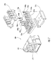
- FIG. 13 is an exploded perspective view of a communications jack according to embodiments of the present invention that includes the contact wire configuration of FIG. 10 with all but two of the contact wires removed.
- This invention is directed to communications connectors, with a primary example of such being a communications jack.
- the terms “forward”, “forwardly”, and “front” and derivatives thereof refer to the direction defined by a vector extending from the center of the jack toward the plug opening of the jack.
- the terms “rearward”, “rearwardly”, and derivatives thereof refer to the direction directly opposite the forward direction; the rearward direction is defined by a vector that extends away from the plug opening toward the remainder of the jack.
- the terms “lateral,” “laterally”, and derivatives thereof refer to the direction generally parallel with the plane defined by a wiring board on which jack contact wires are mounted and extending away from a plane bisecting the plug in the center.
- the terms “medial,” “inward,” “inboard,” and derivatives thereof refer to the direction that is the converse of the lateral direction, i.e., the direction parallel with the plane defined by the wiring board and extending from the periphery of the jack toward the aforementioned bisecting plane.
- the terms “attached”, “connected”, “interconnected”, “contacting”, “mounted” and the like can mean either direct or indirect attachment or contact between elements, unless stated otherwise.
- the terms “coupled,” “induced” and the like can mean non-conductive interaction, either direct or indirect, between elements or between different sections of the same element, unless stated otherwise.
- FIGS. 1 and 1A a prior art jack, designated broadly at 10 , is illustrated in FIGS. 1 and 1A .
- the jack 10 includes a jack frame 12 having a plug aperture 14 for receiving a mating plug, a cover 16 and a terminal housing 18 .
- These components are conventionally formed and not need be described in detail herein; for a further description of these components and the manner in which they interconnect, see U.S. Pat. No. 6,350,158 to Arnett et al., the disclosure of which is hereby incorporated herein in its entirety.
- Those skilled in this art will recognize that other configurations of jack frames, covers and terminal housings may also be employed with the present invention. Exemplary configurations are illustrated in U.S. Pat. Nos. 5,975,919 and 5,947,772 to Arnett et al. and U.S. Pat. No. 6,454,541 to Hashim et al., the disclosure of each of which is hereby incorporated herein in its entirety.
- the jack 10 further includes a wiring board 20 formed of conventional materials.
- the wiring board 20 may be a single layer board or may have multiple layers.
- the wiring board 20 may be substantially planar as illustrated, or may be non-planar.
- contact wires 22 a , 22 b , 24 a , 24 b , 26 a , 26 b , 28 a , 28 b are attached to the wiring board 20 .
- the contact wires 22 a , 22 b , 24 a , 24 b , 26 a , 26 b , 28 a , 28 b have free ends that have substantially the same profile, are substantially transversely aligned in side-by-side relationship, and that extend into the plug aperture 14 to form electrical contact with the terminal blades of a mating plug.
- the free ends of the contact wires 22 a , 22 b , 24 a , 24 b , 26 a , 26 b , 28 a , 28 b extend into individual slots 29 a - 29 h in the forward edge portion of the wiring board 20 .
- the contact wires 22 a , 22 b , 24 a , 24 b , 26 a , 26 b , 28 a , 28 b are arranged in pairs defined by TIA 568B, with wires 22 a , 22 b (pair 1) being adjacent to each other and in the center of the sequence of wires, wires 24 a , 24 b (pair 2) being adjacent to each other and occupying the leftmost two positions (from the vantage point of FIG. 1B ) in the sequence, wires 28 a , 28 b (pair 4) being adjacent to each other and occupying the rightmost two positions (from the vantage point of FIG.
- wires 26 a , 26 b (pair 3) being positioned between, respectively, pairs 1 and 4 and pairs 1 and 2.
- the wires 22 a , 22 b , 24 a , 24 b , 26 a , 26 b , 28 a , 28 b are mounted to the wiring board 20 via insertion into respective apertures 32 a , 32 b , 34 a , 34 b , 36 a , 36 b , 38 a , 38 b , which are arranged in the illustrated embodiment in a “dual diagonal” pattern known to those skilled in this art as described in U.S. Pat. No.
- contact wires or other contacts of other configurations may be used.
- contact wires configured as described in aforementioned U.S. Pat. No. 5,975,919 to Arnett et al. may be employed.
- each of pairs 1, 2 and 4 that comprise adjacent contact wires include a respective “crossover” 22 c , 24 c , 28 c , i.e., a location in which the contact wires of a pair cross each other without making electrical contact, typically such that the free end of one contact wire of the pair is substantially longitudinally aligned with the fixed end portion of the other contact wire of the pair.
- the crossovers 22 c , 24 c , 28 c are located approximately in the center of their contact wires (between the free ends of the contact wires and their mounting locations on the wiring board 20 ). Crossovers are included to provide compensatory crosstalk between contact wires.
- the crossovers are implemented via complementary localized bends in the crossing wires, with one wire being bent upwardly and the other wire being bent downwardly.
- the presence of a crossover, structural implementations thereof, and its effect on crosstalk are discussed in some detail in the '358 patent described above and U.S. Pat. No. 5,186,647 to Denkmann et al., the disclosure of which is hereby incorporated herein by reference.
- the contact wires of pair 3 do not include a crossover.
- IDCs insulation displacement connectors 42 a , 42 b , 44 a , 44 b , 46 a , 46 b , 48 a , 48 b are inserted into eight respective IDC apertures 52 a , 52 b , 54 a , 54 b , 56 a , 56 b , 58 a , 58 b .
- the IDCs are of conventional constriction and need not be described in detail herein; exemplary IDCs are illustrated and described in U.S. Pat. No. 5,975,919 to Arnett, the disclosure of which is hereby incorporated by reference herein in its entirety.
- each of the wire apertures 32 a , 32 b , 34 a , 34 b , 36 a , 36 b , 38 a , 38 b is electrically connected to a respective IDC aperture 52 a , 52 b , 54 a , 54 b , 56 a , 56 b , 58 a , 58 b via a respective conductor 62 a , 62 b , 64 a , 64 b , 66 a , 66 b , 68 a , 68 b , thereby interconnecting each of the contact wires 22 a , 22 b , 24 a , 24 b , 26 a , 26 b , 28 a , 28 b to its corresponding IDC 42 a , 42 b , 44 a , 44 b , 46 a , 46 b , 48 a ,
- the conductors 62 a , 62 b , 64 a , 64 b , 66 a , 66 b , 68 a , 68 b are formed of conventional conductive materials and are deposited on the wiring board 20 via any deposition method known to those skilled in this art to be suitable for the application of conductors. Some conductors are illustrated as being entirely present on a single layer of the wiring board 20 (for example, conductor 62 a ), while other conductors (for example, conductor 62 b ) may reside on multiple layers of the wiring board 20 ; conductors can travel between layers through the inclusion of vias (also known as plated through holes) or other layer-transferring structures known to those skilled in this art.
- vias also known as plated through holes
- the prior art arrangement provides inductive differential to differential crosstalk compensation between pairs 1 and 3, pairs 2 and 3, and pairs 4 and 3, but in the development of the present invention it has been recognized that, due to the large physical separation between the conductors of pair 3 and their asymmetric placement relative to pair 2 (and similarly to pair 4 ), the highest levels of differential to common mode crosstalk in a mating plug, which can be the most problematic to channel performance, tend to occur on pairs 2 and 4 when pair 3 is excited differentially.
- the differential to common mode crosstalk occurring when any of the pairs 1, 2 and 4 is excited differentially tends to be much less severe, and consequently much less problematic, because the separation between the conductors in each of these pairs is one-third the separation between the conductors of pair 3.
- crossover on each of pairs 1, 2 and 4 inductively compensates for the less severe differential to common mode crosstalk occurring when any of these pairs is differentially excited.
- this arrangement not only fails to inductively compensate for the more severe common mode crosstalk on pairs 2 and 4 when pair 3 is differentially excited, but can actually exacerbate this problem. This is especially true when the jack receives a conventional plug such as the one illustrated in U.S. Pat. No. 6,250,949 to Lin.
- the wiring arrangement 120 includes eight contact wires 122 a , 122 b , 124 a , 124 b , 126 a , 126 b , 128 a , 128 b that comprise, respectively, wire pairs 1, 2, 3 and 4.
- the contact wires 122 a , 122 b of pair 1, the contact wires 124 a , 124 b of pair 2, and the contact wires 128 a , 128 b of pair 4 do not include a crossover, while the contact wires 126 a , 126 b include a crossover 126 c.
- this arrangement of contact wires should provide compensatory inductive differential to differential crosstalk between pairs 1 and 3, pairs 2 and 3, and pairs 4 and 3.
- this arrangement although not inductively compensating for the less severe differential to common mode crosstalk occurring when any of the pairs 1, 2 and 4 is differentially excited, can provide inductive compensation for the highly problematic differential to common mode crosstalk occurring on pairs 2 and 4 when pair 3 is differentially excited. Because the most problematic differential to common mode crosstalk can be inductively compensated, a jack employing this arrangement can meet higher performance standards, particularly at elevated frequencies.
- FIGS. 5-7A An exemplary implementation of this arrangement is illustrated in FIGS. 5-7A , in which a jack 200 according to embodiment of the present invention is shown.
- the jack 200 includes a jack frame 212 having a plug aperture 214 , a cover 216 and a terminal housing 218 .
- a wiring board 220 includes IDCs 242 a - 248 b mounted thereon.
- Contact wires 222 a - 228 b are mounted to the wiring board 220 .
- the contact wires 222 a - 228 b fit within slots 229 a - 229 h located at the forward end of the wiring board 220 and are positioned to mate with the blades of a plug inserted into the plug aperture 214 .
- the contact wires 222 a - 228 b follow generally the same profile until they bend downwardly into their respective mounting apertures in the wire board 220 .
- Conductive traces on the wiring board 220 provide signal paths between the contact wires 222 a - 228 b and the IDCs 242 a - 248 b.
- each of the contact wires 226 a , 226 b form the crossover 226 c with the assistance of supports 227 a , 227 b .
- Each of the contact wires 226 a , 226 b includes a transversely-extending crossover segment 231 that travels either over (in the case of the contact wire 226 a ) or under (in the case of contact wire 226 b ) the contact wires 222 a , 222 b .
- Each of the contact wires 226 a , 226 b also includes a support finger 233 that extends rearwardly from the crossover segment 231 to rest atop a respective support 227 a , 227 b .
- the supports 227 a , 227 b extend upwardly from the wiring board 220 from locations approximately halfway between the free ends of the contact wires 226 a , 226 b and their mounting locations 236 a , 236 b in the wiring board 220 .
- the support finger 233 of each contact wire 226 a , 226 b may extend from its crossover segment at substantially the same angle, such that the supports 227 a , 227 b are of different heights in order to support the crossover segment 231 of each contact wire 226 a , 226 b at the proper elevation.
- the supports 227 a , 227 b may be of the same height, and the support finger 231 of each crossover segment may extend therefrom at different angles, or the supports may be of different heights and the fingers may extend at different angles.
- This configuration enables the free ends of the contact wires 226 a , 226 b to deflect in response to the insertion of a plug in the plug aperture 214 without contacting the contact wires 222 a , 222 b .
- the illustrated embodiment has the advantage of enabling the commencement of the inductive differential to differential and differential to common mode compensations at minimal delay from the corresponding crosstalk sources, which can be important to effective crosstalk compensation.
- the separation between the crossover segments 231 and the locations where the contact wires 222 a , 222 b intercept a mating plug is about 0.154 inches, but those skilled in this art will appreciate that a separation gap of a different size may also be suitable with the present invention.
- the contact wires are between about 0.648 and 0.828 inches in length, and the crossover 226 c occurs between about 0.3 and 0.4 inches from the free ends of the contact wires 226 a , 226 b.
- contact wires Although eight contact wires are illustrated and described herein, other numbers of contact wires may be employed. For example, 16 contact wires may be employed, and one or more crossovers that cross over a pair of contact wires sandwiched therebetween may be included in those contact wires.
- jack configurations may also be suitable for use with the present invention.
- other configurations of jack frames, covers and terminal housings may also be employed with the present invention.
- the contact wires may have a different profile (an exemplary alternative profile is depicted in U.S. Pat. No. 5,975,919 to Arnett et al.), or they may by replaced by conductive paths on a flexible circuit, and they may mount in locations that do not follow the “dual diagonal” mounting scheme illustrated herein (an exemplary alternative is illustrated in U.S. Pat. No. 6,116,964 to Goodrich et al).
- the IDCs may mount in a different pattern on the wiring board, or some other type of connector may be used.
- the wiring board described above may be employed in other environments in which a communications jack may be found.
- jacks within a patch panel or series of patch panels may be suitable for use with such wiring boards.
- Other environments may also be possible.
- the contact wires may not include any crossovers on any of the pairs, but rather the wiring board to which they are attached can have its signal carrying conductive paths routed in accordance with the crossover scheme described generally in FIG. 4 .
- crossover of pair 3 described above can be implemented, with similar beneficial effect on differential to common mode crosstalk conversion, by forming the conductor leads of jacks utilizing metallic lead-frame structures instead of printed wiring boards to achieve the required connectivity and crosstalk compensation.
- the contact wires and/or the insulation displacement connectors may be formed integrally with the conductors as unitary members.
- a connector such as that illustrated in FIGS. 5-7A and mated with a conventional plug may have channel alien NEXT of less than ⁇ 60 dB power sum at 100 MHz, and less than ⁇ 49.5 dB power sum at 500 MHz.
- Communication jacks of the configuration illustrated in FIG. 1 were modeled and solved using finite element electromagnetic field simulation software.
- one jack model designated “experimental jack”
- the contact wire crossover configuration substantially matched the embodiment of the current invention illustrated in FIGS. 5-7A .
- a second jack model designated “prior art jack”
- the contact wire crossover configuration substantially matched the prior art jack illustrated in FIGS. 1-3 .
- the jack models were then solved for differential to common mode NEXT and FEXT crosstalk.
- FIGS. 10-13 illustrate a communications jack 300 according to further embodiments of the present invention.
- FIG. 10 illustrates the contact wire configuration for the jack 300
- FIG. 11 shows how two of the contact wires of FIG. 10 may interact with a plurality of stops
- FIG. 12 illustrates one implementation for two of the stops of FIG. 11
- FIG. 13 is an exploded perspective view of the entire jack 300 with six of the contact wires removed.
- the jack 300 includes a jack frame 312 having a plug aperture 314 for receiving a mating plug, a cover 316 , a terminal housing 318 , a wiring board 320 , and a plurality of insulation displacement connectors (IDCs) 342 a , 342 b , 344 a , 344 b , 346 a , 346 b , 348 a , 348 b .
- the wiring board 320 is located at least partially within the housing of the jack 300 (in jack 300 the housing comprises the jack frame 312 , the cover 316 and the terminal housing 318 ).
- the jack 300 further includes eight contact wires 322 a , 322 b , 324 a , 324 b , 326 a , 326 b , 328 a , 328 b .
- the free ends of the contact wires 322 a , 322 b , 324 a , 324 b , 326 a , 326 b , 328 a , 328 b have substantially the same profile and are substantially transversely aligned in side-by-side relationship.
- FIG. 10 the jack 300 further includes eight contact wires 322 a , 322 b , 324 a , 324 b , 326 a , 326 b , 328 a , 328 b .
- the free ends of the contact wires 322 a , 322 b , 324 a , 324 b , 326 a , 326 b , 328 a , 328 b extend into the plug aperture 314 of the jack to form electrical contact with the blades of a mating plug (not shown in FIGS. 10-13 ).
- the free ends of the contact wires 322 a , 322 b , 324 a , 324 b , 326 a , 326 b , 328 a , 328 b extend into individual slots 329 a - 329 h in the forward edge portion of the wiring board 320 .
- the contact wires 322 a , 322 b , 324 a , 324 b , 326 a , 326 b , 328 a , 328 b are arranged in pairs defined by TIA 568B, and are mounted to the wiring board 320 via insertion into respective apertures (not shown) in the wiring board 320 .
- the contact wires 322 a , 322 b , 324 a , 324 b , 326 a , 326 b , 328 a , 328 b are electrically connected to the IDCs 342 a , 342 b , 344 a , 344 b , 346 a , 346 b , 348 a , 348 b via conductors (not shown) formed on and/or in the wiring board 320 .
- the eight contact wires 322 a , 322 b , 324 a , 324 b , 326 a , 326 b , 328 a , 328 b comprise, respectively, wire pairs 1, 2, 3 and 4.
- the contact wires 322 a , 322 b of pair 1, the contact wires 324 a , 324 b of pair 2, and the contact wires 328 a , 328 b of pair 4 do not include a crossover, while the contact wires 326 a , 326 b include a crossover.
- this contact wire arrangement should provide compensatory inductive differential to differential crosstalk between pairs 1 and 3, pairs 2 and 3, and pairs 4 and 3, as well as inductive compensation for the differential to common mode crosstalk occurring on pairs 2 and 4 when pair 3 is differentially excited.
- the contact wires 326 a , 326 b of pair 3 each include a fixed end portion 362 , 372 that includes a termination (also referred to as a “fixed end”) 361 , 371 that is mounted in the wiring board 320 , a deflectable free end portion 363 , 373 , and a support finger 366 , 376 .
- the deflectable free end portion of each contact wire 326 a , 326 b includes a crossover segment 363 , 373 and a plug contact region 364 , 374 where each contact 326 a , 326 b contacts a respective blade of a mating plug.
- the portion of contact wire 326 a forming a direct path between the fixed end 361 and the far end of the free end portion 363 comprises an intermediate portion of the contact wire 326 a .
- the support finger 366 branches off of this intermediate portion.
- the portion of contact wire 326 b forming a direct path between the fixed end 371 and the far end of the free end portion 373 comprises an intermediate portion of the contact wire 326 b .
- the support finger 376 branches off of this intermediate portion.
- the crossover segments 363 , 373 are transversely-extending crossover segments that travel either over (in the case of the contact wire 326 b ) or under (in the case of contact wire 326 a ) the contact wires 322 a , 322 b .
- the support fingers 366 , 376 each extend rearwardly from the crossover segment 363 , 373 , and each support finger includes a respective distal end 367 , 377 . As shown in FIG. 12 , the distal ends 367 , 377 of the support fingers 366 , 376 rest atop respective supports 327 a , 327 b .
- the supports 327 a , 327 b are at different elevations above the top surface of the wiring board 320 in order to support the respective crossover segments 363 , 373 of contact wires 326 a , 326 b at the proper elevation. It will be appreciated, however, that in other embodiments, the supports 327 a , 327 b may be of the same height and/or that the support fingers 366 , 376 of each crossover segment may extend therefrom at different angles, or the supports may be of different heights and the fingers may extend at different angles.
- the plug contact region 364 , 374 of contacts 326 a , 326 b may be offset by a relatively large distance from the respective fixed end 361 , 371 of each contact. As such, the contacts 326 a , 326 b may not have sufficient support which, in certain circumstances, may allow one or both of the contacts 326 a , 326 b to make physical and electrical contact with one or both of contacts 322 a , 322 b when the contacts of the jack 300 are deflected as a mating connector is received within the plug aperture 314 .
- each contact 326 a , 326 b may include a respective support finger 366 , 376 that engages a respective support element 327 a , 327 b to ensure that sufficient support is provided so that such short-circuiting of either or both contacts 326 a , 326 b will not occur.
- the distal ends 367 , 377 of the respective support fingers 366 , 376 do not terminate into the wiring board 320 in this particular embodiment of the present invention, as the signal carrying path to the wiring board is through the crossover segment 363 and fixed end portion 362 for contact 326 a and through the crossover segment 373 and fixed end portion 372 for contact 326 b .
- the distal ends 367 , 377 of the support fingers 366 , 376 engage respective supports 327 a , 327 b (see FIG. 12 ) to provide sufficient support so that the contact wires 326 a , 326 b do not make physical contact with any of the other contact wires during normal operation of the jack 300 .
- the support finger 366 and the free end 365 of contact 326 a may form a beam structure 368 .
- This beam structure 368 may absorb all or practically all of the strain experienced by the contact wire 326 a in response to insertion of a mating plug into the plug aperture 314 , and thus provides the contact force that holds the contact 326 a against a corresponding blade of the plug such that a reliable electrical connection is established between the plug blade and contact 326 a .
- the crossover segment 363 of contact 326 a and the fixed end portion 362 need not absorb any of the strain for contact wire 326 a .
- the crossover segment 363 of contact 326 a and the fixed end portion 362 could be replaced by electrical lead wires (i.e., non-flexure members) that merely provide a conductive path from the contact 326 a onto the wiring board 320 .
- the support finger 376 and the free end 375 of contact 326 b may form a beam structure 378 .
- This beam structure 378 may absorb all or practically all of the strain experienced by contact wire 326 b in response to insertion of a mating plug into the plug aperture 314 , and thus provides the contact force that holds the contact 326 b against a corresponding blade of the plug such that a reliable electrical connection is established between the plug blade and contact 326 b .
- the crossover segment 373 of contact 326 b and the fixed end portion 372 need not absorb any of the strain for contact wire 326 b.
- a plurality of stops 351 - 354 may be included in the connector 300 .
- a stop 353 may be provided adjacent the free end 365 of contact 326 a
- a stop 351 may be provided adjacent the free end 375 of contact 326 b
- a stop 354 may be provided adjacent the distal end 367 of the support finger 366 of contact 326 a
- a stop 352 may be provided adjacent the distal end 377 of the support finger 376 of contact 326 b .
- These stops 351 - 354 may be implemented, for example, as plastic walls in the contact dividing structure 369 , although it will be appreciated that numerous other ways of implementing these stops are possible.
- the plastic stops 354 and 352 may facilitate preventing over-bending of the crossover segments 363 and 373 , respectively, when a mating plug is inserted into the plug aperture 314 .
- the plastic stops 353 and 351 may facilitate preventing over-bending of the crossover segments 363 and 373 when a mating plug is removed from the plug aperture 314 .
- the free ends 365 , 375 of the contacts 326 a , 326 b may likewise be supported by the top surface of the wiring board 320 when a mating plug is received in the jack aperture 314 (and may or may not engage the wiring board 320 in the absence of a mating plug).
- both the distal ends 367 , 377 of the support fingers 366 , 376 and the free ends 365 , 375 of the contacts 326 a , 326 b may move some distance when a mating plug is inserted into and/or removed from the plug aperture until these ends engage the respective stops 351 - 354 which prevent further movement.
- the free ends 365 , 375 of the contact wires 326 a , 326 b deflect in response to the insertion of a plug in the plug aperture 314 without contacting the contact wires 322 a , 322 b .
- the illustrated embodiment has the advantage of enabling the commencement of the inductive differential to differential and differential to common mode compensations at minimal delay from the corresponding crosstalk sources, which can be important to effective crosstalk compensation.
- the separation between the crossover segments 363 , 373 and the location where the contact wires 322 a , 322 b intercept a mating plug is about 0.15 inches, but those skilled in this art will appreciate that a separation gap of a different size may also be suitable with the present invention.
Abstract
Description
Claims (20)
Priority Applications (1)
| Application Number | Priority Date | Filing Date | Title |
|---|---|---|---|
| US11/688,458 US7320624B2 (en) | 2004-12-16 | 2007-03-20 | Communications jacks with compensation for differential to differential and differential to common mode crosstalk |
Applications Claiming Priority (3)
| Application Number | Priority Date | Filing Date | Title |
|---|---|---|---|
| US63659504P | 2004-12-16 | 2004-12-16 | |
| US11/088,044 US7204722B2 (en) | 2004-12-07 | 2005-03-23 | Communications jack with compensation for differential to differential and differential to common mode crosstalk |
| US11/688,458 US7320624B2 (en) | 2004-12-16 | 2007-03-20 | Communications jacks with compensation for differential to differential and differential to common mode crosstalk |
Related Parent Applications (1)
| Application Number | Title | Priority Date | Filing Date |
|---|---|---|---|
| US11/088,044 Continuation-In-Part US7204722B2 (en) | 2004-12-07 | 2005-03-23 | Communications jack with compensation for differential to differential and differential to common mode crosstalk |
Publications (2)
| Publication Number | Publication Date |
|---|---|
| US20070178772A1 US20070178772A1 (en) | 2007-08-02 |
| US7320624B2 true US7320624B2 (en) | 2008-01-22 |
Family
ID=38322672
Family Applications (1)
| Application Number | Title | Priority Date | Filing Date |
|---|---|---|---|
| US11/688,458 Active US7320624B2 (en) | 2004-12-16 | 2007-03-20 | Communications jacks with compensation for differential to differential and differential to common mode crosstalk |
Country Status (1)
| Country | Link |
|---|---|
| US (1) | US7320624B2 (en) |
Cited By (15)
| Publication number | Priority date | Publication date | Assignee | Title |
|---|---|---|---|---|
| US20080293289A1 (en) * | 2004-11-17 | 2008-11-27 | Virak Siev | Balanced interconnector |
| US20090225979A1 (en) * | 2004-11-17 | 2009-09-10 | Belden Cdt (Canada) Inc. | Crosstalk Reducing Conductor and Contact Configuration in a Communication System |
| US20100041250A1 (en) * | 2007-01-18 | 2010-02-18 | Adc Gmbh | Electrical contact arrangement for telecommunications and data systems technology |
| US7682203B1 (en) | 2008-11-04 | 2010-03-23 | Commscope, Inc. Of North Carolina | Communications jacks having contact wire configurations that provide crosstalk compensation |
| US20100159752A1 (en) * | 2008-12-22 | 2010-06-24 | Virak Siev | Coupler connector |
| US7914346B2 (en) | 2008-11-04 | 2011-03-29 | Commscope, Inc. Of North Carolina | Communications jacks having contact wire configurations that provide crosstalk compensation |
| US7967614B1 (en) * | 2010-04-28 | 2011-06-28 | Tyco Electronics Corporation | Plug connector and connector assembly having a pluggable board substrate |
| US20140073196A1 (en) * | 2012-09-07 | 2014-03-13 | Commscope, Inc. Of North Carolina | High Performance Communications Jacks Having Crosstalk Compensation and/or Return Loss Improvement Circuitry |
| US8801473B2 (en) | 2012-09-12 | 2014-08-12 | Panduit Corp. | Communication connector having a plurality of conductors with a coupling zone |
| US9088116B2 (en) | 2011-11-23 | 2015-07-21 | Panduit Corp. | Compensation network using an orthogonal compensation network |
| US9136647B2 (en) | 2012-06-01 | 2015-09-15 | Panduit Corp. | Communication connector with crosstalk compensation |
| US9246463B2 (en) | 2013-03-07 | 2016-01-26 | Panduit Corp. | Compensation networks and communication connectors using said compensation networks |
| US9246274B2 (en) | 2013-03-15 | 2016-01-26 | Panduit Corp. | Communication connectors having crosstalk compensation networks |
| US9257792B2 (en) | 2013-03-14 | 2016-02-09 | Panduit Corp. | Connectors and systems having improved crosstalk performance |
| US10587081B2 (en) * | 2017-03-14 | 2020-03-10 | Panduit Corp. | Communication connectors and components thereof |
Families Citing this family (18)
| Publication number | Priority date | Publication date | Assignee | Title |
|---|---|---|---|---|
| US7364470B2 (en) * | 2006-07-05 | 2008-04-29 | Commscope, Inc. Of North Carolina | Communications connectors with signal current splitting |
| US7794286B2 (en) * | 2008-12-12 | 2010-09-14 | Hubbell Incorporated | Electrical connector with separate contact mounting and compensation boards |
| US8235731B1 (en) * | 2011-03-18 | 2012-08-07 | Leviton Manufacturing Co., Ltd. | Connector module and patch panel |
| JP2012208897A (en) * | 2011-03-30 | 2012-10-25 | Semiconductor Components Industries Llc | Input/output circuit |
| US9627816B2 (en) | 2012-02-13 | 2017-04-18 | Sentinel Connector System Inc. | High speed grounded communication jack |
| US8858266B2 (en) | 2012-02-13 | 2014-10-14 | Sentinel Connector Systems, Inc. | High speed communication jack |
| US9337592B2 (en) | 2012-02-13 | 2016-05-10 | Sentinel Connector Systems, Inc. | High speed communication jack |
| US9653847B2 (en) | 2013-01-11 | 2017-05-16 | Sentinel Connector System, Inc. | High speed communication jack |
| US9147977B2 (en) | 2012-07-05 | 2015-09-29 | Leviton Manufacturing Co., Inc. | High density high speed data communications connector |
| US8858267B2 (en) * | 2013-03-14 | 2014-10-14 | Commscope, Inc. Of North Carolina | Communications plugs and patch cords with mode conversion control circuitry |
| US8858268B2 (en) | 2013-03-14 | 2014-10-14 | Commscope, Inc. Of North Carolina | Communications plugs and patch cords with mode conversion control circuitry |
| US8864532B2 (en) * | 2013-03-15 | 2014-10-21 | Commscope, Inc. Of North Carolina | Communications jacks having low crosstalk and/or solder-less wire connection assemblies |
| US9088106B2 (en) * | 2013-05-14 | 2015-07-21 | Commscope, Inc. Of North Carolina | Communications jacks having flexible printed circuit boards with common mode crosstalk compensation |
| RU2017114931A (en) | 2014-10-01 | 2018-11-02 | Сентинл Коннектор Системз, Инк. | HIGH SPEED CONNECTOR |
| US9912083B2 (en) | 2015-07-21 | 2018-03-06 | Sentinel Connector Systems, Inc. | High speed plug |
| CA3021559A1 (en) | 2016-05-04 | 2017-11-09 | Sentinel Connector Systems, Inc. | Large conductor industrial plug |
| CN110854573B (en) * | 2019-11-22 | 2021-02-09 | 维沃移动通信有限公司 | Plug of data transmission line and data transmission line |
| US11811163B2 (en) | 2021-02-26 | 2023-11-07 | Leviton Manufacturing Co., Inc. | Mutoa and quad floating connector |
Citations (76)
| Publication number | Priority date | Publication date | Assignee | Title |
|---|---|---|---|---|
| US5186647A (en) | 1992-02-24 | 1993-02-16 | At&T Bell Laboratories | High frequency electrical connector |
| WO1994005092A1 (en) | 1992-08-24 | 1994-03-03 | British Telecommunications Public Limited Company | Apparatus and method for crosstalk cancellation in data correctors |
| US5299956A (en) | 1992-03-23 | 1994-04-05 | Superior Modular Products, Inc. | Low cross talk electrical connector system |
| US5326284A (en) | 1992-06-25 | 1994-07-05 | Northern Telecom Limited | Circuit assemblies of printed circuit boards and telecommunications connectors |
| US5328390A (en) | 1992-09-01 | 1994-07-12 | Hubbell Incorporated | Modular telecommunication jack adapter |
| US5362257A (en) | 1993-07-08 | 1994-11-08 | The Whitaker Corporation | Communications connector terminal arrays having noise cancelling capabilities |
| US5397862A (en) | 1993-08-31 | 1995-03-14 | Motorola, Inc. | Horizontally twisted-pair planar conductor line structure |
| US5414393A (en) | 1992-08-20 | 1995-05-09 | Hubbell Incorporated | Telecommunication connector with feedback |
| US5432484A (en) | 1992-08-20 | 1995-07-11 | Hubbell Incorporated | Connector for communication systems with cancelled crosstalk |
| EP0525703B1 (en) | 1991-08-01 | 1995-11-29 | Siemens Aktiengesellschaft | Connector for local networks |
| US5547405A (en) | 1993-12-03 | 1996-08-20 | Itt Industries Limited | Crosstalk suppressing connector |
| US5571035A (en) | 1994-10-31 | 1996-11-05 | The Whitaker Corporation | Divergent load bar |
| US5587884A (en) | 1995-02-06 | 1996-12-24 | The Whitaker Corporation | Electrical connector jack with encapsulated signal conditioning components |
| US5618185A (en) | 1995-03-15 | 1997-04-08 | Hubbell Incorporated | Crosstalk noise reduction connector for telecommunication system |
| US5779503A (en) | 1996-12-18 | 1998-07-14 | Nordx/Cdt, Inc. | High frequency connector with noise cancelling characteristics |
| EP0901201A1 (en) | 1997-09-02 | 1999-03-10 | Lucent Technologies Inc. | Electrical connector having time-delayed signal compensation |
| US5911602A (en) | 1996-07-23 | 1999-06-15 | Superior Modular Products Incorporated | Reduced cross talk electrical connector |
| US5915989A (en) | 1997-05-19 | 1999-06-29 | Lucent Technologies Inc. | Connector with counter-balanced crosswalk compensation scheme |
| US5921818A (en) | 1997-06-23 | 1999-07-13 | Lucent Technologies Inc. | Low crosstalk electrical connector |
| US5947772A (en) | 1997-08-22 | 1999-09-07 | Lucent Technologies Inc. | Wire terminal block for communication connectors |
| US5961354A (en) | 1997-01-13 | 1999-10-05 | Lucent Technologies, Inc. | Electrical connector assembly |
| US5967853A (en) | 1997-06-24 | 1999-10-19 | Lucent Technologies Inc. | Crosstalk compensation for electrical connectors |
| WO1999053574A1 (en) | 1998-04-16 | 1999-10-21 | Thomas & Betts International, Inc. | Crosstalk reducing electrical jack and plug connector |
| US5971813A (en) | 1998-04-01 | 1999-10-26 | Regal Electronics, Inc. | RJ-45 modular connector with microwave-transmission-line integrated signal conditioning for high speed networks |
| US5975919A (en) | 1997-08-26 | 1999-11-02 | Lucent Technologies Inc. | Terminal housing and wire board arrangement with solderless mountable insulation displacement connector terminals |
| US5989071A (en) | 1997-09-03 | 1999-11-23 | Lucent Technologies Inc. | Low crosstalk assembly structure for use in a communication plug |
| US6017247A (en) | 1997-03-05 | 2000-01-25 | Krone Aktiengesellschaft | Arrangement of contact pairs for compensation of near-end crosstalk |
| US6042427A (en) | 1998-06-30 | 2000-03-28 | Lucent Technologies Inc. | Communication plug having low complementary crosstalk delay |
| US6050843A (en) | 1997-07-31 | 2000-04-18 | Lucent Technologies Inc. | Crosstalk canceling 110 index strip and wiring block |
| US6102730A (en) | 1995-09-01 | 2000-08-15 | Cekan/Cdt A/S | Connector element for telecommunications |
| US6116964A (en) | 1999-03-08 | 2000-09-12 | Lucent Technologies Inc. | High frequency communications connector assembly with crosstalk compensation |
| US6120330A (en) | 1998-05-20 | 2000-09-19 | Krone Gmbh | Arrangement of contact pairs for compensating near-end crosstalk for an electric patch plug |
| EP1059704A2 (en) | 1999-06-08 | 2000-12-13 | Lucent Technologies Inc. | Communication connector assembly with crosstalk compensation |
| US6165023A (en) | 1999-10-28 | 2000-12-26 | Lucent Technologies Inc. | Capacitive crosstalk compensation arrangement for a communication connector |
| US6170154B1 (en) | 1997-10-24 | 2001-01-09 | Com Dev Limited | Printed lumped element stripline circuit structure and method |
| US6196880B1 (en) | 1999-09-21 | 2001-03-06 | Avaya Technology Corp. | Communication connector assembly with crosstalk compensation |
| US6238235B1 (en) | 1999-05-10 | 2001-05-29 | Rit Technologies Ltd. | Cable organizer |
| US6270358B1 (en) | 1999-04-01 | 2001-08-07 | Infra+ | Low-voltage male connector |
| US6270381B1 (en) | 2000-07-07 | 2001-08-07 | Avaya Technology Corp. | Crosstalk compensation for electrical connectors |
| US20010018287A1 (en) | 2000-02-24 | 2001-08-30 | Hans Reichle | Adapter and plug for communications and control engineering |
| US6312290B1 (en) | 1997-06-23 | 2001-11-06 | Fci Americas Technology, Inc. | High speed IDC modular jack |
| US20010048592A1 (en) | 2000-05-31 | 2001-12-06 | Kabushiki Kaisha Toshiba. | Printed circuit board and electronic equipment using the board |
| US6350158B1 (en) | 2000-09-19 | 2002-02-26 | Avaya Technology Corp. | Low crosstalk communication connector |
| US6353540B1 (en) | 1995-01-10 | 2002-03-05 | Hitachi, Ltd. | Low-EMI electronic apparatus, low-EMI circuit board, and method of manufacturing the low-EMI circuit board. |
| US6356162B1 (en) | 1999-04-02 | 2002-03-12 | Nordx/Cdt, Inc. | Impedance compensation for a cable and connector |
| US6364694B1 (en) | 2001-01-19 | 2002-04-02 | M M E Corporation | Modular communications socket |
| US6379157B1 (en) | 2000-08-18 | 2002-04-30 | Leviton Manufacturing Co., Inc. | Communication connector with inductive compensation |
| US6379198B1 (en) | 2000-03-13 | 2002-04-30 | Avaya Technology Corp. | Electrical connector terminal construction |
| US6407542B1 (en) | 2000-03-23 | 2002-06-18 | Avaya Technology Corp. | Implementation of a multi-port modal decomposition system |
| US20020088977A1 (en) | 2001-01-03 | 2002-07-11 | Toru Mori | Stacked capacitor and method of forming the same as well as semiconductor device using the same and circuit board using the same |
| US6428362B1 (en) | 1999-08-20 | 2002-08-06 | Adc Telecommunications, Inc. | Jack including crosstalk compensation for printed circuit board |
| US6443777B1 (en) | 2001-06-22 | 2002-09-03 | Avaya Technology Corp. | Inductive crosstalk compensation in a communication connector |
| US6443776B2 (en) | 2000-02-21 | 2002-09-03 | Reichle & De-Massari Ag | Plug connector part |
| US6454541B1 (en) | 1999-10-12 | 2002-09-24 | Nippon Shokubai Co., Ltd. | Method for transferring easily-polymerizable substance |
| US6464529B1 (en) | 1993-03-12 | 2002-10-15 | Cekan/Cdt A/S | Connector element for high-speed data communications |
| US6520807B2 (en) | 1999-11-12 | 2003-02-18 | Fci Americas Technology, Inc. | Electrical connector system with low cross-talk |
| US6524128B2 (en) | 2000-06-02 | 2003-02-25 | Stewart Connector Systems, Inc. | Modular plug wire aligner |
| WO2003019734A1 (en) | 2001-08-23 | 2003-03-06 | Rit Technologies Ltd. | High data rate interconnecting device |
| US6558204B1 (en) | 1999-02-19 | 2003-05-06 | Richard Weatherley | Plug assembly for data transmission and method of wiring same |
| US6558207B1 (en) | 2000-10-25 | 2003-05-06 | Tyco Electronics Corporation | Electrical connector having stamped electrical contacts with deformed sections for increased stiffness |
| US6561838B1 (en) | 1999-12-13 | 2003-05-13 | Adc Telecommunications, Inc. | Connector plug and insert for twisted pair cables |
| US6571187B1 (en) | 2000-02-09 | 2003-05-27 | Avaya Technology Corp. | Method for calibrating two port high frequency measurements |
| US20030129880A1 (en) | 2002-01-04 | 2003-07-10 | Arnett Jaime Ray | Communication jack that withstands insertion of a communication plug that the jack is not specifically configured to mate with without being damaged |
| US6592395B2 (en) | 2001-10-03 | 2003-07-15 | Avaya Technology Corp. | In-line cable connector assembly |
| WO2003090322A1 (en) | 2002-04-16 | 2003-10-30 | Pulse Engineering | Shielded connector assembly and method of manufacturing |
| US6647357B1 (en) | 2000-02-07 | 2003-11-11 | Avaya Technology Corp. | Method for correcting reciprocity error in two port network measurements |
| US20040002267A1 (en) | 2002-03-12 | 2004-01-01 | Peter Hatterscheid | Electrical plug connector for information technology |
| US6716964B1 (en) | 1997-12-12 | 2004-04-06 | Saint Louis University | CtIP, a novel protein that interacts with CtBP and uses therefor |
| EP1435679A1 (en) | 2002-11-27 | 2004-07-07 | Panduit Corporation | Electronic connector and method of performing electronic connection |
| US6764348B2 (en) | 2002-11-21 | 2004-07-20 | Dae Eun Electronics Co., Ltd. | Modular jack |
| US6811442B1 (en) | 2003-12-11 | 2004-11-02 | Superworld Electronics Co., Ltd. | Positioning seat with nests for coils for a connector |
| US6962503B2 (en) | 2000-01-10 | 2005-11-08 | Ortronics, Inc. | Unshielded twisted pair (UTP) wire stabilizer for communication plug |
| US20050254223A1 (en) | 2004-05-14 | 2005-11-17 | Amid Hashim | Next high frequency improvement by using frequency dependent effective capacitance |
| US20060121789A1 (en) | 2004-12-06 | 2006-06-08 | Amid Hashim | Communications connector with floating wiring board for imparting crosstalk compensation between conductors |
| US20060121788A1 (en) | 2004-12-07 | 2006-06-08 | Pharney Julian R | Communication plug with balanced wiring to reduce differential to common mode crosstalk |
| US20060160428A1 (en) | 2004-12-07 | 2006-07-20 | Amid Hashim | Communications jack with compensation for differential to differential and differential to common mode crosstalk |
Family Cites Families (1)
| Publication number | Priority date | Publication date | Assignee | Title |
|---|---|---|---|---|
| US5991358A (en) * | 1997-12-31 | 1999-11-23 | Analogic Corporation | Data acquisition system for generating accurate projection data in a CT scanner |
-
2007
- 2007-03-20 US US11/688,458 patent/US7320624B2/en active Active
Patent Citations (83)
| Publication number | Priority date | Publication date | Assignee | Title |
|---|---|---|---|---|
| EP0525703B1 (en) | 1991-08-01 | 1995-11-29 | Siemens Aktiengesellschaft | Connector for local networks |
| US5186647A (en) | 1992-02-24 | 1993-02-16 | At&T Bell Laboratories | High frequency electrical connector |
| US5299956A (en) | 1992-03-23 | 1994-04-05 | Superior Modular Products, Inc. | Low cross talk electrical connector system |
| US5310363A (en) | 1992-03-23 | 1994-05-10 | Superior Modular Products Incorporated | Impedance matched reduced cross talk electrical connector system |
| US5299956B1 (en) | 1992-03-23 | 1995-10-24 | Superior Modular Prod Inc | Low cross talk electrical connector system |
| US5326284A (en) | 1992-06-25 | 1994-07-05 | Northern Telecom Limited | Circuit assemblies of printed circuit boards and telecommunications connectors |
| US5432484A (en) | 1992-08-20 | 1995-07-11 | Hubbell Incorporated | Connector for communication systems with cancelled crosstalk |
| US5414393A (en) | 1992-08-20 | 1995-05-09 | Hubbell Incorporated | Telecommunication connector with feedback |
| WO1994005092A1 (en) | 1992-08-24 | 1994-03-03 | British Telecommunications Public Limited Company | Apparatus and method for crosstalk cancellation in data correctors |
| US5328390A (en) | 1992-09-01 | 1994-07-12 | Hubbell Incorporated | Modular telecommunication jack adapter |
| US6464529B1 (en) | 1993-03-12 | 2002-10-15 | Cekan/Cdt A/S | Connector element for high-speed data communications |
| US5362257A (en) | 1993-07-08 | 1994-11-08 | The Whitaker Corporation | Communications connector terminal arrays having noise cancelling capabilities |
| US5397862A (en) | 1993-08-31 | 1995-03-14 | Motorola, Inc. | Horizontally twisted-pair planar conductor line structure |
| US5547405A (en) | 1993-12-03 | 1996-08-20 | Itt Industries Limited | Crosstalk suppressing connector |
| US5571035A (en) | 1994-10-31 | 1996-11-05 | The Whitaker Corporation | Divergent load bar |
| US6353540B1 (en) | 1995-01-10 | 2002-03-05 | Hitachi, Ltd. | Low-EMI electronic apparatus, low-EMI circuit board, and method of manufacturing the low-EMI circuit board. |
| US5587884A (en) | 1995-02-06 | 1996-12-24 | The Whitaker Corporation | Electrical connector jack with encapsulated signal conditioning components |
| US5618185A (en) | 1995-03-15 | 1997-04-08 | Hubbell Incorporated | Crosstalk noise reduction connector for telecommunication system |
| US6102730A (en) | 1995-09-01 | 2000-08-15 | Cekan/Cdt A/S | Connector element for telecommunications |
| US5911602A (en) | 1996-07-23 | 1999-06-15 | Superior Modular Products Incorporated | Reduced cross talk electrical connector |
| US5779503A (en) | 1996-12-18 | 1998-07-14 | Nordx/Cdt, Inc. | High frequency connector with noise cancelling characteristics |
| US5961354A (en) | 1997-01-13 | 1999-10-05 | Lucent Technologies, Inc. | Electrical connector assembly |
| US6017247A (en) | 1997-03-05 | 2000-01-25 | Krone Aktiengesellschaft | Arrangement of contact pairs for compensation of near-end crosstalk |
| US5915989A (en) | 1997-05-19 | 1999-06-29 | Lucent Technologies Inc. | Connector with counter-balanced crosswalk compensation scheme |
| US6312290B1 (en) | 1997-06-23 | 2001-11-06 | Fci Americas Technology, Inc. | High speed IDC modular jack |
| US5921818A (en) | 1997-06-23 | 1999-07-13 | Lucent Technologies Inc. | Low crosstalk electrical connector |
| US5967853A (en) | 1997-06-24 | 1999-10-19 | Lucent Technologies Inc. | Crosstalk compensation for electrical connectors |
| US6050843A (en) | 1997-07-31 | 2000-04-18 | Lucent Technologies Inc. | Crosstalk canceling 110 index strip and wiring block |
| US5947772A (en) | 1997-08-22 | 1999-09-07 | Lucent Technologies Inc. | Wire terminal block for communication connectors |
| US5975919A (en) | 1997-08-26 | 1999-11-02 | Lucent Technologies Inc. | Terminal housing and wire board arrangement with solderless mountable insulation displacement connector terminals |
| EP0901201A1 (en) | 1997-09-02 | 1999-03-10 | Lucent Technologies Inc. | Electrical connector having time-delayed signal compensation |
| US5997358A (en) | 1997-09-02 | 1999-12-07 | Lucent Technologies Inc. | Electrical connector having time-delayed signal compensation |
| US5989071A (en) | 1997-09-03 | 1999-11-23 | Lucent Technologies Inc. | Low crosstalk assembly structure for use in a communication plug |
| US6170154B1 (en) | 1997-10-24 | 2001-01-09 | Com Dev Limited | Printed lumped element stripline circuit structure and method |
| US6716964B1 (en) | 1997-12-12 | 2004-04-06 | Saint Louis University | CtIP, a novel protein that interacts with CtBP and uses therefor |
| US5971813A (en) | 1998-04-01 | 1999-10-26 | Regal Electronics, Inc. | RJ-45 modular connector with microwave-transmission-line integrated signal conditioning for high speed networks |
| US20010021608A1 (en) | 1998-04-16 | 2001-09-13 | Thomas & Betts International, Inc. | Crosstalk reducing electrical jack and plug connector |
| WO1999053574A1 (en) | 1998-04-16 | 1999-10-21 | Thomas & Betts International, Inc. | Crosstalk reducing electrical jack and plug connector |
| US6120330A (en) | 1998-05-20 | 2000-09-19 | Krone Gmbh | Arrangement of contact pairs for compensating near-end crosstalk for an electric patch plug |
| US6042427A (en) | 1998-06-30 | 2000-03-28 | Lucent Technologies Inc. | Communication plug having low complementary crosstalk delay |
| US6558204B1 (en) | 1999-02-19 | 2003-05-06 | Richard Weatherley | Plug assembly for data transmission and method of wiring same |
| US6116964A (en) | 1999-03-08 | 2000-09-12 | Lucent Technologies Inc. | High frequency communications connector assembly with crosstalk compensation |
| US6270358B1 (en) | 1999-04-01 | 2001-08-07 | Infra+ | Low-voltage male connector |
| US6356162B1 (en) | 1999-04-02 | 2002-03-12 | Nordx/Cdt, Inc. | Impedance compensation for a cable and connector |
| US6238235B1 (en) | 1999-05-10 | 2001-05-29 | Rit Technologies Ltd. | Cable organizer |
| EP1059704A2 (en) | 1999-06-08 | 2000-12-13 | Lucent Technologies Inc. | Communication connector assembly with crosstalk compensation |
| US6186834B1 (en) | 1999-06-08 | 2001-02-13 | Avaya Technology Corp. | Enhanced communication connector assembly with crosstalk compensation |
| US6428362B1 (en) | 1999-08-20 | 2002-08-06 | Adc Telecommunications, Inc. | Jack including crosstalk compensation for printed circuit board |
| US6196880B1 (en) | 1999-09-21 | 2001-03-06 | Avaya Technology Corp. | Communication connector assembly with crosstalk compensation |
| US6454541B1 (en) | 1999-10-12 | 2002-09-24 | Nippon Shokubai Co., Ltd. | Method for transferring easily-polymerizable substance |
| US6165023A (en) | 1999-10-28 | 2000-12-26 | Lucent Technologies Inc. | Capacitive crosstalk compensation arrangement for a communication connector |
| US6520807B2 (en) | 1999-11-12 | 2003-02-18 | Fci Americas Technology, Inc. | Electrical connector system with low cross-talk |
| US6561838B1 (en) | 1999-12-13 | 2003-05-13 | Adc Telecommunications, Inc. | Connector plug and insert for twisted pair cables |
| US6962503B2 (en) | 2000-01-10 | 2005-11-08 | Ortronics, Inc. | Unshielded twisted pair (UTP) wire stabilizer for communication plug |
| US6647357B1 (en) | 2000-02-07 | 2003-11-11 | Avaya Technology Corp. | Method for correcting reciprocity error in two port network measurements |
| US6571187B1 (en) | 2000-02-09 | 2003-05-27 | Avaya Technology Corp. | Method for calibrating two port high frequency measurements |
| US6443776B2 (en) | 2000-02-21 | 2002-09-03 | Reichle & De-Massari Ag | Plug connector part |
| US20010018287A1 (en) | 2000-02-24 | 2001-08-30 | Hans Reichle | Adapter and plug for communications and control engineering |
| US6379198B1 (en) | 2000-03-13 | 2002-04-30 | Avaya Technology Corp. | Electrical connector terminal construction |
| US6407542B1 (en) | 2000-03-23 | 2002-06-18 | Avaya Technology Corp. | Implementation of a multi-port modal decomposition system |
| US20010048592A1 (en) | 2000-05-31 | 2001-12-06 | Kabushiki Kaisha Toshiba. | Printed circuit board and electronic equipment using the board |
| US6524128B2 (en) | 2000-06-02 | 2003-02-25 | Stewart Connector Systems, Inc. | Modular plug wire aligner |
| US6270381B1 (en) | 2000-07-07 | 2001-08-07 | Avaya Technology Corp. | Crosstalk compensation for electrical connectors |
| US6379157B1 (en) | 2000-08-18 | 2002-04-30 | Leviton Manufacturing Co., Inc. | Communication connector with inductive compensation |
| US6530810B2 (en) | 2000-09-19 | 2003-03-11 | Avaya Technology Corp. | High performance communication connector construction |
| EP1191646A2 (en) | 2000-09-19 | 2002-03-27 | Avaya Technology Corp. | Low crosstalk communication connector |
| US6350158B1 (en) | 2000-09-19 | 2002-02-26 | Avaya Technology Corp. | Low crosstalk communication connector |
| US6558207B1 (en) | 2000-10-25 | 2003-05-06 | Tyco Electronics Corporation | Electrical connector having stamped electrical contacts with deformed sections for increased stiffness |
| US20020088977A1 (en) | 2001-01-03 | 2002-07-11 | Toru Mori | Stacked capacitor and method of forming the same as well as semiconductor device using the same and circuit board using the same |
| US6364694B1 (en) | 2001-01-19 | 2002-04-02 | M M E Corporation | Modular communications socket |
| US6443777B1 (en) | 2001-06-22 | 2002-09-03 | Avaya Technology Corp. | Inductive crosstalk compensation in a communication connector |
| WO2003019734A1 (en) | 2001-08-23 | 2003-03-06 | Rit Technologies Ltd. | High data rate interconnecting device |
| US6592395B2 (en) | 2001-10-03 | 2003-07-15 | Avaya Technology Corp. | In-line cable connector assembly |
| US20030129880A1 (en) | 2002-01-04 | 2003-07-10 | Arnett Jaime Ray | Communication jack that withstands insertion of a communication plug that the jack is not specifically configured to mate with without being damaged |
| US20040002267A1 (en) | 2002-03-12 | 2004-01-01 | Peter Hatterscheid | Electrical plug connector for information technology |
| WO2003090322A1 (en) | 2002-04-16 | 2003-10-30 | Pulse Engineering | Shielded connector assembly and method of manufacturing |
| US6764348B2 (en) | 2002-11-21 | 2004-07-20 | Dae Eun Electronics Co., Ltd. | Modular jack |
| EP1435679A1 (en) | 2002-11-27 | 2004-07-07 | Panduit Corporation | Electronic connector and method of performing electronic connection |
| US6811442B1 (en) | 2003-12-11 | 2004-11-02 | Superworld Electronics Co., Ltd. | Positioning seat with nests for coils for a connector |
| US20050254223A1 (en) | 2004-05-14 | 2005-11-17 | Amid Hashim | Next high frequency improvement by using frequency dependent effective capacitance |
| US20060121789A1 (en) | 2004-12-06 | 2006-06-08 | Amid Hashim | Communications connector with floating wiring board for imparting crosstalk compensation between conductors |
| US20060121788A1 (en) | 2004-12-07 | 2006-06-08 | Pharney Julian R | Communication plug with balanced wiring to reduce differential to common mode crosstalk |
| US20060160428A1 (en) | 2004-12-07 | 2006-07-20 | Amid Hashim | Communications jack with compensation for differential to differential and differential to common mode crosstalk |
Non-Patent Citations (2)
| Title |
|---|
| Belden CDT Networking Data Sheet for the 10GX Module www.BeldenIBDN.com. |
| International Search Report and Written Opinion of the International Searching Authority for International Patent Application No. PCT/US2005/037162 mailed on Mar. 7, 2006. |
Cited By (34)
| Publication number | Priority date | Publication date | Assignee | Title |
|---|---|---|---|---|
| US8477928B2 (en) | 2004-11-17 | 2013-07-02 | Belden Cdt (Canada) Inc. | Crosstalk reducing conductor and contact configuration in a communication system |
| US7568938B2 (en) | 2004-11-17 | 2009-08-04 | Belden Cdt (Canada) Inc. | Balanced interconnector |
| US20090225979A1 (en) * | 2004-11-17 | 2009-09-10 | Belden Cdt (Canada) Inc. | Crosstalk Reducing Conductor and Contact Configuration in a Communication System |
| US20090269969A1 (en) * | 2004-11-17 | 2009-10-29 | Belden Cdt (Canada) Inc. | Balanced interconnector |
| US7614901B1 (en) | 2004-11-17 | 2009-11-10 | Belden Cdt (Canada) Inc. | Balanced interconnector |
| US8958545B2 (en) | 2004-11-17 | 2015-02-17 | Belden Cdt (Canada) Inc. | Crosstalk reducing conductor and contact configuration in a communication system |
| US20080293289A1 (en) * | 2004-11-17 | 2008-11-27 | Virak Siev | Balanced interconnector |
| US20100041250A1 (en) * | 2007-01-18 | 2010-02-18 | Adc Gmbh | Electrical contact arrangement for telecommunications and data systems technology |
| US7950926B2 (en) * | 2007-01-18 | 2011-05-31 | Adc Gmbh | Electrical contact arrangement for telecommunications and data systems technology |
| US7682203B1 (en) | 2008-11-04 | 2010-03-23 | Commscope, Inc. Of North Carolina | Communications jacks having contact wire configurations that provide crosstalk compensation |
| US7914346B2 (en) | 2008-11-04 | 2011-03-29 | Commscope, Inc. Of North Carolina | Communications jacks having contact wire configurations that provide crosstalk compensation |
| US7905753B2 (en) * | 2008-12-22 | 2011-03-15 | Belden Cdt (Canada) Inc. | Coupler connector |
| US20100159752A1 (en) * | 2008-12-22 | 2010-06-24 | Virak Siev | Coupler connector |
| US7967614B1 (en) * | 2010-04-28 | 2011-06-28 | Tyco Electronics Corporation | Plug connector and connector assembly having a pluggable board substrate |
| US9461418B2 (en) | 2011-11-23 | 2016-10-04 | Panduit Corp. | Compensation network using an orthogonal compensation network |
| US9088116B2 (en) | 2011-11-23 | 2015-07-21 | Panduit Corp. | Compensation network using an orthogonal compensation network |
| US9136647B2 (en) | 2012-06-01 | 2015-09-15 | Panduit Corp. | Communication connector with crosstalk compensation |
| US9356396B2 (en) | 2012-06-01 | 2016-05-31 | Panduit Corp. | Communication connector with crosstalk compensation |
| US9337583B2 (en) | 2012-09-07 | 2016-05-10 | Commscope, Inc. Of North Carolina | Communications jacks having conductive paths with the same current direction that inductively and capacitively couple |
| US20140073196A1 (en) * | 2012-09-07 | 2014-03-13 | Commscope, Inc. Of North Carolina | High Performance Communications Jacks Having Crosstalk Compensation and/or Return Loss Improvement Circuitry |
| US10050385B2 (en) | 2012-09-07 | 2018-08-14 | Commscope, Inc. Of North Carolina | Communications jack having a flexible printed circuit board with a crosstalk compensation circuit and a slit |
| US9893481B2 (en) | 2012-09-07 | 2018-02-13 | Commscope, Inc. Of North Carolina | Communications jack having a flexible substrate with a cantilevered finger with a crosstalk compensation circuit |
| US8951072B2 (en) * | 2012-09-07 | 2015-02-10 | Commscope, Inc. Of North Carolina | Communication jacks having longitudinally staggered jackwire contacts |
| US9742117B2 (en) | 2012-09-07 | 2017-08-22 | Commscope, Inc. Of North Carolina | Communications jack having a flexible printed circuit board with conductive paths on two opposite sides of the board with the paths inductively and capacitively coupled |
| US9368914B2 (en) | 2012-09-07 | 2016-06-14 | Commscope, Inc. Of North Carolina | Communication jack having a flexible printed circuit board with jackwire contacts mounted thereon |
| US9601873B2 (en) | 2012-09-07 | 2017-03-21 | Commscope, Inc. Of North Carolina | Communications jack with jackwire contacts mounted on a flexible printed circuit board |
| US8801473B2 (en) | 2012-09-12 | 2014-08-12 | Panduit Corp. | Communication connector having a plurality of conductors with a coupling zone |
| US9837767B2 (en) | 2012-09-12 | 2017-12-05 | Panduit Corp. | Communication connector having a plurality of conductors with a coupling zone |
| US10673195B2 (en) | 2012-09-12 | 2020-06-02 | Panduit Corp. | Lead frame style communications connectors |
| US9246463B2 (en) | 2013-03-07 | 2016-01-26 | Panduit Corp. | Compensation networks and communication connectors using said compensation networks |
| US9640914B2 (en) | 2013-03-14 | 2017-05-02 | Panduit Corp. | Connectors and systems having improved crosstalk performance |
| US9257792B2 (en) | 2013-03-14 | 2016-02-09 | Panduit Corp. | Connectors and systems having improved crosstalk performance |
| US9246274B2 (en) | 2013-03-15 | 2016-01-26 | Panduit Corp. | Communication connectors having crosstalk compensation networks |
| US10587081B2 (en) * | 2017-03-14 | 2020-03-10 | Panduit Corp. | Communication connectors and components thereof |
Also Published As
| Publication number | Publication date |
|---|---|
| US20070178772A1 (en) | 2007-08-02 |
Similar Documents
| Publication | Publication Date | Title |
|---|---|---|
| US7320624B2 (en) | Communications jacks with compensation for differential to differential and differential to common mode crosstalk | |
| US7204722B2 (en) | Communications jack with compensation for differential to differential and differential to common mode crosstalk | |
| US7314393B2 (en) | Communications connectors with floating wiring board for imparting crosstalk compensation between conductors | |
| US7168993B2 (en) | Communications connector with floating wiring board for imparting crosstalk compensation between conductors | |
| US7186149B2 (en) | Communications connector for imparting enhanced crosstalk compensation between conductors | |
| US7186148B2 (en) | Communications connector for imparting crosstalk compensation between conductors | |
| US10050385B2 (en) | Communications jack having a flexible printed circuit board with a crosstalk compensation circuit and a slit | |
| US7264516B2 (en) | Communications jack with printed wiring board having paired coupling conductors | |
| US7364470B2 (en) | Communications connectors with signal current splitting | |
| US8047879B2 (en) | Printed wiring boards and communication connectors having series inductor-capacitor crosstalk compensation circuits that share a common inductor | |
| EP1820242A2 (en) | Communication plug with balanced wiring to reduce differential to common mode crosstalk | |
| WO2007123834A1 (en) | Communications connectors with jackwire contacts and printed circuit boards | |
| US7326089B2 (en) | Communications jack with printed wiring board having self-coupling conductors | |
| EP3175515B1 (en) | Communications connectors including low impedance transmission line segments that improve return loss | |
| AU2009210388B2 (en) | Communications jack with compensation for differential to differential and differential to common mode crosstalk | |
| WO2006062794A1 (en) | Communications connector for imparting enhanced crosstalk compensation between conductors | |
| EP1820379B1 (en) | Communications jack with printed wiring board having self-coupling conductors | |
| AU2005314496B2 (en) | Communications connector with floating wiring board for imparting crosstalk compensation between conductors | |
| EP1820378B1 (en) | Communications jack with printed wiring board having paired coupling conductors |
Legal Events
| Date | Code | Title | Description |
|---|---|---|---|
| AS | Assignment |
Owner name: COMMSCOPE, INC. OF NORTH CAROLINA, NORTH CAROLINA Free format text: ASSIGNMENT OF ASSIGNORS INTEREST;ASSIGNORS:HASHIM, AMID;GOODRICH, ROBERT RAY;REEL/FRAME:019036/0404 Effective date: 20070315 |
|
| STCF | Information on status: patent grant |
Free format text: PATENTED CASE |
|
| AS | Assignment |
Owner name: BANK OF AMERICA, N.A., AS ADMINISTRATIVE AGENT,CAL Free format text: SECURITY AGREEMENT;ASSIGNORS:COMMSCOPE, INC. OF NORTH CAROLINA;ALLEN TELECOM, LLC;ANDREW CORPORATION;REEL/FRAME:020362/0241 Effective date: 20071227 Owner name: BANK OF AMERICA, N.A., AS ADMINISTRATIVE AGENT, CA Free format text: SECURITY AGREEMENT;ASSIGNORS:COMMSCOPE, INC. OF NORTH CAROLINA;ALLEN TELECOM, LLC;ANDREW CORPORATION;REEL/FRAME:020362/0241 Effective date: 20071227 |
|
| CC | Certificate of correction | ||
| AS | Assignment |
Owner name: ALLEN TELECOM LLC, NORTH CAROLINA Free format text: PATENT RELEASE;ASSIGNOR:BANK OF AMERICA, N.A., AS ADMINISTRATIVE AGENT;REEL/FRAME:026039/0005 Effective date: 20110114 Owner name: ANDREW LLC (F/K/A ANDREW CORPORATION), NORTH CAROL Free format text: PATENT RELEASE;ASSIGNOR:BANK OF AMERICA, N.A., AS ADMINISTRATIVE AGENT;REEL/FRAME:026039/0005 Effective date: 20110114 Owner name: COMMSCOPE, INC. OF NORTH CAROLINA, NORTH CAROLINA Free format text: PATENT RELEASE;ASSIGNOR:BANK OF AMERICA, N.A., AS ADMINISTRATIVE AGENT;REEL/FRAME:026039/0005 Effective date: 20110114 |
|
| AS | Assignment |
Owner name: JPMORGAN CHASE BANK, N.A., AS COLLATERAL AGENT, NE Free format text: SECURITY AGREEMENT;ASSIGNORS:ALLEN TELECOM LLC, A DELAWARE LLC;ANDREW LLC, A DELAWARE LLC;COMMSCOPE, INC. OF NORTH CAROLINA, A NORTH CAROLINA CORPORATION;REEL/FRAME:026276/0363 Effective date: 20110114 |
|
| AS | Assignment |
Owner name: JPMORGAN CHASE BANK, N.A., AS COLLATERAL AGENT, NE Free format text: SECURITY AGREEMENT;ASSIGNORS:ALLEN TELECOM LLC, A DELAWARE LLC;ANDREW LLC, A DELAWARE LLC;COMMSCOPE, INC OF NORTH CAROLINA, A NORTH CAROLINA CORPORATION;REEL/FRAME:026272/0543 Effective date: 20110114 |
|
| FPAY | Fee payment |
Year of fee payment: 4 |
|
| FPAY | Fee payment |
Year of fee payment: 8 |
|
| AS | Assignment |
Owner name: WILMINGTON TRUST, NATIONAL ASSOCIATION, AS COLLATERAL AGENT, CONNECTICUT Free format text: SECURITY INTEREST;ASSIGNORS:ALLEN TELECOM LLC;COMMSCOPE TECHNOLOGIES LLC;COMMSCOPE, INC. OF NORTH CAROLINA;AND OTHERS;REEL/FRAME:036201/0283 Effective date: 20150611 Owner name: WILMINGTON TRUST, NATIONAL ASSOCIATION, AS COLLATE Free format text: SECURITY INTEREST;ASSIGNORS:ALLEN TELECOM LLC;COMMSCOPE TECHNOLOGIES LLC;COMMSCOPE, INC. OF NORTH CAROLINA;AND OTHERS;REEL/FRAME:036201/0283 Effective date: 20150611 |
|
| AS | Assignment |
Owner name: COMMSCOPE TECHNOLOGIES LLC, NORTH CAROLINA Free format text: RELEASE OF SECURITY INTEREST PATENTS (RELEASES RF 036201/0283);ASSIGNOR:WILMINGTON TRUST, NATIONAL ASSOCIATION;REEL/FRAME:042126/0434 Effective date: 20170317 Owner name: ALLEN TELECOM LLC, NORTH CAROLINA Free format text: RELEASE OF SECURITY INTEREST PATENTS (RELEASES RF 036201/0283);ASSIGNOR:WILMINGTON TRUST, NATIONAL ASSOCIATION;REEL/FRAME:042126/0434 Effective date: 20170317 Owner name: REDWOOD SYSTEMS, INC., NORTH CAROLINA Free format text: RELEASE OF SECURITY INTEREST PATENTS (RELEASES RF 036201/0283);ASSIGNOR:WILMINGTON TRUST, NATIONAL ASSOCIATION;REEL/FRAME:042126/0434 Effective date: 20170317 Owner name: COMMSCOPE, INC. OF NORTH CAROLINA, NORTH CAROLINA Free format text: RELEASE OF SECURITY INTEREST PATENTS (RELEASES RF 036201/0283);ASSIGNOR:WILMINGTON TRUST, NATIONAL ASSOCIATION;REEL/FRAME:042126/0434 Effective date: 20170317 |
|
| AS | Assignment |
Owner name: COMMSCOPE, INC. OF NORTH CAROLINA, NORTH CAROLINA Free format text: RELEASE BY SECURED PARTY;ASSIGNOR:JPMORGAN CHASE BANK, N.A.;REEL/FRAME:048840/0001 Effective date: 20190404 Owner name: ALLEN TELECOM LLC, ILLINOIS Free format text: RELEASE BY SECURED PARTY;ASSIGNOR:JPMORGAN CHASE BANK, N.A.;REEL/FRAME:048840/0001 Effective date: 20190404 Owner name: ANDREW LLC, NORTH CAROLINA Free format text: RELEASE BY SECURED PARTY;ASSIGNOR:JPMORGAN CHASE BANK, N.A.;REEL/FRAME:048840/0001 Effective date: 20190404 Owner name: REDWOOD SYSTEMS, INC., NORTH CAROLINA Free format text: RELEASE BY SECURED PARTY;ASSIGNOR:JPMORGAN CHASE BANK, N.A.;REEL/FRAME:048840/0001 Effective date: 20190404 Owner name: COMMSCOPE TECHNOLOGIES LLC, NORTH CAROLINA Free format text: RELEASE BY SECURED PARTY;ASSIGNOR:JPMORGAN CHASE BANK, N.A.;REEL/FRAME:048840/0001 Effective date: 20190404 Owner name: COMMSCOPE TECHNOLOGIES LLC, NORTH CAROLINA Free format text: RELEASE BY SECURED PARTY;ASSIGNOR:JPMORGAN CHASE BANK, N.A.;REEL/FRAME:049260/0001 Effective date: 20190404 Owner name: ANDREW LLC, NORTH CAROLINA Free format text: RELEASE BY SECURED PARTY;ASSIGNOR:JPMORGAN CHASE BANK, N.A.;REEL/FRAME:049260/0001 Effective date: 20190404 Owner name: ALLEN TELECOM LLC, ILLINOIS Free format text: RELEASE BY SECURED PARTY;ASSIGNOR:JPMORGAN CHASE BANK, N.A.;REEL/FRAME:049260/0001 Effective date: 20190404 Owner name: REDWOOD SYSTEMS, INC., NORTH CAROLINA Free format text: RELEASE BY SECURED PARTY;ASSIGNOR:JPMORGAN CHASE BANK, N.A.;REEL/FRAME:049260/0001 Effective date: 20190404 Owner name: COMMSCOPE, INC. OF NORTH CAROLINA, NORTH CAROLINA Free format text: RELEASE BY SECURED PARTY;ASSIGNOR:JPMORGAN CHASE BANK, N.A.;REEL/FRAME:049260/0001 Effective date: 20190404 |
|
| AS | Assignment |
Owner name: WILMINGTON TRUST, NATIONAL ASSOCIATION, AS COLLATE Free format text: PATENT SECURITY AGREEMENT;ASSIGNOR:COMMSCOPE, INC. OF NORTH CAROLINA;REEL/FRAME:049678/0577 Effective date: 20190404 Owner name: JPMORGAN CHASE BANK, N.A., NEW YORK Free format text: TERM LOAN SECURITY AGREEMENT;ASSIGNORS:COMMSCOPE, INC. OF NORTH CAROLINA;COMMSCOPE TECHNOLOGIES LLC;ARRIS ENTERPRISES LLC;AND OTHERS;REEL/FRAME:049905/0504 Effective date: 20190404 Owner name: JPMORGAN CHASE BANK, N.A., NEW YORK Free format text: ABL SECURITY AGREEMENT;ASSIGNORS:COMMSCOPE, INC. OF NORTH CAROLINA;COMMSCOPE TECHNOLOGIES LLC;ARRIS ENTERPRISES LLC;AND OTHERS;REEL/FRAME:049892/0396 Effective date: 20190404 Owner name: WILMINGTON TRUST, NATIONAL ASSOCIATION, AS COLLATERAL AGENT, CONNECTICUT Free format text: PATENT SECURITY AGREEMENT;ASSIGNOR:COMMSCOPE, INC. OF NORTH CAROLINA;REEL/FRAME:049678/0577 Effective date: 20190404 |
|
| MAFP | Maintenance fee payment |
Free format text: PAYMENT OF MAINTENANCE FEE, 12TH YEAR, LARGE ENTITY (ORIGINAL EVENT CODE: M1553); ENTITY STATUS OF PATENT OWNER: LARGE ENTITY Year of fee payment: 12 |
|
| AS | Assignment |
Owner name: WILMINGTON TRUST, DELAWARE Free format text: SECURITY INTEREST;ASSIGNORS:ARRIS SOLUTIONS, INC.;ARRIS ENTERPRISES LLC;COMMSCOPE TECHNOLOGIES LLC;AND OTHERS;REEL/FRAME:060752/0001 Effective date: 20211115 |