EP0900899B1 - Système de protection du canal de clé d'une serrure interdisant l'accès non-autorisé et le vandalisme - Google Patents
Système de protection du canal de clé d'une serrure interdisant l'accès non-autorisé et le vandalisme Download PDFInfo
- Publication number
- EP0900899B1 EP0900899B1 EP98113977A EP98113977A EP0900899B1 EP 0900899 B1 EP0900899 B1 EP 0900899B1 EP 98113977 A EP98113977 A EP 98113977A EP 98113977 A EP98113977 A EP 98113977A EP 0900899 B1 EP0900899 B1 EP 0900899B1
- Authority
- EP
- European Patent Office
- Prior art keywords
- safety element
- locking cap
- sections
- skids
- rotation
- Prior art date
- Legal status (The legal status is an assumption and is not a legal conclusion. Google has not performed a legal analysis and makes no representation as to the accuracy of the status listed.)
- Expired - Lifetime
Links
Images


Classifications
-
- E—FIXED CONSTRUCTIONS
- E05—LOCKS; KEYS; WINDOW OR DOOR FITTINGS; SAFES
- E05B—LOCKS; ACCESSORIES THEREFOR; HANDCUFFS
- E05B17/00—Accessories in connection with locks
- E05B17/14—Closures or guards for keyholes
-
- E—FIXED CONSTRUCTIONS
- E05—LOCKS; KEYS; WINDOW OR DOOR FITTINGS; SAFES
- E05B—LOCKS; ACCESSORIES THEREFOR; HANDCUFFS
- E05B35/00—Locks for use with special keys or a plurality of keys ; keys therefor
- E05B35/008—Locks for use with special keys or a plurality of keys ; keys therefor for simple tool-like keys
Definitions
- the invention relates to an arrangement for securing a key opening Lock against unauthorized access or vandalism according to the preamble of claim 1.
- the arrangement is used for locking devices of all kinds, which have a special one Protection against unauthorized access and especially against vandalism, for example from cash cassettes in a variety of different ways Cash dispensers arranged in vending machines, particularly for safes from coin-operated telephones - Machines.
- a Locking cap is arranged in front of a key opening of a lock and allows one through a cylindrical opening of the cap through the key To operate the lock.
- a suitable one in the cylindrical opening of the cap Lock cylinder is at one end with a locking pin arranged transversely to the cylinder axis equipped.
- the security cylinder is used to secure the lock in advance with the locking pin inserted the opening of the cap, the locking pin through a slit-shaped Recess of a plate arranged in the depth of the opening of the closure cap is pushed. With a rotation of the security cylinder around its own axis with the help a key, the locking pin engages behind the plate with the slot-shaped recess and engages in locking springs arranged behind the plate.
- This device has the disadvantage that the torque for locking and unlocking is practical is the same size, so that with a locking cap that is easy to secure, even from The lock can be unlocked by unauthorized persons.
- the invention has for its object to a cap for securing a lock create in which the torque when unlocking is several times greater than when locking.
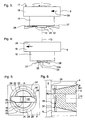
- 1 means a lock, 2 a door leaf of a safe door, 3 an opening in the door leaf 2, 4 a closure cap placed on the outside of the door leaf 2 and 5 a securing element.
- a recess in the closure cap 4 forms between the closure cap 4 and the door leaf 2 a cylindrical cavity 6, which has a cylindrical recess 8 via a passage 7 the front surface 9 of the closure cap 4 is connected.
- a housing 10 of the lock 1 has Keyhole 11, in order to operate the lock 1 a key, not shown here introduce.
- the keyhole 11, the cavity 6, the passage 7 and the cylindrical recess 8 have a common axis 12.
- the cavity 6 and the recess 8 have the same Inner radius R1, while the passage 7 has a smaller inner radius R2.
- the body of the securing element 5 is advantageously composed of two coaxial cylinders 15, 16, the first cylinder 15 with the smaller radius with little play in the passage 7 and the second cylinder 16 with the larger radius fit into the recess 8 with little play.
- the height of the second cylinder 16 is advantageously dimensioned such that when the second cylinder 16 is on the paragraph 13 sits, the top 17 of the second cylinder 16 is flush with the front surface 9.
- the Transition between the two cylinders 15, 16 forms an annular surface 18 parallel to Top 17
- the second cylinder 16 has a blind hole 19 with a weakly elliptical one in the upper side 17 Cross section on which a correspondingly shaped pin 20 of an assembly key 21 can accommodate.
- Embodiments of the assembly key 21 and the blind hole 19 are mentioned in the above Patent application EP-A 754'828 described.
- the lower end of the securing element 5 has at least one symmetrical to the axis 12 trained locking spring 22, the arms of which over the lateral surface of the first cylinder 15 protrude and measured from the axis 12 are slightly smaller than the inner radius R1 Indentation 8. To secure the lock, the securing element 5 with the locking springs 22 is advanced pushed into the recess 8.
- the lock 1 is arranged on the inside of the door leaf 2 and can easily be opened when the safe door is open to be replaced.
- FIG. 2 shows the top view of the front surface 9 of the closure cap 4.
- a passage for the Arms of the locking spring 22 (Figure 1) has the passage 7 slot-shaped extensions 23, 24 from Inner radius R2 to the inner radius R1, which the cavity 6 ( Figure 1) with the recess 8th connect and are so wide that when inserting the securing element 5 ( Figure 1) the arms of Locking spring 22 at the lower end of the securing element 5 through the slot-shaped Extensions 23, 24 penetrate into the cavity 6.
- the securing element 5 are therefore fully inserted into the recess 8 until the Annular surface 18 ( Figure 1) rests on the shoulder 13 and the surface 17 ( Figure 1) flush with the Front surface is 9.
- FIG. 3 shows a view of the securing element 5 with the locking spring 22.
- the first cylinder 15 has, for example, claws 25 arranged symmetrically to the axis 12 on the free top surface, with which the locking spring 22 is held against rotation and laterally. Is conceivable also a mandrel penetrating the locking spring 22 with a square cross section, which in the Locking spring 22 engages positively and is riveted, screwed or otherwise attached.
- the example of the securing element 5 shown here is set up for clockwise rotation, i.e. it will rotated clockwise (direction of an arrow 26 on the outer surface of the cylinder 16) when one looks at the top 17.
- the locking spring 22 has two arms with the skids 27, 28, which the Securing element 5 in the cap 4 ( Figure 1) can hold.
- the locking spring 22 is in the Area of the slideway 14 ( Figure 1) deformed to the skids 27, 28, the two in the Edges of the locking spring 22 lying in the direction of rotation are bent away from the first cylinder 15. In the drawing of Figure 3, the front edge on the right and the rear edge on the left of the locking spring 22 as pulled up on a sled.
- the securing element 5 is after a clockwise rotation of 90 ° about the axis 12 shown.
- the new position of the arrow 26 on the lateral surface of the second cylinder 16 is intended to do this suggest.
- the formation of the skids 27, 28 is now clearly recognizable.
- the skids 27, 28 enable the arresting spring 22 to run onto the slideway 14.
- two thinner spring plates, the Locking spring 22 and a flat spring leaf 22a used, the locking spring 22 with the Skids 27, 28 between the spring leaf 22a and the free circular area of the first cylinder 15 is arranged.
- the claws 25 hold the locking spring 22 and the spring leaf 22a together and prevent the two spring leaves from twisting relative to the first cylinder 15.
- FIG. 5 shows the view from the cavity 6 (FIG. 1) onto the securing element 5 used ( Figure 1) shown.
- the slideway 14 (FIG. 1) is divided into four flat sections 29, 29 ', 31, 31', of which the plane with the opposite sections 29, 29 'and 31, 31' from the front 9 ( Figure 1) measured have a different distance.
- the bottom of the two locking fields 30, 30 ' are at least deeper than that by the thickness of the locking spring 22 Level of the first sections 29, 29 'worked into the material of the closure cap 4.
- locking spring 22 is inserted into a groove 32 in first cylinder 15 and secured with a screw 33.
- the locking spring 22 aligned along the line A - A '. After clockwise rotation of the securing element 5 by 90 ° Skids 27, 28 snapped into the locking areas 30, 30 ', so that the securing element 5 in the Cap 4 is anchored.
- the cross section A-A ' illustrates the design of the slideway 14 (FIG. 1).
- the plane of the grid 30 are parallel.
- the level of the rest area 30 is closest to the front side 9 and the plane of the second section 31 is farthest from the front 9.
- the securing element 5 here has the special shape of a truncated cone with the axis 12, which in a correspondingly shaped opening is inserted in the closure cap 4 of the door leaf 2 and extends from the front 9 to the cavity 6.
- the opening widens evenly from Inner radius R2 at the transition to cavity 6 to the value of inner radius R1 on the front 9.
- FIG. 7 shows the closure cap 4 in cross section with the securing element 5 used according to the embodiment of FIG. 1.
- the skids 27 ( Figure 1), 28 of the locking spring 22 through the extensions 23, 24 of the passage 7 ( Figure 1) pushed into the cavity 6.
- the sliding skid 28 via a leading edge 29a on the first section 29 'of the slideway 14, the locking spring 22 being tensioned.
- the skid 28 then slides on the first section 29 '.
- the locking spring 22 After completing the Clockwise rotation of 90 °, the locking spring 22 partially relaxes because the skid 28 on the deeper as the first section 29 'arranged bottom of the rest area 30' sinks. In this in FIG. 7 Drawn position, the securing element 5 is secured in the cap 4. When unlocking is to be turned in the same direction so that the skid 28 to the height of the second section 31 'is raised. This requires a much greater torque than when securing, because the locking spring 22 experiences a greater deflection (deflection). The skid 28 slides on the second section 31 'until reaching the extension 24.
- Figures 8 to 10 show the development of the lateral surface 36, 36 'of the passage 7 (Figure 1) the profile of the slideway 14 (FIG. 1) as a function of the angle of rotation ⁇ with the three important positions of the skids 27, 28 and illustrate the process of securing and unlocking the lock 1 ( Figure 1). Since the process is repeated after 360 °, these parts are dotted
- the securing element 5 (FIG. 7) is completely in the opening for securing Cap 4 ( Figure 7) inserted, the skids 27, 28 through the extensions 24, 23rd reach cavity 6 through it.
- the slide shape of the skids 27, 28 is selected so that it is a right turn, i.e. in the direction of a positive angle, easily through the drive-on edges 29a, 29b onto the first sections 29, 29 'are raised, the locking spring 22 ( Figure 7) under tension is set.
- a left turn i.e.
- FIG. 9 shows the situation of the skids 27, 28 with one in the closure cap 4 (FIG. 7) secured securing element 5 (Figure 7).
- the usual left turn to unlock the Securing element 5 is not possible because the skid ends 34, 34 'when trying a Turn to the left immediately at the vertical boundaries of the grid areas 30, 30 'and another Prevent left turn.
- To unlock the securing element 5 must necessarily continue be turned to the right.
- the skids 27, 28 must be level with the second sections 31, 31 ' can be raised, the locking spring 22 ( Figure 7) much stronger than in the process of securing is excited.
- the torque required for unlocking is therefore very high and wakes you up Unauthorized persons have the impression that the safety element 5 is unlocked in a different way.
- the closure cap 4 is on the door leaf 2 riveted.
- the height of the cylindrical cap 4 is 20 mm, the diameter of 75 mm.
- the inner radius R1 (FIG. 2) of the recess 8 and the inner radius R2 (FIG. 2) of the passage 7 have the values 23.0 mm and 15.3 mm.
- the paragraph 13 is lowered by 6.0 mm from the front panel 9.
- the plane of the first sections 29, 29 '(FIG. 8) of the slideway 14 is 13.2 mm from the front plate 9 removed, while the plane of the second sections 31, 31 'at 14.2 mm further from the front plate 9 is removed.
- the bottom of the latching fields 30, 30 ' is spaced 12.0 mm from the front plate 9.
- the second Cylinder 16 of the security element 5 has a play of 0.5 mm in the recess 8 and the first Cylinder 15 is 0.6 mm narrower in diameter than passage 7.
- the level of the locking spring in the relaxed state is 11 mm from the surface 17.
- the locking spring 22 in Figure 5 is 12 mm wide and measures 44 mm in length overall.
- the multi-arm locking springs 22 require a finer division the slideway 14 and an increase in the number of extensions 23, 24.
Claims (7)
- Dispositif pour obtenir sécuriser une serrure (1) contre l'accès non autorisé ou le vandalisme, avec un chapeau de fermeture (4) couvrant une ouverture de clé (11) ledit chapeau de fermeture lorsqu'il est monté forme une extension de l'ouverture de clé (11) et une cavité (6) qui communique via une ouverture (7, 8) avec une face frontale (9) du chapeau de fermeture (4) et reçoit un élément de sécurité (5) d'une forme ajustée qui couvre l'ouverture de clé (11), dispositif qui peut être bloqué en place dans un mouvement de rotation et qui en état d'insertion est fuselé en ce qui concerne la serrure (1), caractérisé en ce que l'élément de sécurité (5) sur son côté fuselé est disposé de telle sorte d'être assuré par au moins un ressort de blocage en forme de feuille (22, 22a) contre la torsion, en ce que les bras qui avancent sur le côté fuselé de l'élément de sécurité (5) du ressort de blocage (22) sont déformés pour former des patins (27; 28), en ce que l'ouverture (7) montre des élargissements en forme de rainure (23; 24) pour insérer le ressort de blocage (22, 22a) dans la cavité (6) et en ce qu'une glissière (14) formée dans le chapeau de fermeture (4), ouverte en direction de la cavité (6) et interrompue par les élargissements (23; 24), est formée de façon à ce que, après une rotation prédéterminée de l'élément de sécurité (5) inséré dans le chapeau de fermeture (4), les patins (27;28) sont élevés sur les premières sections (29; 29') sous pression du ressort de blocage (22, 22a) et maintiennent l'élément de sécurité (5) fixé sur l'ouverture alors qu'ils atteignent l'arrière de ladite ouverture (7).
- Dispositif selon la revendication 1, caractérisé en ce que la glissière (14) montre des champs d'engrènement (30, 30') placés à 180° conçus pour recevoir les patins (27, 28) après leurs rotations à un angle prédéterminé de rotation, et en ce que les champs d'engrènement (30, 30') sont formés de telle sorte que pour relâcher l'élément de sécurité (5), les patins (27, 28) crantés dans les champs d'engrènement (30; 30') peuvent se déplacer uniquement dans le même sens de rotation que lors du passage aux secondes sections (31, 31') de la glissière (14) aux élargissements (24; 23).
- Dispositif selon la revendication 2, caractérisé en ce que le ressort de blocage (22, 22a) montre sur les secondes sections (31; 31') une flexion plus grande que sur les premières sections (29; 29).
- Dispositif selon une des revendications 1 à 3, caractérisé en ce que le logement de l'élément de sécurité (5) inclut deux cylindres (15; 16) à des diamètres différents, le second cylindre (16) avec le plus gros diamètre ayant sur sa surface libre (17) au moins un trou borgne (19), pour la réception de chevilles (20) d'une forme adaptée à une clé de montage (21).
- Dispositif selon une des revendications 1 à 3, caractérisé en ce que le logement de l'élément de sécurité (5) est un cône tronqué, dont la surface en forme de cercle (17) avec laquelle le diamètre plus gros montre au moins un trou borgne (19) inséré dans l'élément de sécurité (5) pour loger les chevilles (20) d'une forme adaptée à une clé de montage (21).
- Dispositif selon une des revendications 1 à 5, caractérisé en ce que la surface externe (17) de l'élément de sécurité (5) inséré dans le chapeau de fermeture (4) est à niveau avec la face frontale (9) du chapeau de fermeture (4).
- Dispositif selon une des revendications 1 à 6, caractérisé en ce que le chapeau de fermeture (4) est intégré dans la porte battante (2)
Applications Claiming Priority (2)
| Application Number | Priority Date | Filing Date | Title |
|---|---|---|---|
| DE29715732U DE29715732U1 (de) | 1997-09-02 | 1997-09-02 | Anordnung zur Sicherung einer Schlüsselöffnung gegen unbefugten Zugriff oder Vandalismus |
| DE29715732U | 1997-09-02 |
Publications (3)
| Publication Number | Publication Date |
|---|---|
| EP0900899A2 EP0900899A2 (fr) | 1999-03-10 |
| EP0900899A3 EP0900899A3 (fr) | 1999-11-03 |
| EP0900899B1 true EP0900899B1 (fr) | 2003-04-09 |
Family
ID=8045425
Family Applications (1)
| Application Number | Title | Priority Date | Filing Date |
|---|---|---|---|
| EP98113977A Expired - Lifetime EP0900899B1 (fr) | 1997-09-02 | 1998-07-27 | Système de protection du canal de clé d'une serrure interdisant l'accès non-autorisé et le vandalisme |
Country Status (3)
| Country | Link |
|---|---|
| EP (1) | EP0900899B1 (fr) |
| AT (1) | ATE237057T1 (fr) |
| DE (2) | DE29715732U1 (fr) |
Families Citing this family (3)
| Publication number | Priority date | Publication date | Assignee | Title |
|---|---|---|---|---|
| EP2115707A1 (fr) | 1998-10-30 | 2009-11-11 | IPM International SA | Contenant de surete |
| FR2857047A1 (fr) * | 2003-07-01 | 2005-01-07 | Amonter | Dispositif de securisation d'un acces a une serrure |
| CN105750770B (zh) * | 2016-04-12 | 2018-03-20 | 中车青岛四方机车车辆股份有限公司 | 新型的孔防护装置及其使用方法 |
Family Cites Families (2)
| Publication number | Priority date | Publication date | Assignee | Title |
|---|---|---|---|---|
| US5044679A (en) * | 1990-02-26 | 1991-09-03 | Norco, Inc. | Latch construction |
| DE59601857D1 (de) * | 1995-07-18 | 1999-06-17 | Landis & Gyr Tech Innovat | Anordnung zur Sicherung einer Schlüsselöffnung eines Schlosses gegen unbefugten Zugriff oder Vandalismus |
-
1997
- 1997-09-02 DE DE29715732U patent/DE29715732U1/de not_active Expired - Lifetime
-
1998
- 1998-07-27 DE DE59807817T patent/DE59807817D1/de not_active Expired - Fee Related
- 1998-07-27 EP EP98113977A patent/EP0900899B1/fr not_active Expired - Lifetime
- 1998-07-27 AT AT98113977T patent/ATE237057T1/de not_active IP Right Cessation
Also Published As
| Publication number | Publication date |
|---|---|
| DE29715732U1 (de) | 1999-01-14 |
| ATE237057T1 (de) | 2003-04-15 |
| DE59807817D1 (de) | 2003-05-15 |
| EP0900899A2 (fr) | 1999-03-10 |
| EP0900899A3 (fr) | 1999-11-03 |
Similar Documents
| Publication | Publication Date | Title |
|---|---|---|
| DE2618674A1 (de) | Tuerschloss | |
| CH620266A5 (fr) | ||
| DE202008000911U1 (de) | Zylinderschloß mit Plättchenzuhaltungen und Schlüssel für das Schloß | |
| DE1678661A1 (de) | Sicherheitsschloss | |
| EP1118071A1 (fr) | Element a accrocher comportant un arceau verrouillable | |
| CH644179A5 (en) | Locking system | |
| EP0900899B1 (fr) | Système de protection du canal de clé d'une serrure interdisant l'accès non-autorisé et le vandalisme | |
| EP0712980B1 (fr) | Serrure cylindrique avec noyau cylindrique et boítier cylindrique | |
| EP2113624B1 (fr) | Dispositif de fixation de porte ou de fenêtre | |
| EP0585735B1 (fr) | Serrure de fixation pour cylindre d'un verrou de sécurité | |
| DE102007014900A1 (de) | Schließvorrichtung mit einem Schlüssel und einem Schließzylinder | |
| DE8534096U1 (de) | Zylinderschloß mit einer Nachschließsicherung | |
| DE3642253A1 (de) | Abschliessbarer fenstergriff | |
| DE2622961A1 (de) | Schloss mit mindestens einem beim einfuehren des schluessels ausweichenden schliessorgan und verfahren zur erstellung dieses schlosses | |
| DE19609846C2 (de) | Gleitblech und elektrischer Türöffner mit einem solchen Gleitblech | |
| DE4222157C2 (de) | Schloß mit durch Münzeinwurf entriegelbaren Sperrteilen | |
| DE19507481C1 (de) | Abschließbarer Fenstergriff | |
| DE4226721C2 (de) | Kernschutz | |
| DE3305209C2 (fr) | ||
| DE10203994B4 (de) | Schließvorrichtung | |
| EP0620340A2 (fr) | Serrure cylindrique | |
| CH628387A5 (en) | Locking system | |
| DE19507575A1 (de) | Verriegelungseinrichtung | |
| EP0756052A1 (fr) | Serrure cylindrique à goupilles et une clé pour une serrure à goupilles | |
| EP0861955B1 (fr) | Bouton de fenêtre verrouiable |
Legal Events
| Date | Code | Title | Description |
|---|---|---|---|
| PUAI | Public reference made under article 153(3) epc to a published international application that has entered the european phase |
Free format text: ORIGINAL CODE: 0009012 |
|
| AK | Designated contracting states |
Kind code of ref document: A2 Designated state(s): AT CH DE DK ES FR GB LI |
|
| AX | Request for extension of the european patent |
Free format text: AL;LT;LV;MK;RO;SI |
|
| PUAL | Search report despatched |
Free format text: ORIGINAL CODE: 0009013 |
|
| AK | Designated contracting states |
Kind code of ref document: A3 Designated state(s): AT BE CH CY DE DK ES FI FR GB GR IE IT LI LU MC NL PT SE |
|
| AX | Request for extension of the european patent |
Free format text: AL;LT;LV;MK;RO;SI |
|
| RAP1 | Party data changed (applicant data changed or rights of an application transferred) |
Owner name: IP-TPG HOLDCO S.A.R.L. |
|
| 17P | Request for examination filed |
Effective date: 20000503 |
|
| AKX | Designation fees paid |
Free format text: AT CH DE DK ES FR GB LI |
|
| 19U | Interruption of proceedings before grant |
Effective date: 20010206 |
|
| GRAG | Despatch of communication of intention to grant |
Free format text: ORIGINAL CODE: EPIDOS AGRA |
|
| 17Q | First examination report despatched |
Effective date: 20010522 |
|
| 19W | Proceedings resumed before grant after interruption of proceedings |
Effective date: 20020904 |
|
| GRAG | Despatch of communication of intention to grant |
Free format text: ORIGINAL CODE: EPIDOS AGRA |
|
| GRAH | Despatch of communication of intention to grant a patent |
Free format text: ORIGINAL CODE: EPIDOS IGRA |
|
| RAP1 | Party data changed (applicant data changed or rights of an application transferred) |
Owner name: IPM INTERNATIONAL SA |
|
| GRAH | Despatch of communication of intention to grant a patent |
Free format text: ORIGINAL CODE: EPIDOS IGRA |
|
| GRAG | Despatch of communication of intention to grant |
Free format text: ORIGINAL CODE: EPIDOS AGRA |
|
| GRAA | (expected) grant |
Free format text: ORIGINAL CODE: 0009210 |
|
| AK | Designated contracting states |
Designated state(s): AT CH DE DK ES FR GB LI |
|
| REG | Reference to a national code |
Ref country code: GB Ref legal event code: FG4D Free format text: NOT ENGLISH |
|
| REG | Reference to a national code |
Ref country code: CH Ref legal event code: EP |
|
| REG | Reference to a national code |
Ref country code: CH Ref legal event code: NV Representative=s name: LEMAN CONSULTING S.A. |
|
| PG25 | Lapsed in a contracting state [announced via postgrant information from national office to epo] |
Ref country code: DK Free format text: LAPSE BECAUSE OF FAILURE TO SUBMIT A TRANSLATION OF THE DESCRIPTION OR TO PAY THE FEE WITHIN THE PRESCRIBED TIME-LIMIT Effective date: 20030709 |
|
| PG25 | Lapsed in a contracting state [announced via postgrant information from national office to epo] |
Ref country code: AT Free format text: LAPSE BECAUSE OF NON-PAYMENT OF DUE FEES Effective date: 20030727 |
|
| GBT | Gb: translation of ep patent filed (gb section 77(6)(a)/1977) |
Effective date: 20030715 |
|
| PG25 | Lapsed in a contracting state [announced via postgrant information from national office to epo] |
Ref country code: ES Free format text: LAPSE BECAUSE OF FAILURE TO SUBMIT A TRANSLATION OF THE DESCRIPTION OR TO PAY THE FEE WITHIN THE PRESCRIBED TIME-LIMIT Effective date: 20031030 |
|
| PLBE | No opposition filed within time limit |
Free format text: ORIGINAL CODE: 0009261 |
|
| STAA | Information on the status of an ep patent application or granted ep patent |
Free format text: STATUS: NO OPPOSITION FILED WITHIN TIME LIMIT |
|
| ET | Fr: translation filed | ||
| 26N | No opposition filed |
Effective date: 20040112 |
|
| REG | Reference to a national code |
Ref country code: CH Ref legal event code: PCAR Free format text: LEMAN CONSULTING S.A.;CHEMIN DE PRECOSSY 31;1260 NYON (CH) |
|
| PGFP | Annual fee paid to national office [announced via postgrant information from national office to epo] |
Ref country code: FR Payment date: 20090716 Year of fee payment: 12 |
|
| PGFP | Annual fee paid to national office [announced via postgrant information from national office to epo] |
Ref country code: GB Payment date: 20090720 Year of fee payment: 12 Ref country code: DE Payment date: 20090722 Year of fee payment: 12 Ref country code: CH Payment date: 20090715 Year of fee payment: 12 |
|
| REG | Reference to a national code |
Ref country code: CH Ref legal event code: PL |
|
| GBPC | Gb: european patent ceased through non-payment of renewal fee |
Effective date: 20100727 |
|
| REG | Reference to a national code |
Ref country code: FR Ref legal event code: ST Effective date: 20110331 |
|
| PG25 | Lapsed in a contracting state [announced via postgrant information from national office to epo] |
Ref country code: DE Free format text: LAPSE BECAUSE OF NON-PAYMENT OF DUE FEES Effective date: 20110201 Ref country code: LI Free format text: LAPSE BECAUSE OF NON-PAYMENT OF DUE FEES Effective date: 20100731 Ref country code: CH Free format text: LAPSE BECAUSE OF NON-PAYMENT OF DUE FEES Effective date: 20100731 |
|
| REG | Reference to a national code |
Ref country code: DE Ref legal event code: R119 Ref document number: 59807817 Country of ref document: DE Effective date: 20110201 |
|
| PG25 | Lapsed in a contracting state [announced via postgrant information from national office to epo] |
Ref country code: FR Free format text: LAPSE BECAUSE OF NON-PAYMENT OF DUE FEES Effective date: 20100802 |
|
| PG25 | Lapsed in a contracting state [announced via postgrant information from national office to epo] |
Ref country code: GB Free format text: LAPSE BECAUSE OF NON-PAYMENT OF DUE FEES Effective date: 20100727 |