EP0900899B1 - Device for protection of a key hole against unauthorised access and vandalism - Google Patents
Device for protection of a key hole against unauthorised access and vandalism Download PDFInfo
- Publication number
- EP0900899B1 EP0900899B1 EP98113977A EP98113977A EP0900899B1 EP 0900899 B1 EP0900899 B1 EP 0900899B1 EP 98113977 A EP98113977 A EP 98113977A EP 98113977 A EP98113977 A EP 98113977A EP 0900899 B1 EP0900899 B1 EP 0900899B1
- Authority
- EP
- European Patent Office
- Prior art keywords
- safety element
- locking cap
- sections
- skids
- rotation
- Prior art date
- Legal status (The legal status is an assumption and is not a legal conclusion. Google has not performed a legal analysis and makes no representation as to the accuracy of the status listed.)
- Expired - Lifetime
Links
Images


Classifications
-
- E—FIXED CONSTRUCTIONS
- E05—LOCKS; KEYS; WINDOW OR DOOR FITTINGS; SAFES
- E05B—LOCKS; ACCESSORIES THEREFOR; HANDCUFFS
- E05B17/00—Accessories in connection with locks
- E05B17/14—Closures or guards for keyholes
-
- E—FIXED CONSTRUCTIONS
- E05—LOCKS; KEYS; WINDOW OR DOOR FITTINGS; SAFES
- E05B—LOCKS; ACCESSORIES THEREFOR; HANDCUFFS
- E05B35/00—Locks for use with special keys or a plurality of keys ; keys therefor
- E05B35/008—Locks for use with special keys or a plurality of keys ; keys therefor for simple tool-like keys
Definitions
- the invention relates to an arrangement for securing a key opening Lock against unauthorized access or vandalism according to the preamble of claim 1.
- the arrangement is used for locking devices of all kinds, which have a special one Protection against unauthorized access and especially against vandalism, for example from cash cassettes in a variety of different ways Cash dispensers arranged in vending machines, particularly for safes from coin-operated telephones - Machines.
- a Locking cap is arranged in front of a key opening of a lock and allows one through a cylindrical opening of the cap through the key To operate the lock.
- a suitable one in the cylindrical opening of the cap Lock cylinder is at one end with a locking pin arranged transversely to the cylinder axis equipped.
- the security cylinder is used to secure the lock in advance with the locking pin inserted the opening of the cap, the locking pin through a slit-shaped Recess of a plate arranged in the depth of the opening of the closure cap is pushed. With a rotation of the security cylinder around its own axis with the help a key, the locking pin engages behind the plate with the slot-shaped recess and engages in locking springs arranged behind the plate.
- This device has the disadvantage that the torque for locking and unlocking is practical is the same size, so that with a locking cap that is easy to secure, even from The lock can be unlocked by unauthorized persons.
- the invention has for its object to a cap for securing a lock create in which the torque when unlocking is several times greater than when locking.
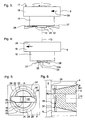
- 1 means a lock, 2 a door leaf of a safe door, 3 an opening in the door leaf 2, 4 a closure cap placed on the outside of the door leaf 2 and 5 a securing element.
- a recess in the closure cap 4 forms between the closure cap 4 and the door leaf 2 a cylindrical cavity 6, which has a cylindrical recess 8 via a passage 7 the front surface 9 of the closure cap 4 is connected.
- a housing 10 of the lock 1 has Keyhole 11, in order to operate the lock 1 a key, not shown here introduce.
- the keyhole 11, the cavity 6, the passage 7 and the cylindrical recess 8 have a common axis 12.
- the cavity 6 and the recess 8 have the same Inner radius R1, while the passage 7 has a smaller inner radius R2.
- the body of the securing element 5 is advantageously composed of two coaxial cylinders 15, 16, the first cylinder 15 with the smaller radius with little play in the passage 7 and the second cylinder 16 with the larger radius fit into the recess 8 with little play.
- the height of the second cylinder 16 is advantageously dimensioned such that when the second cylinder 16 is on the paragraph 13 sits, the top 17 of the second cylinder 16 is flush with the front surface 9.
- the Transition between the two cylinders 15, 16 forms an annular surface 18 parallel to Top 17
- the second cylinder 16 has a blind hole 19 with a weakly elliptical one in the upper side 17 Cross section on which a correspondingly shaped pin 20 of an assembly key 21 can accommodate.
- Embodiments of the assembly key 21 and the blind hole 19 are mentioned in the above Patent application EP-A 754'828 described.
- the lower end of the securing element 5 has at least one symmetrical to the axis 12 trained locking spring 22, the arms of which over the lateral surface of the first cylinder 15 protrude and measured from the axis 12 are slightly smaller than the inner radius R1 Indentation 8. To secure the lock, the securing element 5 with the locking springs 22 is advanced pushed into the recess 8.
- the lock 1 is arranged on the inside of the door leaf 2 and can easily be opened when the safe door is open to be replaced.
- FIG. 2 shows the top view of the front surface 9 of the closure cap 4.
- a passage for the Arms of the locking spring 22 (Figure 1) has the passage 7 slot-shaped extensions 23, 24 from Inner radius R2 to the inner radius R1, which the cavity 6 ( Figure 1) with the recess 8th connect and are so wide that when inserting the securing element 5 ( Figure 1) the arms of Locking spring 22 at the lower end of the securing element 5 through the slot-shaped Extensions 23, 24 penetrate into the cavity 6.
- the securing element 5 are therefore fully inserted into the recess 8 until the Annular surface 18 ( Figure 1) rests on the shoulder 13 and the surface 17 ( Figure 1) flush with the Front surface is 9.
- FIG. 3 shows a view of the securing element 5 with the locking spring 22.
- the first cylinder 15 has, for example, claws 25 arranged symmetrically to the axis 12 on the free top surface, with which the locking spring 22 is held against rotation and laterally. Is conceivable also a mandrel penetrating the locking spring 22 with a square cross section, which in the Locking spring 22 engages positively and is riveted, screwed or otherwise attached.
- the example of the securing element 5 shown here is set up for clockwise rotation, i.e. it will rotated clockwise (direction of an arrow 26 on the outer surface of the cylinder 16) when one looks at the top 17.
- the locking spring 22 has two arms with the skids 27, 28, which the Securing element 5 in the cap 4 ( Figure 1) can hold.
- the locking spring 22 is in the Area of the slideway 14 ( Figure 1) deformed to the skids 27, 28, the two in the Edges of the locking spring 22 lying in the direction of rotation are bent away from the first cylinder 15. In the drawing of Figure 3, the front edge on the right and the rear edge on the left of the locking spring 22 as pulled up on a sled.
- the securing element 5 is after a clockwise rotation of 90 ° about the axis 12 shown.
- the new position of the arrow 26 on the lateral surface of the second cylinder 16 is intended to do this suggest.
- the formation of the skids 27, 28 is now clearly recognizable.
- the skids 27, 28 enable the arresting spring 22 to run onto the slideway 14.
- two thinner spring plates, the Locking spring 22 and a flat spring leaf 22a used, the locking spring 22 with the Skids 27, 28 between the spring leaf 22a and the free circular area of the first cylinder 15 is arranged.
- the claws 25 hold the locking spring 22 and the spring leaf 22a together and prevent the two spring leaves from twisting relative to the first cylinder 15.
- FIG. 5 shows the view from the cavity 6 (FIG. 1) onto the securing element 5 used ( Figure 1) shown.
- the slideway 14 (FIG. 1) is divided into four flat sections 29, 29 ', 31, 31', of which the plane with the opposite sections 29, 29 'and 31, 31' from the front 9 ( Figure 1) measured have a different distance.
- the bottom of the two locking fields 30, 30 ' are at least deeper than that by the thickness of the locking spring 22 Level of the first sections 29, 29 'worked into the material of the closure cap 4.
- locking spring 22 is inserted into a groove 32 in first cylinder 15 and secured with a screw 33.
- the locking spring 22 aligned along the line A - A '. After clockwise rotation of the securing element 5 by 90 ° Skids 27, 28 snapped into the locking areas 30, 30 ', so that the securing element 5 in the Cap 4 is anchored.
- the cross section A-A ' illustrates the design of the slideway 14 (FIG. 1).
- the plane of the grid 30 are parallel.
- the level of the rest area 30 is closest to the front side 9 and the plane of the second section 31 is farthest from the front 9.
- the securing element 5 here has the special shape of a truncated cone with the axis 12, which in a correspondingly shaped opening is inserted in the closure cap 4 of the door leaf 2 and extends from the front 9 to the cavity 6.
- the opening widens evenly from Inner radius R2 at the transition to cavity 6 to the value of inner radius R1 on the front 9.
- FIG. 7 shows the closure cap 4 in cross section with the securing element 5 used according to the embodiment of FIG. 1.
- the skids 27 ( Figure 1), 28 of the locking spring 22 through the extensions 23, 24 of the passage 7 ( Figure 1) pushed into the cavity 6.
- the sliding skid 28 via a leading edge 29a on the first section 29 'of the slideway 14, the locking spring 22 being tensioned.
- the skid 28 then slides on the first section 29 '.
- the locking spring 22 After completing the Clockwise rotation of 90 °, the locking spring 22 partially relaxes because the skid 28 on the deeper as the first section 29 'arranged bottom of the rest area 30' sinks. In this in FIG. 7 Drawn position, the securing element 5 is secured in the cap 4. When unlocking is to be turned in the same direction so that the skid 28 to the height of the second section 31 'is raised. This requires a much greater torque than when securing, because the locking spring 22 experiences a greater deflection (deflection). The skid 28 slides on the second section 31 'until reaching the extension 24.
- Figures 8 to 10 show the development of the lateral surface 36, 36 'of the passage 7 (Figure 1) the profile of the slideway 14 (FIG. 1) as a function of the angle of rotation ⁇ with the three important positions of the skids 27, 28 and illustrate the process of securing and unlocking the lock 1 ( Figure 1). Since the process is repeated after 360 °, these parts are dotted
- the securing element 5 (FIG. 7) is completely in the opening for securing Cap 4 ( Figure 7) inserted, the skids 27, 28 through the extensions 24, 23rd reach cavity 6 through it.
- the slide shape of the skids 27, 28 is selected so that it is a right turn, i.e. in the direction of a positive angle, easily through the drive-on edges 29a, 29b onto the first sections 29, 29 'are raised, the locking spring 22 ( Figure 7) under tension is set.
- a left turn i.e.
- FIG. 9 shows the situation of the skids 27, 28 with one in the closure cap 4 (FIG. 7) secured securing element 5 (Figure 7).
- the usual left turn to unlock the Securing element 5 is not possible because the skid ends 34, 34 'when trying a Turn to the left immediately at the vertical boundaries of the grid areas 30, 30 'and another Prevent left turn.
- To unlock the securing element 5 must necessarily continue be turned to the right.
- the skids 27, 28 must be level with the second sections 31, 31 ' can be raised, the locking spring 22 ( Figure 7) much stronger than in the process of securing is excited.
- the torque required for unlocking is therefore very high and wakes you up Unauthorized persons have the impression that the safety element 5 is unlocked in a different way.
- the closure cap 4 is on the door leaf 2 riveted.
- the height of the cylindrical cap 4 is 20 mm, the diameter of 75 mm.
- the inner radius R1 (FIG. 2) of the recess 8 and the inner radius R2 (FIG. 2) of the passage 7 have the values 23.0 mm and 15.3 mm.
- the paragraph 13 is lowered by 6.0 mm from the front panel 9.
- the plane of the first sections 29, 29 '(FIG. 8) of the slideway 14 is 13.2 mm from the front plate 9 removed, while the plane of the second sections 31, 31 'at 14.2 mm further from the front plate 9 is removed.
- the bottom of the latching fields 30, 30 ' is spaced 12.0 mm from the front plate 9.
- the second Cylinder 16 of the security element 5 has a play of 0.5 mm in the recess 8 and the first Cylinder 15 is 0.6 mm narrower in diameter than passage 7.
- the level of the locking spring in the relaxed state is 11 mm from the surface 17.
- the locking spring 22 in Figure 5 is 12 mm wide and measures 44 mm in length overall.
- the multi-arm locking springs 22 require a finer division the slideway 14 and an increase in the number of extensions 23, 24.
Abstract
Description
Die Erfindung bezieht sich auf eine Anordnung zur Sicherung einer Schlüsselöffnung eines
Schlosses gegen unbefugten Zugriff oder Vandalismus gemäss dem Oberbegriff des Anspruchs 1.The invention relates to an arrangement for securing a key opening
Lock against unauthorized access or vandalism according to the preamble of
Die Anordnung wird verwendet für Schliesseinrichtungen aller Art, welche eines besonderen Schutzes gegen unbefugten Zugriff und ganz besonders gegen Vandalismus bedürfen, beispielsweise von Geldkassetten von in einer Öffentlichkeit aufgestellten und in unterschiedlichsten Verkaufsautomaten angeordneten Kassiereinheiten, insbesondere bei Tresoren von Münztelephon - Automaten.The arrangement is used for locking devices of all kinds, which have a special one Protection against unauthorized access and especially against vandalism, for example from cash cassettes in a variety of different ways Cash dispensers arranged in vending machines, particularly for safes from coin-operated telephones - Machines.
Eine Anordnung der eingangs genannten Art ist aus der EP-A 754'828 bekannt. Eine Verschlusskappe ist vor einer Schlüsselöffnung eines Schlosses angeordnet und erlaubt mit einem durch eine zylinderförmige Oeffnung der Verschlusskappe hindurch gesteckten Schlüssel das Schloss zu betätigen. Ein in die zylinderförmige Oeffnung der Verschlusskappe passender Sicherungszylinder ist an einem Ende mit einem quer zur Zylinderachse angeordneten Arretierstift ausgerüstet. Der Sicherungszylinder wird zum Sichern des Schlosses mit dem Arretierstift voraus in die Oeffnung der Verschlusskappe eingeführt, wobei der Arretierstift durch eine schlitzförmigen Ausnehmung einer in der Tiefe der Oeffnung der Verschlusskappe angeordneten Platte hindurch geschoben wird. Bei einer Drehbewegung des Sicherungszylinders um seine eigene Achse mit Hilfe eines Schlüssels hintergreift der Arretierstift die Platte mit der schlitzförmigen Ausnehmung und rastet in hinter der Platte angeordneten Arretierfedern ein.An arrangement of the type mentioned is known from EP-A 754'828. A Locking cap is arranged in front of a key opening of a lock and allows one through a cylindrical opening of the cap through the key To operate the lock. A suitable one in the cylindrical opening of the cap Lock cylinder is at one end with a locking pin arranged transversely to the cylinder axis equipped. The security cylinder is used to secure the lock in advance with the locking pin inserted the opening of the cap, the locking pin through a slit-shaped Recess of a plate arranged in the depth of the opening of the closure cap is pushed. With a rotation of the security cylinder around its own axis with the help a key, the locking pin engages behind the plate with the slot-shaped recess and engages in locking springs arranged behind the plate.
Diese Vorrichtung hat den Nachteil, dass das Drehmoment zum Sichern und Entsichern praktisch gleich gross ist, so dass mit einer beim Sichern leicht gängigen Verschlusskappe auch von Unbefugten das Schloss entsichert werden kann.This device has the disadvantage that the torque for locking and unlocking is practical is the same size, so that with a locking cap that is easy to secure, even from The lock can be unlocked by unauthorized persons.
Der Erfindung liegt die Aufgabe zugrunde, eine Verschlusskappe zum Sichern eines Schlosses zu schaffen, bei der das Drehmoment beim Entsichern ein mehrfaches grösser ist als beim Sichern.The invention has for its object to a cap for securing a lock create in which the torque when unlocking is several times greater than when locking.
Die genannte Aufgabe wird erfindungsgemäss durch die im Kennzeichen des Anspruchs 1 angegebenen
Merkmale gelöst. Vorteilhafte Ausgestaltungen der Erfindung ergeben sich aus den abhängigen
Ansprüchen.According to the invention, this object is achieved by the features specified in the characterizing part of
Ein Ausführungsbeispiel der Erfindung ist in den Zeichnungen dargestellt und wird im folgenden näher beschrieben.An embodiment of the invention is shown in the drawings and will be described in more detail below described.
Es zeigen:
Figur 1- einen Querschnitt durch eine Tür mit Schloss und Verschlusskappe sowie mit einem nicht eingesetzten Sicherungselement,
Figur 2- eine Frontansicht auf die Verschlusskappe ohne eingesetztes Sicherungs element,
Figur 3- das Sicherungselement,
Figur 4- das Sicherungselement um 90° um seine Achse gedreht,
Figur 5- das Sicherungselement in der Verschlusskappe,
Figur 6- eine andere Form des Sicherungselements,
Figur 7- einen Querschnitt durch die Verschlusskappe mit dem eingesetzten Sicherungselement,
Figur 8- eine Abwicklung einer Gleitbahn mit Gleitkufen in Stellung 0°
Figur 9- wie
Figur 8, aber mit Gleitkufen in Stellung 90° und Figur 10- wie
Figur 8, aber mit Gleitkufen in Stellung 180°.
- Figure 1
- a cross section through a door with lock and locking cap and with a security element not used,
- Figure 2
- a front view of the closure cap without the securing element inserted,
- Figure 3
- the securing element,
- Figure 4
- the securing element is rotated by 90 ° about its axis,
- Figure 5
- the securing element in the sealing cap,
- Figure 6
- another form of securing element,
- Figure 7
- a cross section through the cap with the security element used,
- Figure 8
- a development of a slide with skids in position 0 °
- Figure 9
- like Figure 8, but with skids in position 90 ° and
- Figure 10
- like Figure 8, but with skids in position 180 °.
In der Figur 1 bedeutet 1 ein Schloss, 2 ein Türblatt einer Tresortüre, 3 eine Oeffnung im Türblatt 2, 4
eine auf der Aussenseite des Türblatts 2 aufgesetzte Verschlusskappe und 5 ein Sicherungselement.
Zwischen der Verschlusskappe 4 und dem Türblatt 2 bildet eine Ausnehmung in der Verschlusskappe 4
einen zylindrischen Hohlraum 6, der über einen Durchgang 7 mit einer zylindrischen Vertiefung 8 auf
der Frontfläche 9 der Verschlusskappe 4 in Verbindung steht. Ein Gehäuse 10 des Schlosses 1 weist ein
Schlüsselloch 11 auf, um zum Betätigen des Schlosses 1 einen hier nicht gezeigten Schlüssel
einzuführen. Das Schlüsselloch 11, der Hohlraum 6, der Durchgang 7 und die zylindrische Vertiefung 8
besitzen eine gemeinsame Achse 12. Der Hohlraum 6 und die Vertiefung 8 weisen den gleichen
Innenradius R1 auf, während der Durchgang 7 einen kleineren Innenradius R2 aufweist. Der Uebergang
von der Vertiefung 8 zum Durchgang 7 bildet einen Absatz 13 parallel zur Frontfläche 9. Die
Erweiterung vom Durchgang 7 zum Hohlraum 6 dient als Gleitbahn 14, ebenfalls im wesentlichen
parallel zur Frontfläche 9. Die Oberflächen des Absatzes 13 und der Gleitbahn 14 sind geglättet. Wie in
der Patentanmeldung EP-A 754'828 beschrieben, ist die Verschlusskappe 4 auf das Türblatt 2 aufgesetzt
und vernietet oder, bei genügender Stärke des Türblatts 2, direkt in das Türblatt 2 integriert.In FIG. 1, 1 means a lock, 2 a door leaf of a safe door, 3 an opening in the
Der Körper des Sicherungselements 5 ist mit Vorteil aus zwei koaxialen Zylindern 15, 16 zusammengesetzt,
wobei der erste Zylinder 15 mit dem kleineren Radius mit geringem Spiel in den Durchgang 7
und der zweite Zylinder 16 mit dem grösseren Radius mit geringem Spiel in die Vertiefung 8 passen. Die
Höhe des zweiten Zylinders 16 ist mit Vorteil derart bemessen, dass, wenn der zweite Zylinder 16 auf
dem Absatz 13 aufsitzt, die Oberseite 17 des zweiten Zylinders 16 bündig mit der Frontfläche 9 ist. Der
Uebergang zwischen den beiden Zylindern 15, 16 bildet eine Kreisringfläche 18 parallel zur
Oberseite 17 The body of the
Der zweite Zylinder 16 weist in der Oberseite 17 ein Sackloch 19 mit einem schwach elliptischen
Querschnitt auf, das ein entsprechend geformter Zapfen 20 eines Montageschlüssels 21 aufnehmen kann.
Ausgestaltungen des Montageschlüssels 21 und des Sacklochs 19 sind in der eingangs genannten
Patentanmeldung EP-A 754'828 beschrieben.The
Das untere Ende des Sicherungselements 5 weist wenigstens eine symmetrisch zur Achse 12
ausgebildete Arretierfeder 22 auf, deren Arme über die Mantelfläche des ersten Zylinders 15
hinausragen und von der Achse 12 aus gemessen etwas kleiner sind als der Innenradius R1 der
Vertiefung 8. Zum Sichern des Schlosses wird das Sicherungselement 5 mit den Arretierfedern 22 voran
in die Vertiefung 8 geschoben.The lower end of the securing
Das Schloss 1 ist auf der Innenseite des Türblatts 2 angeordnet und kann bei geöffneter Tresortüre leicht
ausgewechselt werden.The
Die Figur 2 zeigt die Draufsicht auf die Frontfläche 9 der Verschlusskappe 4. Als Durchlass für die
Arme der Arretierfeder 22 (Figur 1) weist der Durchgang 7 schlitzförmige Erweiterungen 23, 24 vom
Innenradius R2 bis zum Innenradius R1 auf, die den Hohlraum 6 (Figur 1) mit der Vertiefung 8
verbinden und so breit sind, dass beim Einschieben des Sicherungselements 5 (Figur 1) die Arme der
Arretierfeder 22 am unteren Ende des Sicherungselements 5 durch die schlitzförmigen
Erweiterungen 23, 24 hindurch in den Hohlraum 6 vordringen. Zum Sichern des Schlüssellochs 11 kann
das Sicherungselement 5 daher vollständig in die Vertiefung 8 eingeschoben werden, bis die
Kreisringfläche 18 (Figur 1) auf dem Absatz 13 aufliegt und die Oberfläche 17 (Figur 1) bündig mit der
Frontfläche 9 ist.FIG. 2 shows the top view of the
Die Figur 3 zeigt eine Ansicht des Sicherungselements 5 mit der Arretierfeder 22. Der erste Zylinder 15
weist beispielsweise auf der freien Deckfläche symmetrisch zur Achse 12 angeordnete Klauen 25 auf,
mit denen die Arretierfeder 22 seitlich und diese übergreifend verdrehsicher gehalten wird. Denkbar ist
auch ein die Arretierfeder 22 durchdringender Dorn mit einem quadratischen Querschnitt, der in die
Arretierfeder 22 formschlüssig eingreift und mit ihr vernietet, verschraubt oder sonstwie befestigt ist.
Das hier gezeigte Beispiel des Sicherungselements 5 ist für eine Rechtsdrehung eingerichtet, d.h. es wird
im Uhrzeigersinn (Richtung eines Pfeils 26 auf der Mantelfläche des Zylinders 16) gedreht, wenn man
auf die Oberseite 17 blickt. Die Arretierfeder 22 weist zwei Arme mit den Gleitkufen 27, 28 auf, die das
Sicherungselement 5 in der Verschlusskappe 4 (Figur 1) festhalten können. Die Arretierfeder 22 ist im
Bereich der Gleitbahn 14 (Figur 1) zu den Gleitkufen 27, 28 verformt, wobei die beiden in der
Drehrichtung voraus liegenden Kanten der Arretierfeder 22 vom ersten Zylinder 15 weggebogen sind. In
der Zeichung der Figur 3 ist die Vorderkante rechts und die Hinterkante links der Arretierfeder 22 wie
bei einem Schlitten hochgezogen. FIG. 3 shows a view of the securing
In der Figur 4 ist das Sicherungselement 5 nach einer Rechtsdrehung von 90° um die Achse 12
dargestellt. Die neue Position des Pfeils 26 auf der Mantelfläche des zweiten Zylinders 16 soll dies
andeuten. Die Ausbildung der Gleitkufen 27, 28 ist nun klar erkennbar. Die Gleitkufen 27, 28
ermöglichen das Auflaufen der Arretierfeder 22 auf die Gleitbahn 14. Aus Gründen der Elastizität
werden mit Vorteil anstelle einer einzigen dicken Arretierfeder 22 zwei dünnere Federbleche, die
Arretierfeder 22 und ein flaches Federblatt 22a, verwendet, wobei die Arretierfeder 22 mit den
Gleitkufen 27, 28 zwischen dem Federblatt 22a und der freien Kreisfläche des ersten Zylinders 15
angeordnet ist. Die Klauen 25 halten die Arretierfeder 22 und das Federblatt 22a zusammen fest und
verhindern ein Verdrehen der beiden Federblätter gegenüber dem ersten Zylinder 15.In FIG. 4, the securing
In der Figur 5 ist der Anblick vom Hohlraum 6 (Figur 1) auf das eingesetzte Sicherungselement 5
(Figur 1) dargestellt. Die Gleitbahn 14 (Figur 1) ist in vier ebene Abschnitte 29, 29', 31, 31' eingeteilt,
von denen die Ebene mit den gegenüberliegenden Abschnitte 29, 29' bzw. 31, 31' von der Frontseite 9
(Figur 1) gemessen eine unterschiedliche Entfernung aufweisen. Die Abschnitte 29 und 31' bzw. die
Abschnitte 31 und 29' sind durch die Erweiterung 23 bzw. 24 getrennt und zwischen den Abschnitten 29
und 31 ist ein Rastfeld 30 sowie zwischen den Abschnitten 29' und 31' ein Rastfeld 30' angeordnet. Der
Boden der beiden Rastfelder 30, 30' sind wenigstens um die Dicke der Arretierfeder 22 tiefer als die
Ebene der ersten Abschnitte 29, 29'in das Material der Verschlusskappe 4 eingearbeitet. Die
Arretierfeder 22 ist hier in einer anderen Ausführung in eine Nut 32 in den ersten Zylinder 15 eingelegt
und mit einer Schraube 33 gesichert. Beim Einsetzen des Sicherungselements 5 war die Arretierfeder 22
längs der Linie A - A' ausgerichtet. Nach der Rechtsdrehung des Sicherungselements 5 um 90° sind die
Gleitkufen 27, 28 in die Rastfelder 30, 30' eingerastet, so dass das Sicherungselement 5 in der
Verschlusskappe 4 verankert ist.5 shows the view from the cavity 6 (FIG. 1) onto the securing
In der Figur 6 verdeutlicht der Querschnitt A-A' (Figur 5) die Ausführung der Gleitbahn 14 (Figur 1).
Die Ebenen der hier sichtbaren Abschnitte 29 und 31 der Gleitbahn 14 und die gepunktet dargestellte
Ebene des Rastfeldes 30 sind parallel. Die Ebene des Rastfeldes 30 liegt der Frontseite 9 am nächsten
und die Ebene des zweiten Abschnitts 31 ist am weitesten von der Frontseite 9 entfernt.In FIG. 6, the cross section A-A '(FIG. 5) illustrates the design of the slideway 14 (FIG. 1).
The levels of the
Das Sicherungselement 5 weist hier die besondere Form eines Kegelstumpfs mit der Achse 12 auf, der in
eine entsprechend geformte Oeffnung in der Verschlusskappe 4 des Türblatts 2 eingesetzt ist und der
von der Frontseite 9 bis zum Hohlraum 6 reicht. Die Oeffnung erweitert sich gleichmässig vom
Innenradius R2 am Uebergang zum Hohlraum 6 auf den Wert des Innenradius R1 an der Frontseite 9.The securing
Die Figur 7 zeigt die Verschlusskappe 4 im Querschnitt mit dem eingesetzten Sicherungselement 5
gemäss der Ausführung der Figur 1. Beim Einsetzen des Sicherungselements 5 werden die Gleitkufen 27
(Figur 1), 28 der Arretierfeder 22 durch die Erweiterungen 23, 24 des Durchgangs 7 (Figur 1) hindurch
in den Hohlraum 6 geschoben. Sobald die Oberfläche 17 bündig mit der Frontseite 9 ist, läuft bei einer
Rechtsdrehung des Sicherungselements 5 um die Achse 12 die Gleitkufe 28 über eine Auflaufkante 29a
auf den ersten Abschnitt 29' der Gleitbahn 14 auf, wobei die Arretierfeder 22 angespannt wird.
Anschliessend gleitet die Gleitkufe 28 auf dem ersten Abschnitt 29'. Nach der Vollendung der
Rechtsdrehung von 90° entspannt sich die Arretierfeder 22 teilweise, weil die Gleitkufe 28 auf den tiefer
als der erste Abschnitt 29' angeordnete Boden des Rastfeld 30' absinkt. In dieser in der Figur 7
gezeichneten Stellung ist das Sicherungselement 5 in der Verschlusskappe 4 gesichert. Beim Entsichern
ist in der gleichen Richtung weiterzudrehen, damit die Gleitkufe 28 auf die Höhe des zweiten Abschnitts
31' angehoben wird. Hierzu ist ein wesentlich grösseres Drehmoment notwendig als beim Sichern, da
die Arretierfeder 22 eine stärkere Durchbiegung (Auslenkung) erfährt. Die Gleitkufe 28 gleitet auf dem
zweiten Abschnitt 31' bis zum Erreichen der Erweiterung 24. Sobald die Gleitkufe 28 mit dem
Gleitkufenende 34 über ein Abschnittsende 35' des zweiten Abschnitts 31' hinausgleitet, schnappt die
Arretierfeder 22 in ihre Ruhelage und entspannt sich. Das Sicherungselement 5 ist entsichert und kann
aus der Verschlusskappe 4 entnommen werden. Das Schloss 1 (Figur 1) ist nun zur Betätigung
freigegeben.FIG. 7 shows the
Der entsprechende Vorgang erfolgt auch gleichzeitig bei den in der Darstellung der Figur 7
weggeschnittenen und daher nicht sichtbaren Teilen mit den Bezugszahlen 27, 29, 29b, 30, 31, 34 und
35.The corresponding process also takes place simultaneously in the case of the illustration in FIG. 7
cut away and therefore not visible parts with the
Die Figuren 8 bis 10 zeigen die Abwicklung der Mantelfläche 36, 36' des Durchgangs 7 (Figur 1) mit
dem Profil der Gleitbahn 14 (Figur 1) in Funktion des Drehwinkels α mit den drei wichtigen Stellungen
der Gleitkufen 27, 28 und verdeutlichen den Vorgang des Sichern und Entsichern des Schlosses 1
(Figur 1). Da die Abwicklung sich nach 360° wiederholt, sind diese Teile punktiert gezeichnetFigures 8 to 10 show the development of the
In der Figur 8 ist das Sicherungselement 5 (Figur 7) zum Sichern völlig in die Oeffnung der
Verschlusskappe 4 (Figur 7) eingeschoben, wobei die Gleitkufen 27, 28 durch die Erweiterungen 24, 23
hindurch den Hohlraum 6 erreichen. Die Schlittenform der Gleitkufen 27, 28 ist so gewählt, dass sie bei
einer Rechtsdrehung, d.h. in Richtung positiver Winkel, leicht durch die Auffahrkanten 29a, 29b auf die
ersten Abschnitte 29, 29' angehoben werden, wobei die Arretierfeder 22 (Figur 7) unter Spannung
gesetzt wird. Eine Linksdrehung, d.h. in Richtung negativer Winkel, ist durch ein Fehlen der Aufbiegung
am Gleitkufenende 34, 34' der Gleitkufen 27, 28 verunmöglicht, da die Gleitkufenende 34, 34' der
senkrechten Wand der Erweiterung 23 und 24 am Abschnittsende 35 und 35' anstehen und ein Anheben
der Gleitkufen 27, 28 auf die Gleitbahn 14 daher unmöglich ist. Sobald der Drehwinkel α = 90° erreicht
ist, schnappen die Gleitkufen 27, 28 in die Rastfelder 30, 30', wobei die Arretierfeder 22 teilweise
entspannt wird.In FIG. 8, the securing element 5 (FIG. 7) is completely in the opening for securing
Cap 4 (Figure 7) inserted, the
Die Figur 9 zeigt die Situation der Gleitkufen 27, 28 bei einem in der Verschlusskappe 4 (Figur 7)
gesicherten Sicherungselement 5 (Figur 7). Die übliche Linksdrehung zum Entsichern des
Sicherungselements 5 ist nicht möglich, da die Gleitkufenenden 34, 34' beim Versuch einer
Linksdrehung sofort an den senkrechten Begrenzungen der Rastfelder 30, 30' anstehen und eine weitere
Linksdrehung verhindern. Zum Entsichern des Sicherungselements 5 muss notwendigerweise weiter
nach Rechts gedreht werden. Die Gleitkufen 27, 28 müssen auf die Höhe der zweiten Abschnitte 31, 31'
angehoben werden, wobei die Arretierfeder 22 (Figur 7) weitaus stärker als beim Vorgang des Sichems
gespannt wird. Das zum Entsichern nötige Drehmoment ist deshalb sehr hoch und erweckt einem
Unberechtigten den Eindruck, dass das Entsichern des Sicherungselements 5 auf andere Weise erfolgt.
Diese Verbesserung gegenüber der Vorrichtung aus der eingangs erwähnten Patentanmeldung EPA
754'828 schreckt bereits die meisten Unberechtigten ab, weitere Versuche anzustellen. Nur mit einem
formschlüssigen Montageschlüssel 21 (Figur 1) kann das nötige Drehmoment aufgebracht werden. Bei
der Rechtsdrehung gleiten die Gleitkufen 27, 28 auf den zweiten Abschnitten 31, 31' in Richtung des
Drehwinkels α = 180°.FIG. 9 shows the situation of the
In der Figur 10 haben die Gleitkufen 27, 28 die Erweiterungen 23, 24 erreicht und das Sicherungselement
5 (Figur 7) ist aus der Verschlusskappe 4 (Figur 7) zu entnehmen.In Figure 10, the
In einer praktischen Ausführung gemäss der Figur 1 ist die Verschlusskappe 4 auf das Türblatt 2
genietet. Die Höhe der zylindrischen Verschlusskappe 4 beträgt 20 mm, deren Durchmesser 75 mm. Der
Innenradius R1 (Figur 2) der Vertiefung 8 und der Innenradius R2 (Figur 2) des Durchgangs 7 weisen
die Werte 23,0 mm und 15,3 mm auf. Die Absatz 13 ist um 6,0 mm von der Frontplatte 9 her abgesenkt.
Die Ebene der ersten Abschnitte 29, 29' (Figur 8) der Gleitbahn 14 ist 13,2 mm von der Frontplatte 9
entfernt, während die Ebene der zweiten Abschnitte 31, 31' mit 14,2 mm weiter von der Frontplatte 9
entfernt ist. Der Boden der Rastfelder 30, 30' ist 12, 0 mm von der Frontplatte 9 beabstandet. Der zweite
Zylinder 16 des Sicherheitselements 5 weist ein Spiel von 0,5 mm in der Vertiefung 8 auf und der erste
Zylinder 15 ist im Durchmesser um 0,6 mm schlanker als der Durchgang 7. Die Ebene der Arretierfeder
im entspannten Zustand ist 11 mm von der Oberfläche 17 entfernt. Die Arretierfeder 22 in der Figur 5 ist
12 mm breit und misst über alles 44 mm in der Länge.In a practical embodiment according to FIG. 1, the
Anstelle der hier beschriebenen zweiarmigen Arretierfeder 22 sind auch drei- vier- oder mehrarmige
Arretierfedern 22 verwendbar. Die mehrarmigen Arretierfedern 22 bedingen eine feinere Unterteilung
der Gleitbahn 14 und eine Erhöhung der Anzahl der Erweiterungen 23, 24.Instead of the two-
Claims (7)
- Arrangement for securing a lock (1) against unauthorised access or vandalism, with a locking cap (4) covering a keyhole (11), said locking cap when mounted forming in extension of the keyhole (11) a cavity (6) that communicates via an opening (7, 8) with a front face (9) of the locking cap (4) and receives a safety element (5) of fitting shape that covers the keyhole (11), can be locked in place with a rotating movement, and when mounted is tapering off toward the lock (1), characterized in that
the safety element (5) on its tapered side is arranged so as to be secured by at least one leaf-shaped check spring (22, 22a) against further rotation,
arms of the check spring (22) protruding beyond the tapered side of the safety element (5) are deformed into skids (27; 28),
the opening (7) has slot-shaped widened sections (23; 24) for inserting the check spring (22, 22a) into the cavity (6), and
a track (14) that is formed in the locking cap (4), is open toward the cavity (6), and is interrupted by the widened sections (23; 24) is formed in such a way that, after a predetermined rotation of the safety element (5) inserted into the locking cap (4), the skids (27; 28) are lifted to first sections (29; 29') while check spring (22, 22a) is tensioned, and while reaching behind the opening (7) hold the safety element (5) fixed in the opening (7, 8). - Arrangement according to claim 1, characterized in that the track (14) has recessed resting fields (30; 30') offset by 180° designed to receive the skids (27; 28) after their rotation by a predetermined angle of rotation, in that the resting fields (30; 30') are shaped in such a way that for release of the safety element (5), the skids (27; 28) that have snapped into the resting fields (30; 30') can only be moved by a rotation in the same sense of rotation while passing via second sections (31; 31') of the track (14) to the widened sections (24; 23).
- Arrangement according to claim 2, characterized in that the check spring (22, 22a) undergoes a larger deflection in the second sections (31; 31') than in the first sections (29; 29').
- Arrangement according to one of claims 1 to 3, characterized in that the body of the safety element (5) includes two cylinders (15; 16) having different diameters, the second cylinder (16) with the larger diameter having on its free surface (17) at least one blind hole (19) sunk into the safety element (5) and receiving pegs (20) of fitting shape of an assembly key (21).
- Arrangement according to one of the claims 1 to 3, characterized in that the body of the safety element (5) is a truncated cone whose larger-diameter circular surface (17) has at least one blind hole (19) sunk into the safety element (5) and receiving pegs (20) of fitting shape of an assembly key (21).
- Arrangement according to one of the claims 1 to 5, characterized in that the outer surface (17) of the safety element (5) inserted into the locking cap (4) is flush with the front face (9) of the locking cap (4).
- Arrangement according to one of claims 1 to 6, characterized in that the locking cap (4) is integrated into the door leaf (2).
Applications Claiming Priority (2)
| Application Number | Priority Date | Filing Date | Title |
|---|---|---|---|
| DE29715732U DE29715732U1 (en) | 1997-09-02 | 1997-09-02 | Arrangement to secure a key opening against unauthorized access or vandalism |
| DE29715732U | 1997-09-02 |
Publications (3)
| Publication Number | Publication Date |
|---|---|
| EP0900899A2 EP0900899A2 (en) | 1999-03-10 |
| EP0900899A3 EP0900899A3 (en) | 1999-11-03 |
| EP0900899B1 true EP0900899B1 (en) | 2003-04-09 |
Family
ID=8045425
Family Applications (1)
| Application Number | Title | Priority Date | Filing Date |
|---|---|---|---|
| EP98113977A Expired - Lifetime EP0900899B1 (en) | 1997-09-02 | 1998-07-27 | Device for protection of a key hole against unauthorised access and vandalism |
Country Status (3)
| Country | Link |
|---|---|
| EP (1) | EP0900899B1 (en) |
| AT (1) | ATE237057T1 (en) |
| DE (2) | DE29715732U1 (en) |
Families Citing this family (3)
| Publication number | Priority date | Publication date | Assignee | Title |
|---|---|---|---|---|
| EP2115707A1 (en) | 1998-10-30 | 2009-11-11 | IPM International SA | Safety container |
| FR2857047A1 (en) * | 2003-07-01 | 2005-01-07 | Amonter | Electromechanical lock access securing device for lifts landing door, has key with pins having dimension corresponding to cavities, where pins are engaged narrowly in cavities to link together key and stopper in rotation |
| CN105750770B (en) * | 2016-04-12 | 2018-03-20 | 中车青岛四方机车车辆股份有限公司 | New hole protector and its application method |
Family Cites Families (2)
| Publication number | Priority date | Publication date | Assignee | Title |
|---|---|---|---|---|
| US5044679A (en) * | 1990-02-26 | 1991-09-03 | Norco, Inc. | Latch construction |
| DE59601857D1 (en) * | 1995-07-18 | 1999-06-17 | Landis & Gyr Tech Innovat | Arrangement for securing a key opening of a lock against unauthorized access or vandalism |
-
1997
- 1997-09-02 DE DE29715732U patent/DE29715732U1/en not_active Expired - Lifetime
-
1998
- 1998-07-27 DE DE59807817T patent/DE59807817D1/en not_active Expired - Fee Related
- 1998-07-27 EP EP98113977A patent/EP0900899B1/en not_active Expired - Lifetime
- 1998-07-27 AT AT98113977T patent/ATE237057T1/en not_active IP Right Cessation
Also Published As
| Publication number | Publication date |
|---|---|
| DE29715732U1 (en) | 1999-01-14 |
| ATE237057T1 (en) | 2003-04-15 |
| DE59807817D1 (en) | 2003-05-15 |
| EP0900899A2 (en) | 1999-03-10 |
| EP0900899A3 (en) | 1999-11-03 |
Similar Documents
| Publication | Publication Date | Title |
|---|---|---|
| DE2618674A1 (en) | DOOR LOCK | |
| CH620266A5 (en) | ||
| DE202008000911U1 (en) | Cylinder lock with platinum tumblers and key for the lock | |
| DE1678661A1 (en) | safety lock | |
| EP1118071A1 (en) | Padlock with a lockable shackle | |
| CH644179A5 (en) | Locking system | |
| EP0900899B1 (en) | Device for protection of a key hole against unauthorised access and vandalism | |
| EP0712980B1 (en) | Cylinder lock with cylinder core and cylinder casing | |
| EP2113624B1 (en) | Door or window securing device | |
| EP0585735B1 (en) | Retention lock for security lock cylinder | |
| DE102007014900A1 (en) | Lock device for use in motor vehicle, has two types of flat blank tumblers positioned in cylinder core, where movements of two types of flat blank tumblers point in two radial directions that are different to each other | |
| DE8534096U1 (en) | Cylinder lock with a locking device | |
| DE3642253A1 (en) | LOCKABLE WINDOW HANDLE | |
| DE2622961A1 (en) | Keyhole spring loaded sliding cover for lock - has parallel prisms in flat unit moved against springs by key | |
| DE19609846C2 (en) | Slide plate and electric door opener with such a slide plate | |
| DE4222157C2 (en) | Lock with locking parts that can be unlocked by inserting a coin | |
| DE19507481C1 (en) | Lockable window hasp with front body fixed to casement main body | |
| DE4226721C2 (en) | Core protection | |
| DE3305209C2 (en) | ||
| DE10203994B4 (en) | closing device | |
| EP0620340A2 (en) | Cylinder lock | |
| CH628387A5 (en) | Locking system | |
| DE19507575A1 (en) | Bolting mechanism securing doors and windows | |
| EP0756052A1 (en) | Cylinder lock with pin tumblers and key for a lock cylinder with pin tumblers | |
| EP0861955B1 (en) | Lockable window handle |
Legal Events
| Date | Code | Title | Description |
|---|---|---|---|
| PUAI | Public reference made under article 153(3) epc to a published international application that has entered the european phase |
Free format text: ORIGINAL CODE: 0009012 |
|
| AK | Designated contracting states |
Kind code of ref document: A2 Designated state(s): AT CH DE DK ES FR GB LI |
|
| AX | Request for extension of the european patent |
Free format text: AL;LT;LV;MK;RO;SI |
|
| PUAL | Search report despatched |
Free format text: ORIGINAL CODE: 0009013 |
|
| AK | Designated contracting states |
Kind code of ref document: A3 Designated state(s): AT BE CH CY DE DK ES FI FR GB GR IE IT LI LU MC NL PT SE |
|
| AX | Request for extension of the european patent |
Free format text: AL;LT;LV;MK;RO;SI |
|
| RAP1 | Party data changed (applicant data changed or rights of an application transferred) |
Owner name: IP-TPG HOLDCO S.A.R.L. |
|
| 17P | Request for examination filed |
Effective date: 20000503 |
|
| AKX | Designation fees paid |
Free format text: AT CH DE DK ES FR GB LI |
|
| 19U | Interruption of proceedings before grant |
Effective date: 20010206 |
|
| GRAG | Despatch of communication of intention to grant |
Free format text: ORIGINAL CODE: EPIDOS AGRA |
|
| 17Q | First examination report despatched |
Effective date: 20010522 |
|
| 19W | Proceedings resumed before grant after interruption of proceedings |
Effective date: 20020904 |
|
| GRAG | Despatch of communication of intention to grant |
Free format text: ORIGINAL CODE: EPIDOS AGRA |
|
| GRAH | Despatch of communication of intention to grant a patent |
Free format text: ORIGINAL CODE: EPIDOS IGRA |
|
| RAP1 | Party data changed (applicant data changed or rights of an application transferred) |
Owner name: IPM INTERNATIONAL SA |
|
| GRAH | Despatch of communication of intention to grant a patent |
Free format text: ORIGINAL CODE: EPIDOS IGRA |
|
| GRAG | Despatch of communication of intention to grant |
Free format text: ORIGINAL CODE: EPIDOS AGRA |
|
| GRAA | (expected) grant |
Free format text: ORIGINAL CODE: 0009210 |
|
| AK | Designated contracting states |
Designated state(s): AT CH DE DK ES FR GB LI |
|
| REG | Reference to a national code |
Ref country code: GB Ref legal event code: FG4D Free format text: NOT ENGLISH |
|
| REG | Reference to a national code |
Ref country code: CH Ref legal event code: EP |
|
| REG | Reference to a national code |
Ref country code: CH Ref legal event code: NV Representative=s name: LEMAN CONSULTING S.A. |
|
| PG25 | Lapsed in a contracting state [announced via postgrant information from national office to epo] |
Ref country code: DK Free format text: LAPSE BECAUSE OF FAILURE TO SUBMIT A TRANSLATION OF THE DESCRIPTION OR TO PAY THE FEE WITHIN THE PRESCRIBED TIME-LIMIT Effective date: 20030709 |
|
| PG25 | Lapsed in a contracting state [announced via postgrant information from national office to epo] |
Ref country code: AT Free format text: LAPSE BECAUSE OF NON-PAYMENT OF DUE FEES Effective date: 20030727 |
|
| GBT | Gb: translation of ep patent filed (gb section 77(6)(a)/1977) |
Effective date: 20030715 |
|
| PG25 | Lapsed in a contracting state [announced via postgrant information from national office to epo] |
Ref country code: ES Free format text: LAPSE BECAUSE OF FAILURE TO SUBMIT A TRANSLATION OF THE DESCRIPTION OR TO PAY THE FEE WITHIN THE PRESCRIBED TIME-LIMIT Effective date: 20031030 |
|
| PLBE | No opposition filed within time limit |
Free format text: ORIGINAL CODE: 0009261 |
|
| STAA | Information on the status of an ep patent application or granted ep patent |
Free format text: STATUS: NO OPPOSITION FILED WITHIN TIME LIMIT |
|
| ET | Fr: translation filed | ||
| 26N | No opposition filed |
Effective date: 20040112 |
|
| REG | Reference to a national code |
Ref country code: CH Ref legal event code: PCAR Free format text: LEMAN CONSULTING S.A.;CHEMIN DE PRECOSSY 31;1260 NYON (CH) |
|
| PGFP | Annual fee paid to national office [announced via postgrant information from national office to epo] |
Ref country code: FR Payment date: 20090716 Year of fee payment: 12 |
|
| PGFP | Annual fee paid to national office [announced via postgrant information from national office to epo] |
Ref country code: GB Payment date: 20090720 Year of fee payment: 12 Ref country code: DE Payment date: 20090722 Year of fee payment: 12 Ref country code: CH Payment date: 20090715 Year of fee payment: 12 |
|
| REG | Reference to a national code |
Ref country code: CH Ref legal event code: PL |
|
| GBPC | Gb: european patent ceased through non-payment of renewal fee |
Effective date: 20100727 |
|
| REG | Reference to a national code |
Ref country code: FR Ref legal event code: ST Effective date: 20110331 |
|
| PG25 | Lapsed in a contracting state [announced via postgrant information from national office to epo] |
Ref country code: DE Free format text: LAPSE BECAUSE OF NON-PAYMENT OF DUE FEES Effective date: 20110201 Ref country code: LI Free format text: LAPSE BECAUSE OF NON-PAYMENT OF DUE FEES Effective date: 20100731 Ref country code: CH Free format text: LAPSE BECAUSE OF NON-PAYMENT OF DUE FEES Effective date: 20100731 |
|
| REG | Reference to a national code |
Ref country code: DE Ref legal event code: R119 Ref document number: 59807817 Country of ref document: DE Effective date: 20110201 |
|
| PG25 | Lapsed in a contracting state [announced via postgrant information from national office to epo] |
Ref country code: FR Free format text: LAPSE BECAUSE OF NON-PAYMENT OF DUE FEES Effective date: 20100802 |
|
| PG25 | Lapsed in a contracting state [announced via postgrant information from national office to epo] |
Ref country code: GB Free format text: LAPSE BECAUSE OF NON-PAYMENT OF DUE FEES Effective date: 20100727 |