EP0900465B1 - System mit geschalteten kondensatoren zum automatischen batterieausgleich - Google Patents
System mit geschalteten kondensatoren zum automatischen batterieausgleich Download PDFInfo
- Publication number
- EP0900465B1 EP0900465B1 EP97926627A EP97926627A EP0900465B1 EP 0900465 B1 EP0900465 B1 EP 0900465B1 EP 97926627 A EP97926627 A EP 97926627A EP 97926627 A EP97926627 A EP 97926627A EP 0900465 B1 EP0900465 B1 EP 0900465B1
- Authority
- EP
- European Patent Office
- Prior art keywords
- batteries
- switches
- battery
- coupled
- equalizing
- Prior art date
- Legal status (The legal status is an assumption and is not a legal conclusion. Google has not performed a legal analysis and makes no representation as to the accuracy of the status listed.)
- Expired - Lifetime
Links
Images


Classifications
-
- H—ELECTRICITY
- H02—GENERATION; CONVERSION OR DISTRIBUTION OF ELECTRIC POWER
- H02J—ELECTRIC POWER NETWORKS; CIRCUIT ARRANGEMENTS OR SYSTEMS FOR SUPPLYING OR DISTRIBUTING ELECTRIC POWER; SYSTEMS FOR STORING ELECTRIC ENERGY
- H02J7/00—Circuit arrangements for charging or discharging batteries or for supplying loads from batteries
- H02J7/50—Circuit arrangements for charging or discharging batteries or for supplying loads from batteries acting upon multiple batteries simultaneously or sequentially
- H02J7/52—Circuit arrangements for charging or discharging batteries or for supplying loads from batteries acting upon multiple batteries simultaneously or sequentially for charge balancing, e.g. equalisation of charge between batteries
- H02J7/56—Active balancing, e.g. using capacitor-based, inductor-based or DC-DC converters
-
- Y—GENERAL TAGGING OF NEW TECHNOLOGICAL DEVELOPMENTS; GENERAL TAGGING OF CROSS-SECTIONAL TECHNOLOGIES SPANNING OVER SEVERAL SECTIONS OF THE IPC; TECHNICAL SUBJECTS COVERED BY FORMER USPC CROSS-REFERENCE ART COLLECTIONS [XRACs] AND DIGESTS
- Y02—TECHNOLOGIES OR APPLICATIONS FOR MITIGATION OR ADAPTATION AGAINST CLIMATE CHANGE
- Y02T—CLIMATE CHANGE MITIGATION TECHNOLOGIES RELATED TO TRANSPORTATION
- Y02T10/00—Road transport of goods or passengers
- Y02T10/60—Other road transportation technologies with climate change mitigation effect
- Y02T10/70—Energy storage systems for electromobility, e.g. batteries
Definitions
- the invention pertains to systems and methods for battery equalization. More particularly, the invention pertains to such systems which incorporate switched energy storage elements.
- Series strings of storage batteries are extensively used in the telephone industry, the utility industry, and in military applications. Series strings are expected to be used in forthcoming electric vehicles and new power backup applications. The ability to uniformly charge the batteries in such strings is very important in these situations.
- the telephone industry commonly uses series strings of at least 24 cells. Often, one or more cells will fail prematurely, possibly because of long-term effects of imbalance.
- charge balance In practice, charge balance, or "equalization,” must be carried out periodically to avoid long-term severe imbalance. Equalization is most often performed by extending the charging process. Using this approach, the cells having the highest voltage are forcibly overcharged while those having lower voltages are brought up to full charge.
- the overcharge process produces hydrogen gas, and tends to remove water from the highest cells. Over repeated cycles, the loss of water, as well as side reactions during the overcharge process, degrades the performance and shortens the useful life of the cells.
- the second uses a set of power converters to send charge selectively to weaker cells.
- the third uses a set of power converters to divert charge away from stronger batteries, but returns the energy to the full series string with minimal loss.
- the second and third methods are costly, and require precise control to match battery voltages in a long string.
- a fourth active method appears in U.S. Patent No. 5,479,083 , granted to G.L. Brainard. According to this method, a dc-dc switching power converter of the buck-boost type is connected to transfer energy among two adjacent batteries in a series string.
- Brainard's converter can provide an equalization function if the voltage difference between adjacent batteries is sensed, the inductor current in the converter is sensed, and a feedback control system is used to vary the inductor current according to the voltage difference. Multiple converters of this type can equalize a complete series string if the switch action is tightly coordinated.
- Another limitation of the fourth method is that is control action does not naturally lead to a null condition: the converter will still exchange some energy when the batteries match precisely. This small continuous exchange will consume energy. Still another limitation concerns component values. A specific inductor value will be needed for a given clock frequency and equalization current. The control must maintain operation within a narrow range to ensure successful equalization.
- Equalization cannot commence until at least one battery has reached full charge, and does not conclude until all batteries have reach full charge.
- the electric vehicle application is an important case in which batteries might cycle many times without reaching full charge. Rapid charging is not normally practical to produce a full charge because it is inefficient at high charge levels. Slower charging methods might not have sufficient time to complete the equalization process while a vehicle is parked.
- a practical apparatus and method should be capable of equalizing batteries during a charge cycle, during battery discharge, or during idle times. It is very desirable to avoid sensors or precise control so that simple, reliable, low-cost equalization circuits can be built. Preferably, no battery energy should be exchanged when the equalization process is complete. A preferred apparatus and method will operate over a wide range of conditions with little or no change.
- Document DE-44 27 077 shows a battery equalizer comprising all the features as in the preamble of claim 1.
- the invention is as defined in claim 1.
- a group of capacitors is used to shift charge among adjacent series coupled batteries.
- an individual capacitor can be used to shift charge between two batteries arranged so one battery backs up the other.
- the method can be implemented with low-cost components. Inmany applications, it is expected to extend battery life by a factor of two or more. In highly stressed applications, such as electric vehicles, the life extension in battery life will be even more significant. This extension will bring substantial reductions in overall system cost.
- a capacitor which is switched between them will extract charge from the battery having a higher voltage and deliver charge to the battery having a lower voltage.
- the switching process is performed at high frequency, significant charge redistribution will take place, and equalization will occur in time periods of minutes or hours.
- the capacitor value is not relevant to the final result, but only to the rate of charge exchange.
- the switching process is not critical, except that it must be fast, and the switches must exhibit essentially zero voltage drop as the current decreases to zero. When these requirements are met, the process provides voltage equalization between batteries along with the expected extended life.
- the present system and method are usable irrespective of the battery technology. Voltage will be matched between adjacent batteries regardless of chemistry, manufacturer, or capacity.
- the present switched capacitor (or capacitor-inductor) method can be used with long series strings of batteries or even individual cells without limit. Given n batteries in series, a string of n-1 capacitors can be switched back and forth between adjacent cells.
- a plurality of identical equalizing modules can be provided.
- the modules can be coupled to a plurality of batteries to be equalized.
- a rechargeable vehicular drive system is provided.
- a telecommunications back-up system is provided.
- Each switch needs to block only the voltage of a single battery - rarely more than 12 V.
- the capacitors also require only 12 V ratings, but should be chosen for high reliability and long life.
- Appropriate capacitor values will be in the range of 20 ⁇ F to 1000 ⁇ F. These values are well-represented in existing mass-produced capacitors.
- Switch control can be implemented in a variety of ways. Both optical and magnetic coupling methods can be used. Control elements could be implemented with inexpensive programmed microprocessors, although no separate control unit is needed in most cases.
- FIG. 1 illustrates a schematic diagram of a system 10 not directly embodying, but useful for understanding, the present invention.
- the system 10 is intended to be used with a plurality of series connected batteries indicated generally at B.
- the batteries B are intended to provide electrical energy to a load L.
- the batteries B are also intended to be recharged from recharging circuitry R.
- the load could be, for example, an electric motor and associated drive electronics for an electric powered vehicle.
- the system 10 includes a control unit 12.
- control unit is simply a clock signal to command the switches to take their upper and lower positions, sequentially.
- the "up” and “down” clock phases, denoted q and q in Figure 1, are connected to the switches through control lines 18.
- the clock phases must be separate in time. However, their durations need not match, and no particular durations are required. It is desirable to provide a brief dead time between the phases to prevent any possible overlap or momentary short circuits.
- the members of the plurality of switches 16, such as switch 16a can be switched from a first state, illustrated in Fig. 1, to a second state, illustrated in phantom in Fig. 1.
- a pole connection 16a-1 is electrically connected to an anode of battery Ba.
- the pole element 16a-1 of the switch 16a is electrically coupled to a cathode of the battery Va and simultaneously to an anode of the battery Bb.
- Other switches of the plurality 16 function the same way in response to signals from the control unit 12.
- the members of the plurality 16 change state at the same time and alternately connect as illustrated to an anode and a cathode of a respective battery.
- charge will be transferred between batteries from those having higher voltage levels to those having lower voltage levels.
- each member of the plurality of batteries B will exhibit substantially the same voltage.
- circuitry of Figure 1 is advantageous in that it requires very few components. In addition, it has the further benefit that standard commercially available capacitors and solid state switches can be used in an implementation.
- FIG. 2 illustrates a detailed implementation of a portion of the system 10 of Fig. 1.
- Each of the members of the plurality of switching elements 16, such as the elements 16a and 16b can be implemented by means of first and second MOSFET-type transistors.
- the switching transistors such as elements 16b-2 and 16b-3 must be selected so that they do not exhibit a voltage drop at the end of a capacitor charge operation
- the transistors must be capable of charging a relatively large capacitor in only a few microseconds. Further, the transistors must be capable of switching in response to control signals from the unit 12 having rates on the order of 10 kilohertz or greater.
- Fig. 2 could be implemented on a modular basis.
- a module Mb illustrated in phantom in Fig. 2
- a module Mb could be implemented with capacitor 14b and switches 16c-2, 16c-3.
- one of the end modules would need a second set of solid state switches.
- Other modular arrangements are possible.
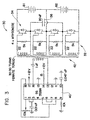
- Fig. 3 illustrates an alternate, modular, form of a system 30.
- the system 30 incorporates a bridge-type structure 32 having a plurality of solid state switches 34 for the purpose of equalizing voltages on batteries B1 and B2.
- the system of 30 requires only a single capacitor 36.
- a control element 40 generates a clock signal. This signal via transformer 42 gates the switching transistor 34 such that charge is transferred back and forth between the batteries B1 and B2 thereby equalizing the voltages thereof.
- the control element 40 could be implemented as an SG3526A pulse width modulation power convertor control element.
- the system 30 could be replicated for each pair of batteries. All such modules will operate independently of one another.
- Figure 4 is a graph illustrating the clock signals generated by the control circuit 40, in Fig. 3.
- the graph of Fig. 4 illustrates the waveform across the primary of the transformer 42.
- the clock signals have a time interval A wherein the capacitor 36 is coupled across one of the two batteries, B1 or B2.
- the time interval A is then followed by a time interval B wherein all of the solid state switches 34 are turned off to avoid short circuits and the like.
- the "dead time", interval B insures that all currents from interval A have ceased flowing.
- the time interval B is subsequently followed by a time interval C wherein the capacitor 36 is coupled across the other of the two batteries B2 or B1.
- the time interval C is then followed by another off time interval B and the process continues.
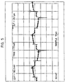
- Figure 5 illustrates the changing voltage across the capacitor 36 as the different voltages of battery B1 and B2 are being equalized, in accordance with the above-described clock signal from Figure 4.
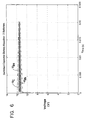
- Figure 6 is a graph of an accelerated simulation of change transfer and equalization between two batteries, such as the batteries B1 and B2 in a circuit of the type illustrated in Figure 3. While Fig. 6 is a simulation, it illustrates a process of battery equalization in accordance with the present invention.
- the simulation of Figure 6 is based on equalizing charge between two batteries which start with a one volt variation therebetween, for example, battery B1 initially starts at 12 volts and battery B2 initially starts at 11 volts.
- the graph of Figure 6 is based on the assumption that the batteries B1 and B2 are of relatively low capacity. The only difference if a simulation were run with high capacity batteries, would be that the time interval necessary to equalize the batteries would increase. Otherwise the process would be the same.
- Sandwiched between the approaching voltages of the batteries B1 and B2 is a simulated graph of the varying voltage across a capacitor such as the capacitor 36 of Figure 3.
- a capacitor value of 1000 microfareds was selected.
- the switching frequency was set at 5000 hertz.
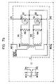
- Figure 7a is a more detailed block diagram of the system 10 illustrated in Figure 1, but limited to four batteries.
- the limitation of four batteries is exemplary only and is not a limitation of the present invention.
- the master clock unit 12a illustrated in Figure 7a represents the function of the control unit 12 of Figure 1.
- the systems of Figures 1 and 7a incorporate a single synchronized control unit 12 which provides a common master clock on lines MC1, MC2. Those signals correspond generally to the gate signals G and G illustrated in Figures 1 and 2.
- Figure 7b is a schematic diagram of one of the single pole, double throw switches illustrated in Figure 7a. While neither Figure 1 nor Figure 7a are explicitly configured to illustrate a modular arrangement of capacitors and associated switches, it will be understood that, as previously discussed with respect to Fig. 3, either one of those systems could be configured modularly. In a modular configuration, each of the capacitor/switch modules could be arranged with a plug so as to be releasably engageable with the system for maintenance and test purposes.
- FIG 8 illustrates an alternate form of an equalizing system 60 which incorporates an asynchronous control strategy.
- the system 60 includes control units 62a, 62b and 62c. Each of the control units 62a-62c generates an independent clock 64a-64c. While the system 60 illustrates equalization of four series connected batteries, it will be understood that the number of batteries being equalized is not a limitation thereof.
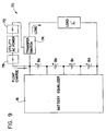
- Figure 9 illustrates an equalizer system, such as the system 16, for example, used in a system 70 where batteries provide backup in the event of a failure of utility supplied AC power.
- Typical examples include backup systems found in telecommunications and data processing systems so as to maintain operational, data and service integrity of such systems when there has been a failure of utility supplied AC power.
- the system 70 incorporates only four series connected batteries. It will be understood that such are exemplary only and the system is not limited by the number of series connected batteries.
- rectifier and circuitry 78 is provided, powered by the normal utility supplied AC energy, to provide a trickle-type float charge to a battery bank, Ba--Bn.
- the battery equalizer functions as described above to continuously equalize the voltage appearing across the series connected plurality of batteries.
- the transfer switch 74 switches to the backup battery bank for purposes of driving the load L'. During this time, the battery equalizer system 16 continues to function to equalize the voltage present on the series connected batteries.
- each of the batteries illustrated in the system 70 could itself be a composite of a plurality of batteries which were connected together in parallel to provide increased energy storage capacity. It will also be understood that the system 16 could be configured to equalize voltages on two separate batteries, wherein one of the two batteries is a primary battery, and the other is a backup battery.
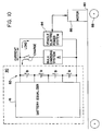
- FIG 10 is a block diagram of an electrically powered vehicle 80 which incorporates a battery equalization system 16 of the type illustrated in Fig. 7a.
- the vehicle 80 further includes a plurality of series connected rechargeable drive batteries 82, a recharging system R, and electric power system circuitry 84.
- the circuitry 84 is in turn coupled to one or more drive motors 86 which are energized to turn one or more of the wheels 88 of the vehicle to move same.
- the equalizer 16 could be installed within or carried on a battery pack housing indicated generally at 90.
- the housing 90 could be itself configured as a removable module for maintenance and test purposes.
- FIG 11 illustrates a system 16a embodying the present invention, which system is a variation of the system 16.
- the system 16a incorporates a plurality of inductors 92.
- Each member of the plurality of inductors 92 is coupled to a respective capacitor.
- the inductors 92 in combination with the associated capacitors provide circuits which exhibit resonant-like characteristics. As such, the peak currents which flow to and from the respective capacitors will be larger than in equalizer systems without inductors. Because of the resonant characteristic the current flows will now exhibit zero crossings. Switching can in turn be carried out at the current zeros to avoid losses encountered in the switching process.
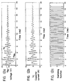
- Figures 12a through 12c are graphs illustrating a process of equalizing two series coupled batteries using an equalizing system as in Fig. 11, such as the system 16a, wherein each storage capacitor has an inductor coupled thereto.
- the inductor has a value of 100 ⁇ H
- the capacitor has a value of 100 ⁇ F.
- the frequency of the master clock signal is 1.67kHz.
- the voltages across the 2 batteries, VBa and VBb are illustrated as varying and tracking toward one another in response to the capacitor C1 being alternately switched across one battery to the next.
- the voltage across the capacitor, VC1 is also illustrated in Fig. 12a.
- Fig. 12b illustrates the current through capacitor C1 and inductor L1 in response to the switching and equalizing process. As described previously, the inductor L1 produces current peaks and current zeros during the process.
- Fig. 12c illustrates the waveform of the master clock, see Fig. 11. Switching takes place only at zero crossings of the capacitor current, illustrated in Fig. 12b.
- the switching waveform 12c can be provided with a third "dead time" state as previously illustrated in connection with the switching waveform of Fig. 4.
- the inductors prevent high current flows in the event of a momentary short circuit, so the dead time is not essential.
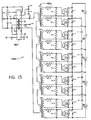
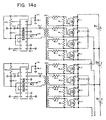
- Figure 13 is a schematic diagram of an equalizer system, 16b, such as the system 16 of Fig. 7a.
- the system 16b is illustrated equalizing five batteries Ba--Be.
- the system 16b incorporates a control element 40 of the type illustrated in connection with the system of Fig. 3.
- the system 16b also incorporates a multiple coil transformer 42a similar to the transformer 42 of Fig. 3.
- the equalizing capacitors and solid state switches of Fig. 7b have been incorporated into the system 16b.
- a string of N batteries can be equalized using a single controller with a synchronized clock signal.
- a total of N single-pole, double-throw switches and N-1 capacitors is required in this implementation.
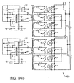
- Figure 14 illustrates a schematic of a system 60a corresponding to the system 60 of Fig. 8.
- the system 60a for exemplary purposes only, is illustrated equalizing a string of five series connected batteries using an asynchronous control arrangement.
- N batteries require N-1 independent controllers and 2N-2 single-pole double-throw switches as illustrated in Fig. 14.
Landscapes
- Engineering & Computer Science (AREA)
- Power Engineering (AREA)
- Charge And Discharge Circuits For Batteries Or The Like (AREA)
- Electric Propulsion And Braking For Vehicles (AREA)
- Circuits Of Receivers In General (AREA)
- Filters That Use Time-Delay Elements (AREA)
- Viewfinders (AREA)
Claims (14)
- Vorrichtung zum Ausgleichen der Ausgangsspannungen von mindestens zwei Batterien, umfassend:ein kapazitives Speicherelement;mit dem Speicherelement verbundene erste und zweite Umschalt-Schaltungen; undeine Steuerschaltung, wobei die Steuerschaltung mit den Umschalt-Schaltungen verbunden ist, damit sie die Umschalt-Schaltungen kontrolliert, und die Umschalt-Schaltungen abhängig von der Steuerschaltung das Speicherelement mit einer ersten Batterie und anschließend mit der anderen Batterie verbinden, so dass die Ausgangsspannungen der Batterien angeglichen werden;dadurch gekennzeichnet, dass eine Induktivität mit dem Speicherelement verbunden ist, so dass die erste und die zweite Umschalt-Schaltung resonanzartige Eigenschaften zeigen, und die Steuerschaltung dafür ausgelegt ist, das kapazitive Speicherelement bei verschwindendem Durchgangsstrom mit jeder Batterie zu verbinden.
- Vorrichtung nach Anspruch 1, wobei sowohl die erste als auch die zweite Umschalt-Schaltung umfassen:mindestens einen ersten und einen zweiten Festkörperschalter, wobei die Schalter jeweils eine Polklemme und mindestens einen Ausgangsanschluss aufweisen, und worin die Ausgangsanschlüsse mit den jeweiligen Batterien verbunden sind; unddass die Polanschlüsse eines jeden Schalters mit dem Speicherelement verbunden sind, wodurch elektrische Energie von einer Batterie auf das Speicherelement übertragen werden kann und anschließend auf die andere Batterie, so dass die Batteriespannungen angeglichen werden.
- Vorrichtung nach Anspruch 2, die ein Steuerelement enthält, das mit den Polklemmen verbunden ist.
- Vorrichtung nach irgendeinem der vorhergehenden Ansprüche, wobei jeder Schalter einen zweiten Ausgangsanschluss besitzt und jeder Schalter eine einpolige Umschaltfunktion aufweist.
- Vorrichtung nach irgendeinem der vorhergehenden Ansprüche, wobei die Vorrichtung eine Anzahl in Reihe geschalteter Batterien und eine Anzahl Ausgleichskondensatoren enthält, die mit einer Anzahl Schalter verbunden sind.
- Vorrichtung nach Anspruch 5, wobei die Vorrichtung eine gemeinsame Taktquelle enthält, die mit den Schaltern verbunden ist, und die Schalter jeden Kondensator mit einer Batterie und anschließend mit einer anderen Batterie verbinden.
- Vorrichtung nach Anspruch 6, wobei die Vorrichtung eine Anzahl Taktquellen enthält, und Mitglieder der Anzahl mit ausgewählten Schaltern verbunden sind.
- Elektrisches Fahrzeug, umfassend:ein bewegliches Fahrzeug;eine Anzahl in Reihe geschalteter wieder aufladbarer Speicherzellen; undeine Anzahl Vorrichtungen gemäß irgendeinem der vorhergehenden Ansprüche zum Ausgleichen der Ausgangsspannungen der wieder aufladbaren Speicherzellen.
- Fahrzeug nach Anspruch 8, das Schaltkreise zum erneuten Aufladen der Zellen enthält.
- Fahrzeug nach Anspruch 8 oder 9, das eine Schaltung enthält, die einen elektrischen Antriebsmotor mit Energie versorgt.
- Fahrzeug nach Anspruch 10, das einen elektrischen Antriebsmotor enthält, der mit der Energieversorgungsschaltung verbunden ist und das Fahrzeug antreibt.
- System, das elektrische Gleichspannungsenergie primär von einer Wechselspannungsquelle und sekundär von einer Anzahl Batterien einer Last zuführt, wobei das System umfasst:eine Vorrichtung nach irgendeinem der Ansprüche 1 bis 7:einen Übertragungsschalter; undein Wechselspannungs-Gleichspannungs-Umwandlungssystem.
- System nach Anspruch 12, das einen Ausgang hat, der an eine Last angeschlossen werden kann, die ein Teil eines Telekommunikationssystems ist, wobei der Übertragungsschalter automatisch vom einem ersten Energiezufuhrstatus zur Last aus der Wechselspannungsquelle auf einen zweiten Energiezufuhrstatus von mindestens einer der Batterien umschaltet, und zwar abhängig von einem Ausfall der Wechselspannungsenergie
- System nach Anspruch 12 oder 13, das einen Ausgang hat, der an eine Last angeschlossen werden kann, die ein Teil eines Datenverarbeitungssystems ist, wobei der Übertragungsschalter automatisch vom einem ersten Energiezufuhrstatus zur Last aus der Wechselspannungsquelle auf einen zweiten Energiezufuhrstatus von mindestens einer der Batterien umschaltet, und zwar abhängig von einem Ausfall der Wechselspannungsenergie.
Applications Claiming Priority (3)
| Application Number | Priority Date | Filing Date | Title |
|---|---|---|---|
| US08/650,490 US5710504A (en) | 1996-05-20 | 1996-05-20 | Switched capacitor system for automatic battery equalization |
| US650490 | 1996-05-20 | ||
| PCT/US1997/008554 WO1997044877A1 (en) | 1996-05-20 | 1997-05-20 | Switched capacitor system for automatic battery equalization |
Publications (3)
| Publication Number | Publication Date |
|---|---|
| EP0900465A1 EP0900465A1 (de) | 1999-03-10 |
| EP0900465A4 EP0900465A4 (de) | 2003-04-23 |
| EP0900465B1 true EP0900465B1 (de) | 2007-08-08 |
Family
ID=24609140
Family Applications (1)
| Application Number | Title | Priority Date | Filing Date |
|---|---|---|---|
| EP97926627A Expired - Lifetime EP0900465B1 (de) | 1996-05-20 | 1997-05-20 | System mit geschalteten kondensatoren zum automatischen batterieausgleich |
Country Status (8)
| Country | Link |
|---|---|
| US (1) | US5710504A (de) |
| EP (1) | EP0900465B1 (de) |
| JP (1) | JP2000511398A (de) |
| AT (1) | ATE369650T1 (de) |
| AU (1) | AU3134697A (de) |
| CA (1) | CA2255970C (de) |
| DE (1) | DE69737994D1 (de) |
| WO (1) | WO1997044877A1 (de) |
Families Citing this family (163)
| Publication number | Priority date | Publication date | Assignee | Title |
|---|---|---|---|---|
| JP3099181B2 (ja) * | 1996-09-10 | 2000-10-16 | 本田技研工業株式会社 | 蓄電器の電圧制御装置 |
| US5900716A (en) * | 1997-03-03 | 1999-05-04 | Northrop Grumman Corporation | Balanced battery charger |
| US6031355A (en) * | 1997-08-16 | 2000-02-29 | Rich; Joe G. | Circuit utilizing current flowing from a high-potential battery bank to a low-potential battery bank |
| JP3746886B2 (ja) | 1997-09-29 | 2006-02-15 | 三菱自動車工業株式会社 | 蓄電装置 |
| JP3368527B2 (ja) | 1997-09-29 | 2003-01-20 | 三菱自動車工業株式会社 | スイッチング装置 |
| FR2776139B1 (fr) * | 1998-03-13 | 2002-03-08 | Denso Corp | Dispositif d'equilibrage des tensions dans une batterie composee |
| JP3899700B2 (ja) * | 1998-09-03 | 2007-03-28 | 株式会社デンソー | 組電池の電圧調整装置及び組電池の電圧調整方法 |
| US6259229B1 (en) * | 1998-04-30 | 2001-07-10 | Daimlerchrysler Corporation | Circulating current battery heater |
| US6064178A (en) * | 1998-05-07 | 2000-05-16 | Ford Motor Company | Battery charge balancing system having parallel switched energy storage elements |
| US5986909A (en) * | 1998-05-21 | 1999-11-16 | Robicon Corporation | Multiphase power supply with plural series connected cells and failed cell bypass |
| CA2291831A1 (en) | 1998-12-11 | 2000-06-11 | Chaz G. Haba | Battery network with compounded interconnections |
| KR20010006576A (ko) * | 1999-01-18 | 2001-01-26 | 가나이 쓰도무 | 전력축적수단의 충방전장치 및 그것을 사용한전력축적수단의 제조방법 |
| US6121751A (en) * | 1999-03-11 | 2000-09-19 | Lockheed Martin Corporation | Battery charger for charging a stack of multiple lithium ion battery cells |
| JP4022797B2 (ja) * | 1999-03-29 | 2007-12-19 | 株式会社ジーエス・ユアサコーポレーション | 群電池の容量平準化回路 |
| US6260649B1 (en) * | 1999-03-29 | 2001-07-17 | Robert S. Carney, Jr. | Energy conserving electric vehicle |
| US6140800A (en) * | 1999-05-27 | 2000-10-31 | Peterson; William Anders | Autonomous battery equalization circuit |
| US6140799A (en) * | 1999-06-29 | 2000-10-31 | Thomasson; Mark J. | Switched battery-bank assembly for providing incremental voltage control |
| JP3466513B2 (ja) * | 1999-08-02 | 2003-11-10 | 日産ディーゼル工業株式会社 | 電気自動車の電源システム |
| JP3280642B2 (ja) * | 1999-09-08 | 2002-05-13 | 長野日本無線株式会社 | 蓄電モジュール |
| US6222344B1 (en) | 1999-12-06 | 2001-04-24 | Bae Systems Controls, Inc. | Magnetically coupled autonomous battery equalization circuit |
| US6518725B2 (en) * | 2000-01-28 | 2003-02-11 | Semtech Corporation | Charge balancing system |
| US6642692B2 (en) * | 2000-06-23 | 2003-11-04 | Honda Giken Kogyo Kabushiki Kaisha | Charge equalizing device for power storage unit |
| WO2002071734A2 (en) * | 2000-12-19 | 2002-09-12 | Smal Camera Technologies, Inc. | Compact digital camera system |
| US6452363B1 (en) | 2000-12-28 | 2002-09-17 | C. E. Niehoff & Co. | Multiple battery charge equalizer |
| AUPR269301A0 (en) * | 2001-01-24 | 2001-02-22 | Cochlear Limited | Power supply for a cochlear implant |
| US8026637B2 (en) | 2001-01-24 | 2011-09-27 | Cochlear Limited | Power supply having an auxiliary power cell |
| US6559621B2 (en) * | 2001-05-21 | 2003-05-06 | Cellex Power Products, Inc. | Hybrid energy storage device charge equalization system and method |
| US7615966B2 (en) * | 2001-05-25 | 2009-11-10 | Texas Instruments Northern Virginia Incorporated | Method and apparatus for managing energy in plural energy storage units |
| DE10139048A1 (de) * | 2001-08-08 | 2003-02-20 | Bosch Gmbh Robert | Verfahren und Vorrichtung zur Durchführung eines automatischen Ladezustandsausgleichs |
| CA2406500C (en) | 2001-10-01 | 2008-04-01 | Research In Motion Limited | An over-voltage protection circuit for use in a charging circuit |
| JP3809549B2 (ja) * | 2001-11-22 | 2006-08-16 | 株式会社日立製作所 | 電源装置と分散型電源システムおよびこれを搭載した電気自動車 |
| AU2003251306A1 (en) * | 2002-05-20 | 2003-12-12 | Good Ideas Llc | Ultracapacitor balancing circuit |
| US6841971B1 (en) | 2002-05-29 | 2005-01-11 | Alpha Technologies, Inc. | Charge balancing systems and methods |
| US7714538B2 (en) | 2002-11-22 | 2010-05-11 | Milwaukee Electric Tool Corporation | Battery pack |
| US7253585B2 (en) | 2002-11-22 | 2007-08-07 | Milwaukee Electric Tool Corporation | Battery pack |
| US7245108B2 (en) * | 2002-11-25 | 2007-07-17 | Tiax Llc | System and method for balancing state of charge among series-connected electrical energy storage units |
| US6806686B1 (en) | 2003-04-25 | 2004-10-19 | Maxwell Technologies, Inc. | Charge balancing circuit |
| WO2004097868A2 (en) * | 2003-04-25 | 2004-11-11 | Maxwell Technologies, Inc. | Charge balancing circuit for double-layer capacitors |
| US6836098B1 (en) | 2003-06-10 | 2004-12-28 | O'brien Robert Neville | Battery charging method using supercapacitors at two stages |
| WO2005015584A2 (en) * | 2003-08-06 | 2005-02-17 | Biosource, Inc | Power efficient flow through capacitor system |
| US20050077879A1 (en) * | 2003-10-14 | 2005-04-14 | Near Timothy Paul | Energy transfer device for series connected energy source and storage devices |
| JP2005160233A (ja) * | 2003-11-26 | 2005-06-16 | Makita Corp | 組電池及び電池パック |
| US20050269988A1 (en) * | 2004-06-04 | 2005-12-08 | Maxwell Technologies, Inc. | Voltage balancing circuit for multi-cell modules |
| US20060097697A1 (en) * | 2004-11-10 | 2006-05-11 | Eaglepicher Technologies, Llc | Method and system for cell equalization with switched charging sources |
| US7928691B2 (en) * | 2004-11-10 | 2011-04-19 | EaglePicher Technologies | Method and system for cell equalization with isolated charging sources |
| US20060097700A1 (en) * | 2004-11-10 | 2006-05-11 | Eaglepicher Technologies, Llc | Method and system for cell equalization with charging sources and shunt regulators |
| JP2006166615A (ja) * | 2004-12-08 | 2006-06-22 | Fuji Heavy Ind Ltd | 蓄電デバイスの電圧均等化制御システム |
| CN101088203B (zh) * | 2004-12-24 | 2010-08-18 | Lg化学株式会社 | 用于在具有多个锂离子电池的电池组中控制电压平衡的系统及其方法 |
| JP2006246646A (ja) * | 2005-03-04 | 2006-09-14 | Yazaki Corp | 均等化方法及びその装置 |
| US7598711B2 (en) * | 2005-11-23 | 2009-10-06 | Apple Inc. | Power source switchover apparatus and method |
| USD558670S1 (en) | 2006-01-09 | 2008-01-01 | Milwaukee Electric Tool Corporation | Battery |
| US20070173090A1 (en) * | 2006-01-10 | 2007-07-26 | Johnson Todd W | Battery pack |
| US7605492B2 (en) * | 2006-04-21 | 2009-10-20 | Ford Global Technologies, Llc | Power supply system and method for supplying power to a vehicle |
| US8058844B2 (en) * | 2006-05-31 | 2011-11-15 | Aeroflex Plainview, Inc. | Low-power battery system |
| JP4356708B2 (ja) * | 2006-06-23 | 2009-11-04 | トヨタ自動車株式会社 | 電源システムおよびそれを備える車両 |
| JP4560501B2 (ja) * | 2006-08-11 | 2010-10-13 | 矢崎総業株式会社 | 充電状態調整装置 |
| US20080129031A1 (en) * | 2006-11-03 | 2008-06-05 | Nelsen Larry A | Spray Protection Device |
| US7994657B2 (en) * | 2006-12-22 | 2011-08-09 | Solarbridge Technologies, Inc. | Modular system for unattended energy generation and storage |
| TWM319578U (en) * | 2007-02-09 | 2007-09-21 | Ctech Technology Corp | Voltage stabilizing circuit of power device for car |
| US7688048B2 (en) | 2007-02-21 | 2010-03-30 | American Power Conversion Corporation | 3-phase high power UPS |
| US7984776B2 (en) * | 2007-03-30 | 2011-07-26 | The Regents Of The University Of Michigan | Energy storage and control system for a vehicle electrified drivetrain |
| DE102007041526A1 (de) * | 2007-08-10 | 2009-02-12 | Robert Bosch Gmbh | Energiespeicher, insbesondere Akkumulator |
| KR101220339B1 (ko) * | 2007-10-16 | 2013-01-09 | 한국과학기술원 | 직렬연결 배터리 스트링을 위한 자동 전하 균일 방법 및장치 |
| US7888910B2 (en) * | 2007-11-29 | 2011-02-15 | Hdm Systems Corporation | Sequencing switched single capacitor for automatic equalization of batteries connected in series |
| US8143851B2 (en) | 2008-02-15 | 2012-03-27 | Apple Inc. | Power source having a parallel cell topology |
| US20090289603A1 (en) * | 2008-05-21 | 2009-11-26 | Apple Inc. | Method and apparatus for maintaining a battery in a partially charged state |
| US8063625B2 (en) | 2008-06-18 | 2011-11-22 | Apple Inc. | Momentarily enabled electronic device |
| US10283974B2 (en) | 2009-03-02 | 2019-05-07 | Volterra Semiconductor LLC | Systems and methods for intelligent, adaptive management of energy storage packs |
| US9397502B2 (en) | 2009-03-02 | 2016-07-19 | Volterra Semiconductor LLC | System and method for proportioned power distribution in power converter arrays |
| WO2010101960A1 (en) * | 2009-03-02 | 2010-09-10 | Element Energy | Systems and methods for scalable configurations of intelligent energy storage packs |
| US8519670B2 (en) | 2009-03-23 | 2013-08-27 | Motiv Power Systems, Inc. | System and method for balancing charge within a battery pack |
| US8831904B2 (en) * | 2009-08-05 | 2014-09-09 | Texas Instruments Incorporated | Cell based temperature monitoring |
| US8385091B2 (en) | 2009-08-20 | 2013-02-26 | Electric IT Corporation | 3-phase high-power UPS |
| US8800697B2 (en) | 2009-09-01 | 2014-08-12 | Ryno Motors, Inc. | Electric-powered self-balancing unicycle with steering linkage between handlebars and wheel forks |
| JP4590520B1 (ja) | 2009-09-02 | 2010-12-01 | 日本蓄電器工業株式会社 | 交流出力可能な蓄電装置 |
| JP5440918B2 (ja) * | 2009-09-02 | 2014-03-12 | 独立行政法人 宇宙航空研究開発機構 | バランス回路を備えた蓄電装置 |
| US8410783B2 (en) * | 2009-09-30 | 2013-04-02 | Apple Inc. | Detecting an end of life for a battery using a difference between an unloaded battery voltage and a loaded battery voltage |
| US8450979B2 (en) * | 2009-09-30 | 2013-05-28 | Apple Inc. | Power adapter with internal battery |
| EP2312724A1 (de) | 2009-10-19 | 2011-04-20 | 4ESys NV | System und Verfahren zum Augleichen von Energiespeichervorrichtungen |
| WO2011050109A1 (en) * | 2009-10-20 | 2011-04-28 | Motiv Power Systems, Inc. | System and method for managing a power system with multiple power components |
| US9490639B2 (en) | 2010-02-05 | 2016-11-08 | Commissariat A L'energie Atomique Et Aux Energies Alternatives | Charge equalization system for batteries |
| FR2956260B1 (fr) | 2010-02-05 | 2012-04-13 | Commissariat Energie Atomique | Systeme d'equilibrage de charge pour batteries |
| EP2363935B1 (de) * | 2010-03-04 | 2013-05-15 | Nxp B.V. | Ausgleichsschaltung für Ladungsspeicherelemente |
| US8519564B2 (en) | 2010-05-12 | 2013-08-27 | Apple Inc. | Multi-output power supply |
| HUP1000311A2 (en) | 2010-06-14 | 2012-08-28 | Ferenc Stangl | System and method for charge equalisation and/or charring of electrical energy storing units |
| DE102010039913A1 (de) * | 2010-08-30 | 2012-03-01 | Sb Limotive Company Ltd. | Verfahren zum Ausbalancieren von Ladezuständen einer Batterie mit mehreren Batteriezellen sowie ein entsprechendes Batteriemanagementsystem und eine Batterie |
| US9496724B2 (en) | 2010-09-23 | 2016-11-15 | Stmicroelectronics Application Gmbh | Active battery balancing circuit and method of balancing an electric charge in a plurality of cells of a battery |
| WO2012040496A1 (en) * | 2010-09-23 | 2012-03-29 | Stmicroelectronics Application Gmbh | Active battery balancing circuit and method of balancing an electric charge in a plurality of cells of a battery |
| WO2012056417A2 (en) | 2010-10-29 | 2012-05-03 | Sendyne Corp. | Charge redistribution method for cell arrays |
| US8723482B2 (en) * | 2010-11-04 | 2014-05-13 | Elite Power Solutions Llc | Battery unit balancing system |
| EP2656467B1 (de) | 2010-12-22 | 2016-10-12 | GE Energy Power Conversion Technology Limited | Kondensatorsymmetrierungsschaltung und steuerverfahren für eine elektronische vorrichtung wie einen mehrstufigen wechselrichter |
| CN103493351B (zh) | 2010-12-22 | 2017-10-24 | 通用电气能源能量变换技术有限公司 | 多电平功率转换器电路的机械装置 |
| US8633669B2 (en) * | 2010-12-24 | 2014-01-21 | Marc Henness | Electrical circuit for controlling electrical power to drive an inductive load |
| EP2666228B1 (de) * | 2011-01-22 | 2022-08-31 | Alpha Technologies Services, Inc. | Ladungsausgleichssystem und -verfahren |
| US9018892B2 (en) * | 2011-03-23 | 2015-04-28 | Indian Institute Of Technology Bombay | Photo-voltaic array fed switched capacitor DC-DC converter based battery charging for Li-Ion batteries |
| US20140042974A1 (en) * | 2011-04-22 | 2014-02-13 | Sk Innovation Co., Ltd. | Detachable battery module, and method and apparatus for the charge equalization of a battery string using same |
| JP5814009B2 (ja) * | 2011-06-23 | 2015-11-17 | 東芝シュネデール・インバータ株式会社 | インバータ装置の電圧バランス回路 |
| JP2013046433A (ja) * | 2011-08-22 | 2013-03-04 | Seiko Instruments Inc | セルバランス装置およびバッテリシステム |
| EP2584685A1 (de) * | 2011-10-20 | 2013-04-24 | Siemens Aktiengesellschaft | Symmetrierungsschaltung für in Reihe geschalteten Zwischenkreiskondensatoren, und Verfahren zu deren Betrieb |
| WO2013061461A1 (ja) | 2011-10-28 | 2013-05-02 | ルネサスエレクトロニクス株式会社 | バッテリシステム |
| JP5939702B2 (ja) * | 2011-11-30 | 2016-06-22 | 矢崎総業株式会社 | 均等化装置 |
| US9041249B2 (en) | 2012-06-01 | 2015-05-26 | Blackberry Limited | Asymmetric series power packs with efficient dc-dc conversion |
| US20130328387A1 (en) * | 2012-06-08 | 2013-12-12 | Sagar Venkateswaran | Supercapacitor vehicle and roadway system |
| CN104737087B (zh) * | 2012-08-02 | 2016-08-24 | 侯经权 | 数字电压控制器 |
| US10014823B2 (en) * | 2012-08-05 | 2018-07-03 | Ben-Gurion University Of The Negev Research & Development Authority | High efficiency resonant switched capacitor converter with continuous conversion ratio |
| AU2013305694A1 (en) | 2012-08-22 | 2015-04-09 | Ryno Motors, Inc. | Electric-powered self-balancing unicycle |
| US20140103877A1 (en) * | 2012-10-16 | 2014-04-17 | Saroj Kumar Sahu | Battery management system |
| US20150244189A1 (en) * | 2012-10-24 | 2015-08-27 | Sharp Kabushiki Kaisha | Balancer circuit and battery unit using same |
| US10003293B2 (en) | 2013-03-15 | 2018-06-19 | Andrew John Bartlik | Portable motor drive system |
| US9160330B2 (en) * | 2013-05-02 | 2015-10-13 | Texas Instruments Incorporated | Boost capacitor sharing architecture for power supply active balancing systems |
| JP6135375B2 (ja) * | 2013-08-02 | 2017-05-31 | 住友電気工業株式会社 | 蓄電装置、充電方法及び放電方法 |
| JP6065782B2 (ja) * | 2013-08-12 | 2017-01-25 | 住友電気工業株式会社 | 蓄電装置、充電方法及び放電方法 |
| US9673658B2 (en) * | 2014-03-06 | 2017-06-06 | Samsung Electro-Mechanics Co., Ltd. | Non-contact capacitive coupling type power charging apparatus and non-contact capacitive coupling type battery apparatus |
| DE102014207826A1 (de) * | 2014-04-25 | 2015-10-29 | Robert Bosch Gmbh | Vorrichtung und Verfahren zum Ladungsausgleich von elektrischen Energiespeicherzellen |
| TW201543785A (zh) * | 2014-05-14 | 2015-11-16 | Fu-Zi Xu | 阻尼充電裝置 |
| US10833523B2 (en) * | 2014-06-10 | 2020-11-10 | Kagra Inc. | Electricity storage element charging method and electricity storage device |
| JP6356518B2 (ja) * | 2014-07-25 | 2018-07-11 | ゼネラル・エレクトリック・カンパニイ | バッテリ管理システムおよび方法 |
| CN105576719B (zh) * | 2014-10-08 | 2018-12-11 | 香港理工大学 | 一种电压均衡电路 |
| DE102015002152B3 (de) * | 2015-02-18 | 2016-05-12 | Audi Ag | Batterie für ein Kraftfahrzeug, Kraftfahrzeug und Verfahren zum Betreiben einer Batterie |
| US10703211B2 (en) | 2015-03-16 | 2020-07-07 | Thunder Power New Energy Vehicle Development Company Limited | Battery pack, battery charging station, and charging method |
| US9954260B2 (en) | 2015-03-16 | 2018-04-24 | Thunder Power New Energy Vehicle Development Company Limited | Battery system with heat exchange device |
| US9550406B2 (en) | 2015-03-16 | 2017-01-24 | Thunder Power Hong Kong Ltd. | Thermal dissipation system of an electric vehicle |
| US10173687B2 (en) | 2015-03-16 | 2019-01-08 | Wellen Sham | Method for recognizing vehicle driver and determining whether driver can start vehicle |
| US9499067B2 (en) | 2015-03-16 | 2016-11-22 | Thunder Power Hong Kong Ltd. | Power management in electric vehicles |
| DE102015106773A1 (de) | 2015-04-30 | 2016-11-03 | Dr. Ing. H.C. F. Porsche Aktiengesellschaft | Batteriesystem mit Batteriesteuerung |
| CN105216646B (zh) * | 2015-10-28 | 2017-10-20 | 北京新能源汽车股份有限公司 | 电动汽车的电池包均衡系统和均衡方法 |
| DE102017206254B4 (de) | 2016-04-13 | 2024-07-11 | Dialog Semiconductor (Uk) Limited | DC-DC-Umwandlung für Mehrzellen-Batterien |
| DK179053B1 (en) * | 2016-04-16 | 2017-09-18 | Lithium Balance As | Cell balancing method and system |
| US20180076644A1 (en) * | 2016-09-14 | 2018-03-15 | Kilowatt Labs, Inc. | Supercapacitor based energy storage device |
| US11251628B2 (en) | 2017-01-23 | 2022-02-15 | Rafael Advanced Defense Systems Ltd. | System for balancing a series of cells |
| US10283173B2 (en) | 2017-04-19 | 2019-05-07 | Seagate Technologies Llc | Intelligent backup capacitor management |
| US10625626B2 (en) * | 2017-11-29 | 2020-04-21 | Nio Usa, Inc. | Charging systems and methods for electric vehicles |
| WO2019147244A1 (en) * | 2018-01-25 | 2019-08-01 | Volvo Construction Equipment Ab | Equalizer overload management |
| US10363828B1 (en) | 2018-06-12 | 2019-07-30 | Nio Usa, Inc. | Systems and methods for regulating charging of electric vehicles |
| US11621441B2 (en) * | 2018-07-27 | 2023-04-04 | The Boeing Company | Li-Ion battery high voltage distribution system architecture |
| JP7095587B2 (ja) * | 2018-12-17 | 2022-07-05 | トヨタ自動車株式会社 | 電池システム、電動車両およびその制御方法 |
| CN111917147A (zh) * | 2019-05-10 | 2020-11-10 | 立锜科技股份有限公司 | 充电电路与充电控制方法 |
| JP7059982B2 (ja) * | 2019-05-27 | 2022-04-26 | 株式会社オートネットワーク技術研究所 | 車載用バックアップ電源装置 |
| CN110048494B (zh) * | 2019-05-30 | 2023-05-12 | 广东工业大学 | 一种电池单体电压主动均衡系统 |
| US11685276B2 (en) | 2019-06-07 | 2023-06-27 | Anthony Macaluso | Methods and apparatus for powering a vehicle |
| US11615923B2 (en) | 2019-06-07 | 2023-03-28 | Anthony Macaluso | Methods, systems and apparatus for powering a vehicle |
| US11289974B2 (en) | 2019-06-07 | 2022-03-29 | Anthony Macaluso | Power generation from vehicle wheel rotation |
| US11222750B1 (en) | 2021-03-22 | 2022-01-11 | Anthony Macaluso | Hypercapacitor apparatus for storing and providing energy |
| US11837411B2 (en) | 2021-03-22 | 2023-12-05 | Anthony Macaluso | Hypercapacitor switch for controlling energy flow between energy storage devices |
| US11641572B2 (en) | 2019-06-07 | 2023-05-02 | Anthony Macaluso | Systems and methods for managing a vehicle's energy via a wireless network |
| US10924008B2 (en) | 2019-07-09 | 2021-02-16 | Nio Usa, Inc. | Devices, systems, and methods for charging electric vehicles |
| WO2021010388A1 (ja) | 2019-07-18 | 2021-01-21 | ヌヴォトンテクノロジージャパン株式会社 | 電池管理回路および蓄電装置 |
| WO2021015066A1 (ja) | 2019-07-25 | 2021-01-28 | ヌヴォトンテクノロジージャパン株式会社 | 電池管理回路、蓄電装置および電池管理方法 |
| US11545841B2 (en) * | 2019-11-18 | 2023-01-03 | Semiconductor Components Industries, Llc | Methods and apparatus for autonomous balancing and communication in a battery system |
| CN112838624B (zh) * | 2019-11-22 | 2024-02-06 | 圣邦微电子(北京)股份有限公司 | 一种电源电路 |
| US20210408807A1 (en) * | 2020-06-30 | 2021-12-30 | Avx Corporation | System and Method for Balancing Ultracapacitors |
| IL276933A (en) * | 2020-08-25 | 2022-03-01 | Irp Nexus Group Ltd | An advanced battery array management system, for comparing loads in storage cells connected in series |
| JP2022106568A (ja) * | 2021-01-07 | 2022-07-20 | 本田技研工業株式会社 | 充電システム |
| CN113595221B (zh) * | 2021-08-11 | 2025-02-07 | 中国科学院电工研究所 | 一种复合电源模块及复合电源均衡系统 |
| GB2609999B (en) * | 2021-08-20 | 2024-01-31 | Cirrus Logic Int Semiconductor Ltd | Cell balancing |
| US11577606B1 (en) | 2022-03-09 | 2023-02-14 | Anthony Macaluso | Flexible arm generator |
| US11472306B1 (en) | 2022-03-09 | 2022-10-18 | Anthony Macaluso | Electric vehicle charging station |
| US12160132B2 (en) | 2023-01-30 | 2024-12-03 | Anthony Macaluso | Matable energy storage devices |
| US11955875B1 (en) | 2023-02-28 | 2024-04-09 | Anthony Macaluso | Vehicle energy generation system |
| US12407219B2 (en) | 2023-02-28 | 2025-09-02 | Anthony Macaluso | Vehicle energy generation system |
| US12412430B2 (en) | 2023-12-22 | 2025-09-09 | Anthony Macaluso | Systems and methods for managing a vehicle's energy via a wireless network |
| US20250239869A1 (en) * | 2024-01-19 | 2025-07-24 | Caterpillar Inc. | Active inter-cell balancing method |
| CN119543382B (zh) * | 2025-01-23 | 2025-07-15 | 深圳市乐祺微电子科技有限公司 | 一种实时调整电池压差的主动均衡电路及方法 |
Family Cites Families (15)
| Publication number | Priority date | Publication date | Assignee | Title |
|---|---|---|---|---|
| US4079303A (en) * | 1976-07-28 | 1978-03-14 | The United States Of America As Represented By The United States Department Of Energy | Charging system and method for multicell storage batteries |
| US4479083B1 (en) * | 1982-09-30 | 1998-09-01 | Vanner Weldon Inc | DC power system having battery voltage equalizer circuit |
| US4502000A (en) * | 1983-07-19 | 1985-02-26 | Energy Development Associates, Inc. | Device for balancing parallel strings |
| US4502001A (en) * | 1983-07-19 | 1985-02-26 | Energy Development Associates, Inc. | Current balancing for battery strings |
| US4949028A (en) * | 1988-10-18 | 1990-08-14 | Sure Power, Inc. | Multiple voltage battery charge balancing and load protecting device |
| US5184025A (en) * | 1988-11-14 | 1993-02-02 | Elegant Design Solutions, Inc. | Computer-controlled uninterruptible power supply |
| US5003244A (en) * | 1989-05-09 | 1991-03-26 | Digital Equipment Corporation | Battery charger for charging a plurality of batteries |
| US4967136A (en) * | 1989-09-25 | 1990-10-30 | Prestolite Electric Incorporated | Battery equalization circuit for a dual voltage charging system |
| DE3940929C1 (de) * | 1989-12-12 | 1991-05-08 | Fraunhofer-Gesellschaft Zur Foerderung Der Angewandten Forschung Ev, 8000 Muenchen, De | |
| US5479083A (en) * | 1993-06-21 | 1995-12-26 | Ast Research, Inc. | Non-dissipative battery charger equalizer |
| DE4427077C1 (de) * | 1994-07-30 | 1996-03-21 | Fraunhofer Ges Forschung | Vorrichtung zum Ladungsaustausch zwischen einer Vielzahl von in Reine geschalteten Energiespeichern oder -wandlern |
| FR2724501A1 (fr) * | 1994-09-09 | 1996-03-15 | Ray O Vac Corp | Appareil egaliseur de charge pour des batteries connectees en serie |
| US5622789A (en) * | 1994-09-12 | 1997-04-22 | Apple Computer, Inc. | Battery cell having an internal circuit for controlling its operation |
| JP2716374B2 (ja) * | 1994-09-28 | 1998-02-18 | インターナショナル・ビジネス・マシーンズ・コーポレイション | 情報処理機器、情報処理機器のための給電装置及び給電方法 |
| US5528122A (en) * | 1994-11-29 | 1996-06-18 | Ventron Corporation | Battery voltage equalizer circuit |
-
1996
- 1996-05-20 US US08/650,490 patent/US5710504A/en not_active Expired - Lifetime
-
1997
- 1997-05-20 DE DE69737994T patent/DE69737994D1/de not_active Expired - Lifetime
- 1997-05-20 CA CA002255970A patent/CA2255970C/en not_active Expired - Fee Related
- 1997-05-20 AU AU31346/97A patent/AU3134697A/en not_active Abandoned
- 1997-05-20 AT AT97926627T patent/ATE369650T1/de not_active IP Right Cessation
- 1997-05-20 WO PCT/US1997/008554 patent/WO1997044877A1/en not_active Ceased
- 1997-05-20 EP EP97926627A patent/EP0900465B1/de not_active Expired - Lifetime
- 1997-05-20 JP JP09542657A patent/JP2000511398A/ja active Pending
Also Published As
| Publication number | Publication date |
|---|---|
| JP2000511398A (ja) | 2000-08-29 |
| WO1997044877A1 (en) | 1997-11-27 |
| ATE369650T1 (de) | 2007-08-15 |
| EP0900465A4 (de) | 2003-04-23 |
| CA2255970C (en) | 2004-11-09 |
| AU3134697A (en) | 1997-12-09 |
| US5710504A (en) | 1998-01-20 |
| DE69737994D1 (de) | 2007-09-20 |
| CA2255970A1 (en) | 1997-11-27 |
| EP0900465A1 (de) | 1999-03-10 |
Similar Documents
| Publication | Publication Date | Title |
|---|---|---|
| EP0900465B1 (de) | System mit geschalteten kondensatoren zum automatischen batterieausgleich | |
| US7282814B2 (en) | Battery controller and method for controlling a battery | |
| Daowd et al. | Passive and active battery balancing comparison based on MATLAB simulation | |
| US6538414B1 (en) | Electric energy storage device with cell energy control, and method of controlling cell energy | |
| CN101467328B (zh) | 电荷均衡设备 | |
| US5631534A (en) | Bidirectional current pump for battery charge balancing | |
| US6064178A (en) | Battery charge balancing system having parallel switched energy storage elements | |
| JP3217529U (ja) | 蓄電池および蓄電池管理システム | |
| Yildirim et al. | Evaluation and comparison of battery cell balancing methods | |
| EP2548283A2 (de) | Managementsysteme für batteriezellenumrichter | |
| WO2010114806A1 (en) | Power management circuit for rechargeable battery stack | |
| KR102017607B1 (ko) | 재충전가능 배터리 시스템 및 재충전가능 배터리 시스템 작동 방법 | |
| KR20140007355A (ko) | 재충전가능 배터리 시스템 및 재충전가능 배터리 시스템 작동 방법 | |
| EP2135339A1 (de) | System und verfahren zum ausgleichen eines ladungszustands von in reihe geschalteten zellen | |
| KR20140034132A (ko) | 재충전가능 배터리 시스템 및 재충전가능 배터리 시스템 작동 방법 | |
| JP3606779B2 (ja) | 電気自動車の電源システム | |
| WO2012042401A2 (en) | Charge balancing system | |
| JPH11103535A (ja) | 蓄電装置 | |
| WO2014020582A2 (en) | Method for providing adjustable power from battery packs, discrete power distribution unit for electric vehicles | |
| Ekanayake et al. | Active and passive based hybrid cell balancing approach to series connected lithium-ion battery pack | |
| Marcin et al. | Overview of active balancing methods and simulation of capacitor based active cell balancing for battery pack in EV | |
| JP2001268815A (ja) | 充電回路 | |
| Ketzer et al. | Evaluating circuit topologies for battery charge equalization | |
| JP2001251777A (ja) | 充放電方法 | |
| UA159421U (uk) | Система балансування літій-іонних акумуляторних батарей |
Legal Events
| Date | Code | Title | Description |
|---|---|---|---|
| PUAI | Public reference made under article 153(3) epc to a published international application that has entered the european phase |
Free format text: ORIGINAL CODE: 0009012 |
|
| 17P | Request for examination filed |
Effective date: 19981218 |
|
| AK | Designated contracting states |
Kind code of ref document: A1 Designated state(s): AT BE CH DE DK ES FI FR GB GR IE IT LI LU MC NL PT SE |
|
| A4 | Supplementary search report drawn up and despatched |
Effective date: 20030307 |
|
| RIC1 | Information provided on ipc code assigned before grant |
Ipc: 7H 02J 9/06 B Ipc: 7H 02J 7/00 A |
|
| RA4 | Supplementary search report drawn up and despatched (corrected) |
Effective date: 20030319 |
|
| 17Q | First examination report despatched |
Effective date: 20031024 |
|
| GRAP | Despatch of communication of intention to grant a patent |
Free format text: ORIGINAL CODE: EPIDOSNIGR1 |
|
| GRAS | Grant fee paid |
Free format text: ORIGINAL CODE: EPIDOSNIGR3 |
|
| GRAA | (expected) grant |
Free format text: ORIGINAL CODE: 0009210 |
|
| AK | Designated contracting states |
Kind code of ref document: B1 Designated state(s): AT BE CH DE DK ES FI FR GB GR IE IT LI LU MC NL PT SE |
|
| REG | Reference to a national code |
Ref country code: GB Ref legal event code: FG4D |
|
| REG | Reference to a national code |
Ref country code: CH Ref legal event code: EP |
|
| REG | Reference to a national code |
Ref country code: IE Ref legal event code: FG4D |
|
| REF | Corresponds to: |
Ref document number: 69737994 Country of ref document: DE Date of ref document: 20070920 Kind code of ref document: P |
|
| PG25 | Lapsed in a contracting state [announced via postgrant information from national office to epo] |
Ref country code: NL Free format text: LAPSE BECAUSE OF FAILURE TO SUBMIT A TRANSLATION OF THE DESCRIPTION OR TO PAY THE FEE WITHIN THE PRESCRIBED TIME-LIMIT Effective date: 20070808 Ref country code: FI Free format text: LAPSE BECAUSE OF FAILURE TO SUBMIT A TRANSLATION OF THE DESCRIPTION OR TO PAY THE FEE WITHIN THE PRESCRIBED TIME-LIMIT Effective date: 20070808 Ref country code: ES Free format text: LAPSE BECAUSE OF FAILURE TO SUBMIT A TRANSLATION OF THE DESCRIPTION OR TO PAY THE FEE WITHIN THE PRESCRIBED TIME-LIMIT Effective date: 20071119 |
|
| NLV1 | Nl: lapsed or annulled due to failure to fulfill the requirements of art. 29p and 29m of the patents act | ||
| REG | Reference to a national code |
Ref country code: CH Ref legal event code: PL |
|
| PG25 | Lapsed in a contracting state [announced via postgrant information from national office to epo] |
Ref country code: AT Free format text: LAPSE BECAUSE OF FAILURE TO SUBMIT A TRANSLATION OF THE DESCRIPTION OR TO PAY THE FEE WITHIN THE PRESCRIBED TIME-LIMIT Effective date: 20070808 Ref country code: LI Free format text: LAPSE BECAUSE OF FAILURE TO SUBMIT A TRANSLATION OF THE DESCRIPTION OR TO PAY THE FEE WITHIN THE PRESCRIBED TIME-LIMIT Effective date: 20070808 Ref country code: CH Free format text: LAPSE BECAUSE OF FAILURE TO SUBMIT A TRANSLATION OF THE DESCRIPTION OR TO PAY THE FEE WITHIN THE PRESCRIBED TIME-LIMIT Effective date: 20070808 |
|
| PG25 | Lapsed in a contracting state [announced via postgrant information from national office to epo] |
Ref country code: BE Free format text: LAPSE BECAUSE OF FAILURE TO SUBMIT A TRANSLATION OF THE DESCRIPTION OR TO PAY THE FEE WITHIN THE PRESCRIBED TIME-LIMIT Effective date: 20070808 |
|
| PG25 | Lapsed in a contracting state [announced via postgrant information from national office to epo] |
Ref country code: GR Free format text: LAPSE BECAUSE OF FAILURE TO SUBMIT A TRANSLATION OF THE DESCRIPTION OR TO PAY THE FEE WITHIN THE PRESCRIBED TIME-LIMIT Effective date: 20071109 Ref country code: DK Free format text: LAPSE BECAUSE OF FAILURE TO SUBMIT A TRANSLATION OF THE DESCRIPTION OR TO PAY THE FEE WITHIN THE PRESCRIBED TIME-LIMIT Effective date: 20070808 |
|
| PG25 | Lapsed in a contracting state [announced via postgrant information from national office to epo] |
Ref country code: PT Free format text: LAPSE BECAUSE OF FAILURE TO SUBMIT A TRANSLATION OF THE DESCRIPTION OR TO PAY THE FEE WITHIN THE PRESCRIBED TIME-LIMIT Effective date: 20080108 |
|
| PLBE | No opposition filed within time limit |
Free format text: ORIGINAL CODE: 0009261 |
|
| STAA | Information on the status of an ep patent application or granted ep patent |
Free format text: STATUS: NO OPPOSITION FILED WITHIN TIME LIMIT |
|
| PG25 | Lapsed in a contracting state [announced via postgrant information from national office to epo] |
Ref country code: SE Free format text: LAPSE BECAUSE OF FAILURE TO SUBMIT A TRANSLATION OF THE DESCRIPTION OR TO PAY THE FEE WITHIN THE PRESCRIBED TIME-LIMIT Effective date: 20071108 |
|
| 26N | No opposition filed |
Effective date: 20080509 |
|
| PG25 | Lapsed in a contracting state [announced via postgrant information from national office to epo] |
Ref country code: DE Free format text: LAPSE BECAUSE OF FAILURE TO SUBMIT A TRANSLATION OF THE DESCRIPTION OR TO PAY THE FEE WITHIN THE PRESCRIBED TIME-LIMIT Effective date: 20071109 |
|
| PG25 | Lapsed in a contracting state [announced via postgrant information from national office to epo] |
Ref country code: MC Free format text: LAPSE BECAUSE OF NON-PAYMENT OF DUE FEES Effective date: 20080531 |
|
| PG25 | Lapsed in a contracting state [announced via postgrant information from national office to epo] |
Ref country code: IE Free format text: LAPSE BECAUSE OF NON-PAYMENT OF DUE FEES Effective date: 20080520 |
|
| PG25 | Lapsed in a contracting state [announced via postgrant information from national office to epo] |
Ref country code: LU Free format text: LAPSE BECAUSE OF NON-PAYMENT OF DUE FEES Effective date: 20080520 |
|
| PGFP | Annual fee paid to national office [announced via postgrant information from national office to epo] |
Ref country code: FR Payment date: 20110607 Year of fee payment: 15 |
|
| PGFP | Annual fee paid to national office [announced via postgrant information from national office to epo] |
Ref country code: GB Payment date: 20110525 Year of fee payment: 15 |
|
| PGFP | Annual fee paid to national office [announced via postgrant information from national office to epo] |
Ref country code: IT Payment date: 20110526 Year of fee payment: 15 |
|
| GBPC | Gb: european patent ceased through non-payment of renewal fee |
Effective date: 20120520 |
|
| PG25 | Lapsed in a contracting state [announced via postgrant information from national office to epo] |
Ref country code: IT Free format text: LAPSE BECAUSE OF NON-PAYMENT OF DUE FEES Effective date: 20120520 |
|
| REG | Reference to a national code |
Ref country code: FR Ref legal event code: ST Effective date: 20130131 |
|
| PG25 | Lapsed in a contracting state [announced via postgrant information from national office to epo] |
Ref country code: GB Free format text: LAPSE BECAUSE OF NON-PAYMENT OF DUE FEES Effective date: 20120520 Ref country code: FR Free format text: LAPSE BECAUSE OF NON-PAYMENT OF DUE FEES Effective date: 20120531 |