EP0899188A2 - Steuerungseinrichtung für eine Fahrradgangschaltung - Google Patents
Steuerungseinrichtung für eine Fahrradgangschaltung Download PDFInfo
- Publication number
- EP0899188A2 EP0899188A2 EP98115940A EP98115940A EP0899188A2 EP 0899188 A2 EP0899188 A2 EP 0899188A2 EP 98115940 A EP98115940 A EP 98115940A EP 98115940 A EP98115940 A EP 98115940A EP 0899188 A2 EP0899188 A2 EP 0899188A2
- Authority
- EP
- European Patent Office
- Prior art keywords
- speed
- bicycle
- gear
- downshift
- upshift
- Prior art date
- Legal status (The legal status is an assumption and is not a legal conclusion. Google has not performed a legal analysis and makes no representation as to the accuracy of the status listed.)
- Granted
Links
Images


Classifications
-
- B—PERFORMING OPERATIONS; TRANSPORTING
- B62—LAND VEHICLES FOR TRAVELLING OTHERWISE THAN ON RAILS
- B62M—RIDER PROPULSION OF WHEELED VEHICLES OR SLEDGES; POWERED PROPULSION OF SLEDGES OR SINGLE-TRACK CYCLES; TRANSMISSIONS SPECIALLY ADAPTED FOR SUCH VEHICLES
- B62M25/00—Actuators for gearing speed-change mechanisms specially adapted for cycles
- B62M25/08—Actuators for gearing speed-change mechanisms specially adapted for cycles with electrical or fluid transmitting systems
Definitions
- the present invention relates to a shift control device, and more particularly to a bicycle shift control device for automatically switching a plurality of speed steps of a shifting mechnaism in accordance with the sensed speed of a bicycle.
- the shifting mechanisms may be external shifting mechanisms or internal shifting mechanisms.
- An external shifting mechanism comprises, for example, a hub cog having a plurality of sprockets mounted on the rear wheel, and a derailleur for moving the chain between the sprockets.
- An internal shifting mechanism has an internal shifting hub.
- Shift levers are often placed close to the brake levers on a handle, however. During deceleration, the brake levers and the shift levers must be operated simultaneously, impairing shifting.
- a shift control device for automatically switching speed steps in accordance with the speed of a bicycle has been proposed (Japanese Laid-Open Patent Application 8-113131).
- the shift timing is varied depending on the magnitude of the increase or decrease in speed. In this case, the goal is to speed up the shift timing during fast acceleration or deceleration, reducing rider discomfort.
- the aforementioned conventional mechanism allows the shift timing to be controlled not only on the basis of speed but also on the basis of acceleration.
- control procedures are further complicated because the speed steps must be determined on the basis of complex two-dimensional maps when both speed and acceleration are used.
- An object of the present invention is to provide a bicycle shift control device that is unlikely to cause discomfort during a shifting procedure based on a simple control routine.
- the bicycle speed input means is a means for entering the sensed bicycle speed.
- the first upshift means is a means for switching the speed steps from a lower step to a higher step when the bicycle is in first gear.
- the first downshift means is a means for switching the speed steps from a higher step to a lower step when the bicycle is in second gear.
- the upshift mode setting means is a means for setting an upshift mode when the first upshift means is actuated.
- the second downshift means is a means for switching the speed steps from a higher step to a lower step when the upshift mode has been set, and the bicycle speed has been changed from the second gear to a lower, third gear.
- the downshift mode setting means is a means for setting a downshift mode when the first downshift means has been actuated.
- the second upshift means is a means for switching the speed steps from a lower step to a higher step when the downshift mode has been set, and the bicycle speed has been changed from the first gear to a higher, fourth gear.
- the speed steps are switched one step higher when the bicycle starts moving, accelerates, and reaches first gear.
- An upshift mode is established.
- the speed steps are kept in this state until they are in third gear (which is lower than the second gear), and are switched to a lower step when the third gear is reached.
- the speed steps are switched to a lower step when the speed reaches the second step during deceleration if no downshift mode has been established.
- a downshift mode is thus established.
- the speed steps are kept in this state until they reach the fourth gear (which is higher than the first gear), and are switched to a higher step when the fourth gear is engaged.
- a single act of shifting establishes an upshift mode or a downshift mode, shifting is performed at a speed (fourth or third) different from a regular shifting speed (first or second), and the shift timing is changed.
- the shift timing is slowed down such that the chain is moved to a lower, third gear when a downshift is performed in the downshift mode, and to a higher, fourth gear when an upshift is performed in the downshift mode, with shifting being performed at higher speeds during upshifting and at lower speeds during downshifting.
- the regular shift timing is thus speeded up.
- idle post-shifting can be reduced, and comfortable shifting can be performed in accordance with fast shift timing.
- comfortable shifting can be accomplished by a simple control procedure because the shift timing is established on the basis of speed alone.
- the bicycle shift control device pertaining to invention 2 which is a device for automatically switching a plurality of speed steps of a shifting mechanism in accordance with the sensed speed of the bicycle, comprises bicycle speed input means, first upshift means, first downshift means, upshift mode setting means, second downshift means, downshift mode setting means, second upshift means, upshift mode release means, and downshift mode release means.
- the bicycle speed input means is a means for entering the sensed bicycle speed.
- the first upshift means is a means for switching the speed steps from a lower step to a higher step when the bicycle is in first gear.
- the first downshift means is a means for switching the speed steps from a higher step to a lower step when the bicycle is in second gear.
- the upshift mode setting means is a means for setting an upshift mode when the first upshift means is actuated.
- the second downshift means is a means for switching the speed steps from a higher step to a lower step when the upshift mode has been set, and the bicycle speed has been changed from the second gear to a lower, third gear.
- the downshift mode setting means is a means for setting a downshift mode when the first downshift means has been actuated.
- the second upshift means is a means for switching the speed steps from a lower step to a higher step when the downshift mode has been set, and the bicycle speed has been changed from the first gear to a higher, fourth gear.
- the upshift mode release means is a means for releasing the upshift mode.
- the downshift mode release means is a means for releasing the downshift mode.
- the bicycle shift control device as defined in connection with invention 2 provides that the upshift mode release means cancels the upshift mode in fifth gear, which is higher than the first gear, and the downshift mode release means cancels the downshift mode in sixth gear, which is lower than the second gear.
- chattering near the shift speed is less likely to occur because each mode is canceled in accordance with a timing that is slower than the regular shift timing.
- the bicycle shift control device furthermore provides that the upshift mode release means and downshift mode release means have, respectively, a fifth gear group and a sixth gear group provided with respective settings for the fifth and sixth gears of each of the speed steps.
- each mode can be canceled by a simple control routine in which the current bicycle speed is compared with speed steps grouped into speed groups.
- the bicycle shift control device furthermore provides that the downshift mode release means cancels the downshift mode when the bicycle speed reaches a speed that conforms to any of the sixth gears corresponding to the speed steps of the sixth gear group, or when the first or second upshift means is actuated. In this case, the downshift mode can be securely canceled.
- the bicycle shift control device furthermore provides that the upshift mode release means cancels the upshift mode when the bicycle speed reaches a speed that conforms to any of the fifth gears corresponding to the speed steps of the fifth gear group, or when the first or second downshift means is actuated.
- the upshift mode can be securely canceled.
- the bicycle shift control device furthermore provides that the first and second upshift means have, respectively, a first gear group and a fourth gear provided with respective settings for the first and fourth gears, which correspond to an upshift at each speed step; and the first and second downshift means have, respectively, a second gear group and a third gear group provided with respective settings for second and third gears, which correspond to a downshift at each speed step.
- shifting can be performed in accordance with a simple control routine in which the current bicycle speed is compared with speeds that correspond to speed steps grouped into speed groups.
- the bicycle shift control device pertaining to invention 3 which is a device for automatically switching a plurality of speed steps of a shifting mechanism in accordance with the sensed speed of the bicycle, comprises bicycle speed input means, upshift means, first shift maintenance means, first downshift means, second shift maintenance means, and second downshift means.
- the bicycle speed input means is a means for entering the sensed bicycle speed.
- the upshift means is a means for upshifting the speed steps when the bicycle speed rises above speed A.
- the first shift maintenance means is a means for maintaining the upshifted speed steps when the bicycle speed has exceeded speed A but is still below a higher speed B.
- the first downshift means is a means for downshifting the speed steps maintained by the first shift maintenance means when the bicycle speed has dropped to speed C, wich is lower than speed A.
- the second shift maintenance means is a means for maintaining the upshifted speed steps when the bicycle speed has exceeded speed B and but is still below a higher speed D.
- the second downshift means is a means for downshifting the speed steps maintained by the second shift maintenance means when the bicycle speed has dropped to speed E, which is lower than speed B but higher than speed A.
- the shift control device shifts up one step when the bicycle speed rises above speed A.
- the upshifted speed step is maintained while the bicycle speed remains above speed A but below speed B, and the speed step is also maintained while the bicycle speed remains below speed D.
- the device is downshifted one step when the bicycle speed drops to speed C while remaining below speed B, and a downshift is also performed when the bicycle speed drops to speed E after rising above B.
- the downshifting speed is lower (and the downshift timing is slower) than at a speed above a prescribed speed B while this speed is achieved with a single upshifting action.
- upshift-induced chattering is less likely to occur even when such upshifting is performed.
- the bicycle shift control device pertaining to invention 4 which is a device for automatically switching a pluraltiy of speed steps of a shifting mechanism in accordance with the sensed speed of the bicycle, comprises bicycle speed input means, downshift means, first shift maintenance means, first upshift means, second shift maintenance means, and second upshift means.
- the bicycle speed input means is a means for entering the sensed bicycle speed.
- the downshift means is a means for downshifting the speed steps when the bicycle speed has dropped below speed A.
- the first shift maintenance means is a means for maintaining the downshifted speed steps when the bicycle speed has dropped below speed A but is still above a lower speed B.
- the first upshift means is a means for upshifting the speed steps maintained by the first shift maintenance means when the bicycle spped has risen to speed C, which is higher than speed A.
- the second shift maintenance means is a means for maintaining the upshifted speed steps when the bicycle speed has dropped below speed B but is still above a lower speed D.
- the second upshift means is a means for upshifting the speed steps maintained by the second shift maintenance means when the bicycle speed has risen to speed E, which is higher than speed B but lower than speed A.
- the shift control device shifts down one step when the bicycle speed falls below speed A.
- the downshifted speed step is maintained while the bicycle speed remains below speed A but above speed B, and the speed step is also maintained while the bicycle speed remains above speed D.
- the device is upshifted one step when the bicycle speed rises to speed C while remaining above speed B, and an upshift is also performed when the bicycle speed rises to speed E after dropping below B.
- the upshifting speed is higher (and the downshift timing is slower) than at a speed below a prescribed speed B while this speed is achieved with a single downshifting action. As a result, downshift-induced chattering is less likely to occur even when such downshifting is performed.
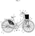
- the bicycle in which an embodiment of the present invention is used is a recreational bicycle, comprising a frame 1 with a double loop type of frame unit 2 and front fork 3; a handle component 4; a drive component 5; a front wheel 6; a rear wheel 7 provided with a four-speed integral shifting hub 10; front and rear brake devices 8 (only the front one is shown in the figure); and a shift control element 9 for conveniently operating the internal shifting hub 10.
- a bicycle speed sensor 12 furnished with a bicycle speed sensing lead switch is mounted on the front fork 3. This bicycle speed sensor 12 outputs a bicycle speed signal by sensing a magnet 13 mounted on the front wheel 6.
- the handle component 4 has a handle stem 14 that is fixed to the upper portion of the front fork 3, and a handlebar 15 that is fixed to the handle stem 14.
- Brake levers 16 and grips 17 that constitute part of the brake devices 8 are mounted at either end of the handlebar 15.
- a shift control element 9 is mounted on the right-side brake lever 16.
- the shift control element 9 has a control panel 20 formed integrally with the right-side (front-wheel) brake lever 16, two control buttons 21 and 22 disposed next to each other to the left and right on the lower portion of the control panel 20, a control dial 23 disposed above the control buttons 21 and 22, and a liquid-crystal display component 24 disposed to the left of the control dial 23.
- a shift control component 25 (Fig. 3) for controlling shifting operations is housed inside the control panel 20.
- the control buttons 21 and 22 are triangular push buttons.
- the control button 21 on the left side is a button for performing shifts to a higher speed step from a lower speed step
- the control button 22 on the right side is a button for performing shifts to a lower speed step from a higher speed step.
- the control dial 23, which is a dial for switching among three shifting modes and a parking mode (P), has four stationary positions: P, A1, A2 and M.
- the shift mode comprises an automatic shift 1 (A1) mode, an automatic shift 2 (A2) mode, and a manual shift (M) mode.
- the automatic shift 1 and 2 modes are for automatically shifting the internal shifting hub 10 by means of a bicycle speed signal from the bicycle speed sensor 12.
- the automatic shift 1 (A1) mode is a shift mode primarily used when automatic shifting is performed on level terrain
- the automatic shift 2 (A2) mode is a shifting mode primarily used when automatic shifting is performed on a slope.
- the automatic shift 2 (A2) mode is therefore set such that the shift timing for upshifts is faster than in the automatic shift 1 (A1) mode, whereas the shift timing for downshifts is slower than in the automatic shift 1 (A1) mode.
- the manual shift mode is for shifting the internal shifting hub 10 through the operation of the control buttons 21 and 22.
- the parking mode is for locking the internal shifting hub 10 and controlling the rotation of the rear wheel 7.
- the current riding speed is also displayed on the liquid-crystal display component 24, as is the speed step selected at the time of the shift.
- the shift control component 25 comprises a microcomputer consisting of a CPU, a RAM, a ROM, and an I/O interface. As shown in Fig. 3, the shift control component 25 is connected to the bicycle speed sensor 12, an actuation position sensor 26 composed of a potentiometer (for example, a potentiometer that senses the actuation position of the internal shifting hub 10), the control dial 23, and the control buttons 21 and 22.
- the shift control component 25 is also connected to a power supply 27 (consisting of a battery), a motor driver 28, the liquid-crystal display component 24, a memory component 30, and other input/output components.
- a shift motor 29 is connected to the motor driver 28.
- the memory component 30 is composed of EEPROM or another type of rewritable nonvolatile memory.
- Various types of data such as the password (PW) described below or the tire diameter, are sotred in the memory component.
- Also stored are six types of speed group data (hereinafter speed tables") expressing respective relations between each speed step and the speeds during the automatic shift 1 (A1) mode and the automatic shift 2 (A2) mode.
- the shift control component 25 controls the motor 29 according to the various modes, and also controls the display of the liquid-crystal display component 24.
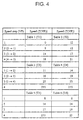
- Fig. 4 depicts examples of the six speed tables used during the automatic shift 1 (A1) mode.
- table 1 is a speed table containing a set speed (third gear) that corresponds to the downshifted speed steps achieved when the upshift mode described below has been set during the automatic shift 1 (A1) mode
- table 2 is a speed table containing a speed (second gear) that has been set during a regular downshift.
- Table 3 is a speed table containing a speed (first gear) that has been set during a regular upshift
- table 4 is a speed table containing a set speed (fourth gear) achieved during an upshift when the downshift mode described below has been set.
- table 5 ist a speed table containing a set speed (sixth gear) achieved when the downshift mode is canceled
- tabel 6 is a speed table containing a set speed (fifth gear) achieved when the upshift mode is canceled.
- the speed tables for the automatic shift 2 (A2) mode are not shown, the values in these tables tend to be lower overall than the corresponding speeds shown in Fig. 4.
- the speed data are merely examples, and the numerical values thereof are not limited in any way.
- the drive component 5 has a gear crank 18 that is provided to the lower portion (bottom bracket portion) of the frame body 2, a chain 19 that is wrapped around the gear crank 18, and the internal gear hub 10.
- the internal gear hub 10 primarily has a hub axle 41 that is fixed to the rear portion of the bicycle frame 1, a driver 42 that is located farther around the outer periphery at one end of the hub axle 41, a hub shell 43 that is located around the outer periphery of the hub axle 41 and driver 42, a planet gear mechanism 44 for transmitting motive power between the driver 42 and the hub shell 43, and an antiheft device 85.
- the planet gear mechanism 44 is made up of a total of four steps, one direct and three speed-increasing.
- the driver 42 is a roughly cylindrical member, one end of which is rotatably supported by the hub axle 41 via balls 45 and a hub cone 46.
- a hub cog 47 is fixed as an input elment around the outer periphery at one end.
- a notch 42a that expands outward in the radial direction from the space in the center is formed in the driver 42. Three of these notches 42a are formed at roughly equal angles in the circumferential direction.
- the hub shell 43 is a cylindrical member having a plurality of steps in the axial direction, and the driver 42 is housed in a housing space 43a around the inner periphery thereof.
- One side of the hub shell 43 is rotatably supported around the outer periphery of the driver 42 via balls 50, and the other by the hub axle 41 via balls 51 and a hub cone 52.
- Flanges 53 and 54 for supporting the spokes 7a (Fig. 1) of the rear wheel 7 are fixed around the outer periphery at both ends of the hub shell 43.
- a cover 55 is fixed to the outer side wall at one end of the driver 42, and the distal end of the cover 55 extends so as to cover the outer peripheral surface at one end of the hub shell 43.
- a sealing member 56 is positioned between the inner peripheral surface at the distal end of the cover 55, and the outer peripheral surface of the hub shell 43.
- the planet gear mechanism 44 is housed in the housing space 43a inside the hub shell 43, and has first, second, and third sun gears 60, 61, and 62, three planet gears 63 (only one planet gear is shown in the figures) that mesh with these, and a ring gear 64.
- the sun gears 60 to 62 are lined up in the axial direction around the inner periphery of the driver 42 and the outer periphery of the hub axle 41, and are allowed to rotate relative to the hub axle 41.
- the planet gears 63 are rotatably supported via a support pin 65 within the notches 42a in the driver 42.
- a first gear 63a, a second gear 63b, and a third gear 63c are formed integrally with the planet gears 63.
- the first gear 63a meshes with the first sun gear 60
- the second gear 63b meshes with the second sun gear 61
- the third gear 63c meshes with the third sun gear 62.
- the ring gear 64 is located on the outer peripheral side of the planet gears 63, and inner teeth are formed around the inner periphery. This ring gear 64 meshes with the second gear 63b of the planet gears 63.
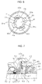
- a pair of stopping protrusions 41 a are formed at the locations where the sun gears 60 to 62 (sun gear 60 alone is shown in Fig. 6) are disposed around the external peripheral section of the hub axle 41.
- four housing spaces 60a to 62a are formed apart from each other in the peripheral direction around the inner periphery of the sun gears 60 to 62.
- a selective clutch mechanism 70 for preventing the sun gears 60 to 62 from performing relative rotation in the forward direction or for allowing them to rotate relative to the hub axle 41, and an actuation mechanism 91 for actuating the selective clutch mechanism 70, as shown in Fig. 5.
- the selective clutch mechanism 70 has a function whereby it selectively links one of the three sun gears 60 to 62 to the hub axle 41, and a function whereby it does not link any of the sun gears 60 to 62 to the hub axle 41.
- the selective clutch mechanism 70 has a plurality of drive pawls 71, 72, and 73 whose distal ends can mesh with the stopping protrusions 41a of the hub axle 41, and has annular wire springs 74, 75, and 76 for energizing the distal ends of the drive pawls 71 to 73 toward the hub axle 41.
- the drive pawls 71 to 73 are disposed in two out of the four spaces 60a to 62a for the corresponding sun gears 60 to 62, are swingably supported at their base ends in the facing spaces 60a to 62a, and are able to mesh at their distal ends with the stopping protrusions 41a.
- the sun gears 60 to 62 are no longer able to rotate in the forward direction (clockwise in Fig. 6) in relation to the hub axle 41 but can perform relative rotation in the opposite direction (counterclockwise in Fig. 6).
- the drive pawls are released, relative rotation is possible in both directions.
- the actuation mechanism 91 has a sleeve 77.
- the sleeve 77 is rotatably fitted over the outer periphery of the hub axle 41, and has a plurality of drive cam components 94a at the locations where the drive pawls 71 to 73 are disposed on the outer periphery.
- These drive cam components 94a strike any of the drive pawls 71 to 73, the struck pawls are raised, and the linkage between the hub axle 41 and the sun gears 60 to 62 is released by these pawls.
- An operator 78 is fixed to one end of the sleeve 77, and the sleeve 77 can be rotated by the rotation of the operator 78. The rotation of the sleeve 77 then causes the drive cam components 94a to selectively actuate the drive pawls 71 to 73, so that the linkage of the sun gears 60 to 62 with the hub axle 41 is controlled.
- a reduction mechanism 95 is linked to the operator 78.
- the reduction mechanism 95 reduces the speed of rotation of the shift motor 29, and transmits it to the operator 78.
- a large speed-increasing power transmission path (corresponds to shift position V4) with the largest speed increasing ratio is created when the drive pawl 71 strikes a stopping protrusion 41a of the hub axle 41, and the first sun gear 60 is selected; a medium speed-increasing power transmission path (corresponds to shift position V3) with the second-largest speed increasing ratio is created when the second sun gear 61 is selected; and a small speed-increasing power transmission path (corresponds to shift position V2) with the smallest speed increasing ratio is created when the third sun gear 62 is selected. If none of the sun gears has been selected, then a direct-coupled power transmission path (corresponds to shift position V1) is created.
- a first one-way clutch 80 is provided between the inner peripheral surface of the hub shell 43 and the outer peripheral surface at the other end of the driver 42.
- a second one-way clutch 81 is provided between the inner peripheral surface of the hub shell 43 and the outer peripheral surface of the ring gear 64.
- These one-way clutches 80 and 81 are both roller-type, one-way clutches that make it possible to reduce noise during idle running when a shift is made, to soften the shock when a shift is made, and to perform smoother shifting.
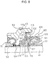
- the antitheft device 85 is provided to the left end (in Fig. 5) of the hub axle 41 within the hub shell 43. As shown in Fig s. 7 to 10, the antitheft device 85 has a spring washer 101 that rotates integrally with the sleeve 77, a moving cam 102, a moving member 103, a moving spring 104, and a lock ring 114.
- the moving cam 102 is nonrotatably installed while allowed to move axlially in relation to the hub axle 41.
- the moving member 103 presses against the moving cam 102.
- the moving spring 104 is disposed in a compressed state between the moving member 103 and a hub cone 52.
- the lock ring 114 is pressed against the moving member 103.
- the spring washer 101 is a member that is nonrotatably stopped by the sleeve 77, and has around its outer periphery an engagement tab 105 that strikes the moving cam 102.
- the moving cam 102 has a cylindrical cam body 106 and a stopping washer 107 that stops the cam body 106 and the hub axle 41 such that they can move in the axial direction but cannot rotate.
- a cam component 108 that strikes the engagement tab 105 is formed at the right end (in Fig. 9) of the cam body 106.
- the cam component 108 is formed such that the cam body 106 is moved axilally to the right only when the sleeve 77 rotates toward the locked position PK.
- the moving member 103 has a disk-shaped flange component 115 and a cylindrical component 116 integrally formed along the inner periphery of the flange component 115.
- a step 115a is formed on the flange component 115 in its mid-portion, as viewed in the radial direction.
- the lock ring 114 is rotatably supported by the step 115a.
- respective radial irregularities 114a are formed on that surface of the flange component 115 which faces the lock ring 114 and on that surface of the lock ring 114 which faces the flange component 115.
- Serration teeth 114b are formed in the outer peripheral portion of the lock ring 114. These serration teeth 114b can engage with serration teeth 113 formed in the inner peripheral surface of the hub shell 43.
- protrusions 116a are formed on the inner peripheral surface of the cylindrical component 116, as shown in Fig. 10.
- the protrusions 116a engage four grooves 41b formed in the outer peripheral surface of the hub axle 41.
- a thread and a stopping groove are formed in the outer peripheral surface of the cylindrical component 116.
- a pressure ring 117 is mounted around the outside of the cylindrical component 116, as shown in Fig. 7.
- the pressure ring 117 which is nonrotatably supported on the cylindrical component 116 while allowed to move in the axial direction, is allowed to come into contact with the lock ring 114.
- a pressure nut 118 is screwed on the outer periphery at the right end of the cylindrical component 116.
- a coned disk spring 119 is disposed between the pressure nut 118 and the pressure ring 117.
- the pressure exerted by the coned disk spring 119 can be adjusted by adjusting the fastening of the pressure nut 118; the frictional force between the lock ring 114 and the flange component 115 of the moving member 103 can be adjusted via the pressure ring 117; and the rotation of the hub shell 43 can be controlled arbitrarily.
- maximizing the frictional force produced by the coned disk spring 119 makes it possible to bring the hub shell 43 into a locked state.
- reducing the frictional force weakens the force with which the rotation of the hub shell 43 is controlled and allows the hub shell 43 to rotate in relation to the hub axle 41.
- a frictional force is generated when the coned disk spring 119 is energized, and the rotation is controlled, unlike in a free-rotating state.
- This embodiment allows the rotation of the hub shell 43 (that is, the rotation of the rear wheel 7) to be freely controlled by adjusting the energizing force of the coned disk spring 119 within a range that extends essentially from a locked state to a free-rotating state.
- Shifting and locking are performed by actuating the shift motor 29 through mode selection with the control dial 23 of the shift control element 9 and through shifting with the control buttons 21 and 22, and by rotating the sleeve 77 via the operator 78.
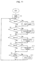
- Fig. 11 is a flow chart illustrating the control routine of the shift control component 25.
- step S1 When the power is turned on, initialization is performed in step S1.
- circumference data used for calculating speed is set to a diameter of 26 inches
- the speed step is set to the second gear (V2)
- various flags are reset.
- step S2 a decision is made as to whether the control dial 23 has been set to the parking mode.
- step S3 a decision is made as to whether the control dial 23 has been set to the automatic shift 1 mode.
- step S4 a decision is made as to whether the control dial 23 has been set to the automatic shift 2 mode.
- step S5 a decision is made as to whether the control dial 23 has been set to the manual shift mode.
- step S6 a decision is made as to whether some other routine, such as tire diameter input, has been selected.
- step S10 the dial P routine shown in Fig. 12 is executed.
- step S3 the automatic shift 1 routine shown in Figs. 14 and 15 is executed.
- step S4 the automatic shift 2 routine shown is executed in the same manner as the automatic shift 1 routine.
- step S13 the manual shift routine shown in Fig. 16 is executed.
- step S6 the operation proceeds from step S6 to step S14, and the selected routine is executed.
- step S10 a decision is made as to whether 30 seconds have elapsed since the dial was turned to position P in step S21 in Fig. 12.
- step S22 a decision is made as to whether a password PW has been registered. This decision is made on the basis of whether the password PW has already been stored in the memory component 30. If the password has already been registered, the operation proceeds to step S23.
- step S23 a decision is made as to whether the left control button 21 has been operated.
- the purpose of operating the control buttons 21 and 22 here is to enter the password for unlocking the locked internal shifting hub 10.
- step S24 a decision is made as to whether the right control button 22 has been operated.
- step S25 a decision is made as to whether the password LR entered by operation of the two control buttons 21 and 22 matches the registered password PW. If there is no match, the operation proceeds to step S26.
- step S26 a decision is made as to whether the password still does not match after it has been entered three times. If it has yet to be entered three times, the operation returns to step S23, and reentering of the password is permitted.
- step S27 the system waits for 10 minutes to pass, and when 10 minutes have elapsed, the operation returns to step S23, and reentering of the password is permitted.
- step S30 the shift motor 29 is driven by the motor driver 28, and the actuation position VP is set to the locked position PK.
- step S30 the shift motor 29 is driven by the motor driver 28, and the actuation position VP is set to the locked position PK.
- the sleeve 77 is rotated to the locked position via the operator 78.
- the engagement tab 105 of the spring washer 101 rotating together with the sleeve 77 moves into the cam component 108a when the sleeve 77 is rotated from a shift position to the locked position PK.
- the moving cam 102 and the moving member 103 energized by the moving spring 104 move to the right from the position shown in Figs.
- the hub shell 43 is locked by being coupled directly with the hub axle 41, so the rotation of the hub shell 43 (rear wheel 7) is impeded even when an attempt is made to push the bicycle, making the bicycle more difficult to move and reducing the likelihood of a theft.
- step S31 the code registration routine illustrated in Fig. 13 is executed.
- a decision is made as to whether the control button 21 has been operated in step S41 in Fig. 13. If the control button 21 has been operated, the operation proceeds to step S42, and the left number L (a ten-digit number) is increased by one.
- step S43 a decision is made as to whether the control button 22 has been operated. The operation returns to step S41 until the control button 22 is pushed, and the left number L is increased by one.
- the operation proceeds to step S44, and the right number R (a one-digit number) is increased by one.
- step S45 a decision is made as to whether the control button 21 was operated again.
- the operation returns to step S43 until the control button 21 is operated, and the right number R is increased by one.
- the operation proceeds to step S46, and the inputted number LR is stored as the password PW in the memory component 30.
- a password PW is thus registered after being selected from among 100 two-digit numbers LR ranging from "00" to "99.”
- step S32 if it is decided in step S23 that the control button 21 was operated during unlocking.
- step S32 the left number L is increased by one, just as when the password was registered. If it is decided that the control button 22 was operated, the operation proceeds from step S24 to step S33.
- step S32 the right number R is increased by one, just as when the password was registered. If the entered number LR matches the password PW in step S25, the operation proceeds to step S34, and the actuation position VP is set to first gear V1.
- the sleeve 77 is rotated by the shift motor 29 and positioned at the first gear V1, releasing the engagement between the lock ring 1 14 and the serration teeth 113 of the hub shell 43.
- the rotation of the driver 42 is transmitted unchanged to the hub shell 43 via the first one-way clutch 80.
- step S11 With the automatic shift 1 routine of step S11, the actuation position VP is set to the speed step corresponding to the bicycle speed SP. When the position is different from this, shifts are made one gear at a time toward this.
- step S51 in Fig. 14 the actuation position VP of the actuation position sensor 26 is entered.
- step S52 the current bicycle speed S is entered based on the speed signal from the bicycle speed sensor 12.
- step S53 it is determined whether the currently bicycle speed S thus entered exceeds the cancel speed T6 (VP) at the actuation position VP indicating the current speed step in table 6.
- the upshift mode is a shift mode established when an upshift is made. Chattering, which involves rapidly alternating upshifts and downshifts, occurs when downshifts are performed at speeds close to those achieved following upshifts. Slower than usual downshifts are performed in the upshift mode to prevent this phenomenon.
- Table 1 (T1) is the speed table used in the upshift mode.
- the downshift mode is a shift mode established when a downshift is made. Faster than usual upshifts are performed in the downshift mode to prevent chattering during downshifts.
- Table 4 (T4) is the speed table used in the downshift mode.
- table 3 (T3) is used during a regular upshift
- table 2 (T2) is used during a downshift.
- the two tables 3 and 2 have faster upshift and downshift timing patterns than do tables 4 and 1.
- table 6 (T6) and table 5 (T5) are speed tables for canceling these upshift and downshift modes and returning to regular shift timing.
- step S54 if the bicycle speed S exceeds the cancel speed T6 (VP) of table 6.
- the upshift flag SU indicating that the operation has been set to the upshift mode is reset during step S54. This procedure is skipped if the bicycle speed S does not exceed the cancel speed T6 (VP) of table 6.
- step S55 it is determined whether or not the bicycle speed S is below a cancel speed T5 (VP) corresponding to a speed step of table 5.
- the operation proceeds to step S56 if the bicycle speed S is below the cancel speed T5 (VP) of table 5.
- the downshift flag SD indicating that the operation has been set to a downshift mode is reset during step S56. This procedure is skipped if the bicycle speed S exceeds the cancel speed T6 (VP) of table 6.
- step S57 it is determined whether or not the speed step corresponds to the first gear (whether or not the actuation position is V1). The operation proceeds to step S58 if the speed step corresponds to the first gear.
- step S58 it is determined whether or not the upshift flag SU has already been set up, that is, whether or not an upshift mode has been set. The operation proceeds to step S59 if the upshift mode has been established, and table 1 (T1) is selected as the downshift speed table. The operation proceeds to step S60 if the upshift mode has not been established, and table 2 (T2) is selected as the downshift speed table.
- step S61 It is determined during step S61 whether or not the current bicycle speed S is below a shift speed T (VP) corresponding to a speed step of the selected table. In other words, it is determined whether or not the bicycle speed S has dropped below the shift speed corresponding to the current speed step. If the bicycle speed S has dropped below the shift speed, the operation proceeds to step S62, a downshift flag is set up, a downshift mode is established, an upshift flag SU is set up, and the upshift mode is canceled. During step S63, the actuation position VP is reduced one level in order to downshift the speed step by one level, returning the operation to the main-routine in Fig. 11.
- step S61 proceeds from step S61 to the step S64 in Fig. 15 if the current bicycle speed S is equal to or greater than a shift speed T (VP)corresponding to a speed step of the selected table.
- step S64 it is determined whether or not the actuation position is V4, that is, whether or not the speed step corresponds to the fourth gear.
- the operation returns to the main routine if the speed step corresponds to the fourth gear.
- step S65 it is determined whether or not a downshift flag SD has already been set up, that is, whether the downshift mode has been established.
- step S66 If the downshift mode has been established, the operation proceeds to step S66, and table 4 (T4) is selected as an upshift speed table. If the downshift mode has not been established, the operation proceeds to step S67, and table 3 (T3) is selected as an upshift speed table.
- step S68 it is determined whether or not the current bicycle speed S exceeds a shift speed (VP) corresponding to a speed step of the selected table. In other words, it is determined whether or not the bicycle speed S has risen above the shift speed corresponding to the current speed step. If the bicycle speed S has risen above the shift speed, the operation proceeds to step S69, an upshift flag is set up, an upshift mode is estabtished, the downshift flag is reset, and the downshift mode is canceled.
- step S70 the actuation position VP is raised one level in order to upshift the speed step by one level, returning the operation to the main routine in Fig. 1 1.
- step S65 the operation proceeds to step S65 if it has been determined during step S57 that the speed step corresponds to the first gear.
- first gear V1 is initially established because of low speed when the automatic shift 1 routine is performed, that is, when the foot is placed on the pedal, and the bicycle starts moving. If no downshift mode has been established, table 3 is selected, and when bicycle speed S exceeds 11 Km/h, the speed is upshifted to second gear V2, and an upshift mode is established. If the step S then exceeds 14 km/h, the upshift mode is canceled on the basis of table 6. If the bicycle accelerates even further and the bicycle speed exceeds 16 km/h, the speed is upshifted to third gear V3 on the basis of table 3.
- table 1 is selected because the bicycle is still operating in an upshift mode, and no downshift is performed until the speed drops below 9 km/h.
- a shift causes the automatic shift 1 routine to enter an upshift mode or a downshift mode, and the shift timing is slowed down in accordance with table 4 or 1 until the speed is increased or reduced to the prescribed cancel speed specified by table 6 or 5, making it possible to prevent chattering even when the shift is made prematurely. Smooth speed switching can thus be accomplished with minimal discomfort.
- the bicycle when the first sun gear 60 is linked to the hub axle 41 by the shift motor 29, the bicycle is in fourth gear, the rotation provided from the hub cog 47 to the driver 42 is increased by the largest gear ratio (which is determined by the number of teeth on the first sun gear 60, the first gear 63a and second gear 63b of the planet gears 63, and the ring gear 64), and this rotation is transmitted to the hub shell 43 via the second one-way clutch 81.
- the largest gear ratio which is determined by the number of teeth on the first sun gear 60, the first gear 63a and second gear 63b of the planet gears 63, and the ring gear 64
- the bicycle When the second sun gear 61 is selected and linked to the hub axle 41, the bicycle is in third gear, the rotation of the driver 42 is increased by a medium (the second largest) gear ratio (which is determined by the number of teeth on the second sun gear 61, the second gear 63b of the planet gears 63, and the ring gear 64), and this rotation is transmitted to the hub shell 43 via the second one-way clutch 81.
- a medium (the second largest) gear ratio which is determined by the number of teeth on the second sun gear 61, the second gear 63b of the planet gears 63, and the ring gear 64
- the bicycle When the third sun gear 62 is selected and linked to the hub axle 41, the bicycle is in second gear, the rotation of the driver 42 is increased by the smallest gear ratio (which is determined by the number of teeth on the third sun gear 62, the second gear 63b and third gear 63c of the planet gears 63, and the ring gear 64), and this rotation is transmitted to the hub shell 43 via the second one-way clutch 81. If none of the sun gears 60 through 62 is selected, the first gear is engaged as described above, and the rotation of the driver 42 is transmitted directly to the hub shell 43.
- Unselected sun gears perform relative rotation in the opposite direction from the forward direction with respect to the hub axle 41.
- the driver 42 and the hub shell 43 perform relative rotation in the direction in which meshing with the first oneway clutch 80 is released.
- step S11 gear shifts are made one at a time by operation of the control buttons 21 and 22.
- step S71 in Fig. 16 the actuation position VP of the actuation position sensor 26 is entered.
- step S72 a decision is made as to whether the control button 21 has been operated.
- step S73 a decision is made as to whether the control button 22 has been operated.
- step S74 a decision is made as to whether the current actuation position VP is V4, which corresponds to the fourth gear.
- step S75 If the current actuation position VP is not V4, the operation proceeds to step S75, and the actuation position VP is moved one speed step higher, executing a one-step upshift. If the current actuation position VP is V4, this routine is skipped.
- step S76 a decision is made as to whether current actuation position VP is V1, which corresponds to the first gear. If the current actuation position VP is not V1, the operation proceeds to step S77, and the actuation position VP is moved one speed step lower, executing a one-step downshift. If the current actuation position VP is V1, this routine is skipped.
- the present embodiment thus allows an upshift mode and a downshift mode to be established for the automatic shift 1 routine, with shifting performed in accordance with a slower than usual timing pattern, and chattering prevented, until the speed is raised or lowered to a prescribed level when a shift is performed, making it possible to perform automatic shifting with minimal discomfort by means of a simple control procedure based on the use of speed alone without the use of acceleration.
- an upshift mode or a downshift mode is established when a shift is performed, the speed is changed to a gear different from the regular shift gear, and the pattern shift timing is altered.
- the pattern of shift timing is slowed down such that shifting is performed at lower speeds when a downshift is performed in the upshift mode, and at higher speeds when an upshift is performed in the downshift mode.
- Regular shift timing is accelerated.
- idle post-shifting can be reduced, and comfortable shifting can be performed in accordance with fast shift timing.
- comfortable shifting can be accomplished by a simple control procedure because the shift timing is established on the basis of speed alone.
Landscapes
- Engineering & Computer Science (AREA)
- Chemical & Material Sciences (AREA)
- Combustion & Propulsion (AREA)
- Transportation (AREA)
- Mechanical Engineering (AREA)
- Control Of Transmission Device (AREA)
Applications Claiming Priority (3)
| Application Number | Priority Date | Filing Date | Title |
|---|---|---|---|
| JP23204797 | 1997-08-28 | ||
| JP232047/97 | 1997-08-28 | ||
| JP23204797A JP3231006B2 (ja) | 1997-08-28 | 1997-08-28 | 自転車用変速制御装置 |
Publications (3)
| Publication Number | Publication Date |
|---|---|
| EP0899188A2 true EP0899188A2 (de) | 1999-03-03 |
| EP0899188A3 EP0899188A3 (de) | 2000-08-02 |
| EP0899188B1 EP0899188B1 (de) | 2006-06-14 |
Family
ID=16933143
Family Applications (1)
| Application Number | Title | Priority Date | Filing Date |
|---|---|---|---|
| EP98115940A Expired - Lifetime EP0899188B1 (de) | 1997-08-28 | 1998-08-24 | Steuerungseinrichtung für eine Fahrradgangschaltung |
Country Status (10)
| Country | Link |
|---|---|
| US (1) | US6146297A (de) |
| EP (1) | EP0899188B1 (de) |
| JP (1) | JP3231006B2 (de) |
| CN (1) | CN1303341C (de) |
| CZ (1) | CZ263598A3 (de) |
| DE (1) | DE69834873T2 (de) |
| PL (1) | PL328286A1 (de) |
| RU (1) | RU2190553C2 (de) |
| SK (1) | SK115798A3 (de) |
| TW (1) | TW408073B (de) |
Cited By (6)
| Publication number | Priority date | Publication date | Assignee | Title |
|---|---|---|---|---|
| US6367833B1 (en) | 2000-09-13 | 2002-04-09 | Shimano, Inc. | Automatic shifting control device for a bicycle |
| EP1103455A3 (de) * | 1999-11-24 | 2002-10-16 | Shimano Inc. | Motoreinheit mit integriertem Geschwindigkeitsmessaufnehmer für eine Fahrradantriebsnabe |
| EP1384659A2 (de) | 2002-07-24 | 2004-01-28 | Shimano Inc. | Steuervorrichtung für Fahrradcomputer und Verfahren |
| EP1424276A2 (de) * | 2002-11-28 | 2004-06-02 | Shimano Inc. | Elektronische Steuereinheit für ein Fahrrad |
| EP1362783A3 (de) * | 2002-05-14 | 2007-07-04 | Shimano Inc. | Verfahren und Vorrichtung zum Kontrollieren der Fahrradgetriebe |
| US10086906B2 (en) | 2015-01-14 | 2018-10-02 | Sram, Llc | Method and apparatus for controlling automatic gear-change processes of an electric gear-change apparatus of a bicycle |
Families Citing this family (41)
| Publication number | Priority date | Publication date | Assignee | Title |
|---|---|---|---|---|
| US6244415B1 (en) * | 1999-12-30 | 2001-06-12 | Shimano, Inc. | Motor controlled shift control device including an idler gear for a bicycle transmission |
| IT1320405B1 (it) * | 2000-06-06 | 2003-11-26 | Campagnolo Srl | Dispositivo di comando elettrico per un deragliatore motorizzato perbiciclette. |
| US6352486B1 (en) | 2001-01-12 | 2002-03-05 | Sram Corporation | Semi-automatic shifting system |
| JP3573723B2 (ja) * | 2001-06-29 | 2004-10-06 | 株式会社シマノ | 自転車用変速制御装置 |
| US6698307B2 (en) | 2001-10-23 | 2004-03-02 | Sram Corporation | Electronic shifter for a bicycle |
| JP3644633B2 (ja) * | 2001-11-21 | 2005-05-11 | 株式会社シマノ | 自転車用変速制御装置 |
| US20030100392A1 (en) * | 2001-11-23 | 2003-05-29 | Tadashi Ichida | Method and apparatus for shifting a bicycle transmission |
| JP3654868B2 (ja) * | 2002-02-21 | 2005-06-02 | 株式会社シマノ | 自転車用変速制御装置及び自転車用変速制御方法 |
| US6741045B2 (en) * | 2002-04-23 | 2004-05-25 | Shimano, Inc. | Bicycle control apparatus that communicates power and data over a single transmission path |
| US6781510B2 (en) | 2002-07-24 | 2004-08-24 | Shimano, Inc. | Bicycle computer control arrangement and method |
| ATE521530T1 (de) * | 2002-12-06 | 2011-09-15 | Campagnolo Srl | Elektronisch, servobetätigte fahrradgangschaltung und zugehöriges verfahren |
| ATE353814T1 (de) * | 2002-12-06 | 2007-03-15 | Campagnolo Srl | Elektronisch, servobetätigte fahrradgangschaltung und zugehöriges verfahren |
| DE10258282A1 (de) * | 2002-12-13 | 2004-07-08 | Walter Ag | CVD-Beschichtungsverfarhen für ZrBx CyNz-Schichten (x+y+z = 1) sowie beschichtetes Schneidwerkzeug |
| DE60314986T2 (de) * | 2003-05-05 | 2008-04-03 | Campagnolo S.R.L. | Elektronische servogestützte Fahrradgangschaltung |
| JP2005104258A (ja) * | 2003-09-30 | 2005-04-21 | Shimano Inc | 自転車用電装品ホルダー |
| JP2005297712A (ja) * | 2004-04-09 | 2005-10-27 | Shimano Inc | 自転車用変速制御装置及び制御方法 |
| JP4145839B2 (ja) * | 2004-06-29 | 2008-09-03 | 株式会社シマノ | 自転車用変速システム及び自転車 |
| US20060063624A1 (en) * | 2004-09-20 | 2006-03-23 | Darrell Voss | Transmission systems and methods |
| CN102226467B (zh) | 2005-12-09 | 2014-06-25 | 福博科知识产权有限责任公司 | 无级变速器 |
| EP1811202A1 (de) | 2005-12-30 | 2007-07-25 | Fallbrook Technologies, Inc. | Stufenloses Getriebe |
| US8056914B2 (en) | 2007-01-19 | 2011-11-15 | Russell John Kalil | Momentum management in a wheel such as a traction wheel under a changing load |
| ITMI20071181A1 (it) * | 2007-06-12 | 2008-12-13 | Campagnolo Srl | Metodo di controllo elettronico di un cambio di bicicletta e sistema elettronico per bicicletta |
| WO2009030115A1 (fr) * | 2007-08-31 | 2009-03-12 | Southwest University | Moyeu porte-came à variation de vitesse à adaptation automatique |
| US8996263B2 (en) | 2007-11-16 | 2015-03-31 | Fallbrook Intellectual Property Company Llc | Controller for variable transmission |
| EP2088071B1 (de) * | 2008-02-06 | 2013-12-11 | Campagnolo S.r.l. | Verfahren zur elektronischen Steuerung eines Fahrradschalthebels und elektronisches System für ein Fahrrad |
| US9327792B2 (en) | 2011-01-28 | 2016-05-03 | Paha Designs, Llc | Gear transmission and derailleur system |
| US10207772B2 (en) | 2011-01-28 | 2019-02-19 | Paha Designs, Llc | Gear transmission and derailleur system |
| US9033833B2 (en) | 2011-01-28 | 2015-05-19 | Paha Designs, Llc | Gear transmission and derailleur system |
| CN102745299B (zh) * | 2011-04-18 | 2014-07-02 | 久鼎金属实业股份有限公司 | 助力自行车的变速控制系统 |
| US9651138B2 (en) | 2011-09-30 | 2017-05-16 | Mtd Products Inc. | Speed control assembly for a self-propelled walk-behind lawn mower |
| CN103373436A (zh) * | 2012-04-27 | 2013-10-30 | 邱金和 | 自动变速自行车的装置 |
| CN103895797B (zh) * | 2014-04-04 | 2016-04-27 | 太仓市悦博电动科技有限公司 | 内花鼓为旋转式的辅助动力自行车变速控制装置及控制方法 |
| US10046826B2 (en) * | 2015-08-27 | 2018-08-14 | Tektro Technology Corporation | Dual control lever and bicycle control assembly |
| US10047861B2 (en) | 2016-01-15 | 2018-08-14 | Fallbrook Intellectual Property Company Llc | Systems and methods for controlling rollback in continuously variable transmissions |
| US10023266B2 (en) | 2016-05-11 | 2018-07-17 | Fallbrook Intellectual Property Company Llc | Systems and methods for automatic configuration and automatic calibration of continuously variable transmissions and bicycles having continuously variable transmissions |
| WO2019025953A1 (en) | 2017-07-31 | 2019-02-07 | Pirelli Tyre S.P.A. | PNEUMATIC FOR BICYCLES |
| US11215268B2 (en) | 2018-11-06 | 2022-01-04 | Fallbrook Intellectual Property Company Llc | Continuously variable transmissions, synchronous shifting, twin countershafts and methods for control of same |
| US11174922B2 (en) | 2019-02-26 | 2021-11-16 | Fallbrook Intellectual Property Company Llc | Reversible variable drives and systems and methods for control in forward and reverse directions |
| JP7497214B2 (ja) * | 2020-05-29 | 2024-06-10 | 株式会社シマノ | 制御装置および変速システム |
| US11554832B2 (en) * | 2020-09-11 | 2023-01-17 | Shimano Inc. | Bicycle derailleur and method of controlling bicycle derailleur |
| CN114104186A (zh) * | 2021-12-09 | 2022-03-01 | 上海尚往网络科技有限公司 | 一种用于切换齿轮的方法、设备、介质及程序产品 |
Citations (1)
| Publication number | Priority date | Publication date | Assignee | Title |
|---|---|---|---|---|
| JPH08113131A (ja) | 1994-10-15 | 1996-05-07 | Aisin Seiki Co Ltd | 車両の制動制御装置 |
Family Cites Families (16)
| Publication number | Priority date | Publication date | Assignee | Title |
|---|---|---|---|---|
| CN1007226B (zh) * | 1985-10-09 | 1990-03-21 | 伊顿有限公司 | 自动变速器控制系统 |
| CN1028736C (zh) * | 1990-11-01 | 1995-06-07 | 吉林工业大学 | 电子控制机械式自动变速方法及装置 |
| IT1252262B (it) * | 1991-11-18 | 1995-06-08 | Catene Calibrate Regina | Cambio automatizzato per bicicletta |
| US5213548A (en) * | 1992-03-02 | 1993-05-25 | Colbert Ralph G | Gear shifting system for derailleur equipped bicycle |
| DE4212319A1 (de) * | 1992-04-13 | 1993-10-14 | Fichtel & Sachs Ag | Steuervorrichtung |
| US5261858A (en) * | 1992-06-19 | 1993-11-16 | Browning Automatic Transmission | Method and system for computer-controlled bicycle gear shifting |
| JP2593930Y2 (ja) * | 1993-06-16 | 1999-04-19 | 株式会社シマノ | 自転車用表示装置 |
| US5551315A (en) * | 1994-02-03 | 1996-09-03 | Pikoulas; George W. | Automatic gear changing system |
| JPH0826170A (ja) * | 1994-07-13 | 1996-01-30 | Akebono Brake Ind Co Ltd | 自動変速装置付自転車 |
| JPH08112181A (ja) * | 1994-10-12 | 1996-05-07 | Aasu Kk | 掛け布団、毛布等の襟カバ−装置 |
| JPH08113182A (ja) * | 1994-10-14 | 1996-05-07 | Akebono Brake Ind Co Ltd | 自動変速装置付自転車 |
| JPH08113183A (ja) * | 1994-10-14 | 1996-05-07 | Akebono Brake Ind Co Ltd | 自動変速装置付自転車 |
| US5514041A (en) * | 1994-11-21 | 1996-05-07 | Hsu; Yi-Hsung | Electronic bicycle derailleur control apparatus |
| IT1276417B1 (it) * | 1995-06-07 | 1997-10-31 | Campagnolo Srl | "dispositivo di cambio di velocita' per biciclette a controllo elettro nico" |
| US5599244A (en) * | 1995-08-14 | 1997-02-04 | Ethington; Russell A. | Automatic transmission shifter for velocipedes |
| CN1144171A (zh) * | 1995-08-25 | 1997-03-05 | 梅塞德斯-奔驰公司 | 汽车变速器自动换挡装置的操纵装置和操纵方法 |
-
1997
- 1997-08-28 JP JP23204797A patent/JP3231006B2/ja not_active Expired - Fee Related
-
1998
- 1998-08-19 CZ CZ982635A patent/CZ263598A3/cs unknown
- 1998-08-21 SK SK1157-98A patent/SK115798A3/sk unknown
- 1998-08-24 EP EP98115940A patent/EP0899188B1/de not_active Expired - Lifetime
- 1998-08-24 DE DE69834873T patent/DE69834873T2/de not_active Expired - Lifetime
- 1998-08-26 RU RU98116374/28A patent/RU2190553C2/ru not_active IP Right Cessation
- 1998-08-27 US US09/141,154 patent/US6146297A/en not_active Expired - Lifetime
- 1998-08-27 CN CNB981185169A patent/CN1303341C/zh not_active Expired - Fee Related
- 1998-08-28 TW TW087114289A patent/TW408073B/zh not_active IP Right Cessation
- 1998-08-28 PL PL98328286A patent/PL328286A1/xx unknown
Patent Citations (1)
| Publication number | Priority date | Publication date | Assignee | Title |
|---|---|---|---|---|
| JPH08113131A (ja) | 1994-10-15 | 1996-05-07 | Aisin Seiki Co Ltd | 車両の制動制御装置 |
Cited By (12)
| Publication number | Priority date | Publication date | Assignee | Title |
|---|---|---|---|---|
| EP1103455A3 (de) * | 1999-11-24 | 2002-10-16 | Shimano Inc. | Motoreinheit mit integriertem Geschwindigkeitsmessaufnehmer für eine Fahrradantriebsnabe |
| US6367833B1 (en) | 2000-09-13 | 2002-04-09 | Shimano, Inc. | Automatic shifting control device for a bicycle |
| US6454288B1 (en) | 2000-09-13 | 2002-09-24 | Shimano, Inc. | Automatic shifting control device for a bicycle |
| US6467786B2 (en) | 2000-09-13 | 2002-10-22 | Shimano, Inc. | Automatic shifting control device for a bicycle |
| EP1188661A3 (de) * | 2000-09-13 | 2006-04-26 | Shimano Inc. | Automatische Steuerungseinrichtung für eine Fahrradgangschaltung |
| EP1362783A3 (de) * | 2002-05-14 | 2007-07-04 | Shimano Inc. | Verfahren und Vorrichtung zum Kontrollieren der Fahrradgetriebe |
| EP1384659A2 (de) | 2002-07-24 | 2004-01-28 | Shimano Inc. | Steuervorrichtung für Fahrradcomputer und Verfahren |
| EP1384659A3 (de) * | 2002-07-24 | 2007-04-18 | Shimano Inc. | Steuervorrichtung für Fahrradcomputer und Verfahren |
| EP1424276A2 (de) * | 2002-11-28 | 2004-06-02 | Shimano Inc. | Elektronische Steuereinheit für ein Fahrrad |
| EP1424276A3 (de) * | 2002-11-28 | 2004-11-10 | Shimano Inc. | Elektronische Steuereinheit für ein Fahrrad |
| US7065434B2 (en) | 2002-11-28 | 2006-06-20 | Shimano, Inc. | Bicycle electronic control device with a reset function |
| US10086906B2 (en) | 2015-01-14 | 2018-10-02 | Sram, Llc | Method and apparatus for controlling automatic gear-change processes of an electric gear-change apparatus of a bicycle |
Also Published As
| Publication number | Publication date |
|---|---|
| CN1210213A (zh) | 1999-03-10 |
| JP3231006B2 (ja) | 2001-11-19 |
| EP0899188B1 (de) | 2006-06-14 |
| EP0899188A3 (de) | 2000-08-02 |
| CZ263598A3 (cs) | 1999-08-11 |
| RU2190553C2 (ru) | 2002-10-10 |
| CN1303341C (zh) | 2007-03-07 |
| JPH1159554A (ja) | 1999-03-02 |
| DE69834873D1 (de) | 2006-07-27 |
| SK115798A3 (en) | 1999-04-13 |
| TW408073B (en) | 2000-10-11 |
| DE69834873T2 (de) | 2006-11-23 |
| US6146297A (en) | 2000-11-14 |
| PL328286A1 (en) | 1999-03-01 |
Similar Documents
| Publication | Publication Date | Title |
|---|---|---|
| EP0899188A2 (de) | Steuerungseinrichtung für eine Fahrradgangschaltung | |
| EP0869054B1 (de) | Motorsteuerung für ein Fahrrad | |
| US7399244B2 (en) | Apparatus for controlling a bicycle gear shift device based on movement of the device | |
| US7730803B2 (en) | Switch designation apparatus for a bicycle control unit | |
| EP1518785B1 (de) | Schaltsteuerung für Fahrrad | |
| US6057657A (en) | Magnetically operated bicycle antitheft device | |
| EP0834685B1 (de) | Schalteinrichtung für ein Fahrradgetriebe | |
| US7166054B2 (en) | Bicycle internal hub transmission with increased bearing size | |
| US20040035233A1 (en) | Apparatus for controlling first and second bicycle transmissions | |
| US6877755B2 (en) | Shift control apparatus for a bicycle transmission that operates when signals are detected | |
| EP0876953B1 (de) | Naben-Innenschaltung für Fahrräder | |
| EP1424273B1 (de) | Fahrrad-Anti-Diebstahl-Steuerungsgerät, Gangschaltvorrichtung und Schaltsystem | |
| US6737956B1 (en) | Password registration device for a bicycle | |
| EP0895926B1 (de) | Antriebsnabe für Fahrrad |
Legal Events
| Date | Code | Title | Description |
|---|---|---|---|
| PUAI | Public reference made under article 153(3) epc to a published international application that has entered the european phase |
Free format text: ORIGINAL CODE: 0009012 |
|
| AK | Designated contracting states |
Kind code of ref document: A2 Designated state(s): DE FR GB IT NL |
|
| AX | Request for extension of the european patent |
Free format text: AL;LT;LV;MK;RO;SI |
|
| PUAL | Search report despatched |
Free format text: ORIGINAL CODE: 0009013 |
|
| AK | Designated contracting states |
Kind code of ref document: A3 Designated state(s): AT BE CH CY DE DK ES FI FR GB GR IE IT LI LU MC NL PT SE |
|
| AX | Request for extension of the european patent |
Free format text: AL;LT;LV;MK;RO;SI |
|
| 17P | Request for examination filed |
Effective date: 20000829 |
|
| AKX | Designation fees paid |
Free format text: DE FR GB IT NL |
|
| 17Q | First examination report despatched |
Effective date: 20031010 |
|
| GRAP | Despatch of communication of intention to grant a patent |
Free format text: ORIGINAL CODE: EPIDOSNIGR1 |
|
| GRAS | Grant fee paid |
Free format text: ORIGINAL CODE: EPIDOSNIGR3 |
|
| GRAA | (expected) grant |
Free format text: ORIGINAL CODE: 0009210 |
|
| AK | Designated contracting states |
Kind code of ref document: B1 Designated state(s): DE FR GB IT NL |
|
| PG25 | Lapsed in a contracting state [announced via postgrant information from national office to epo] |
Ref country code: NL Free format text: LAPSE BECAUSE OF FAILURE TO SUBMIT A TRANSLATION OF THE DESCRIPTION OR TO PAY THE FEE WITHIN THE PRESCRIBED TIME-LIMIT Effective date: 20060614 Ref country code: IT Free format text: LAPSE BECAUSE OF FAILURE TO SUBMIT A TRANSLATION OF THE DESCRIPTION OR TO PAY THE FEE WITHIN THE PRESCRIBED TIME-LIMIT;WARNING: LAPSES OF ITALIAN PATENTS WITH EFFECTIVE DATE BEFORE 2007 MAY HAVE OCCURRED AT ANY TIME BEFORE 2007. THE CORRECT EFFECTIVE DATE MAY BE DIFFERENT FROM THE ONE RECORDED. Effective date: 20060614 |
|
| REG | Reference to a national code |
Ref country code: GB Ref legal event code: FG4D |
|
| REF | Corresponds to: |
Ref document number: 69834873 Country of ref document: DE Date of ref document: 20060727 Kind code of ref document: P |
|
| RAP2 | Party data changed (patent owner data changed or rights of a patent transferred) |
Owner name: SHIMANO INC. |
|
| NLT2 | Nl: modifications (of names), taken from the european patent patent bulletin |
Owner name: SHIMANO INC. Effective date: 20060802 |
|
| NLV1 | Nl: lapsed or annulled due to failure to fulfill the requirements of art. 29p and 29m of the patents act | ||
| PLBE | No opposition filed within time limit |
Free format text: ORIGINAL CODE: 0009261 |
|
| STAA | Information on the status of an ep patent application or granted ep patent |
Free format text: STATUS: NO OPPOSITION FILED WITHIN TIME LIMIT |
|
| EN | Fr: translation not filed | ||
| 26N | No opposition filed |
Effective date: 20070315 |
|
| GBPC | Gb: european patent ceased through non-payment of renewal fee |
Effective date: 20060914 |
|
| PG25 | Lapsed in a contracting state [announced via postgrant information from national office to epo] |
Ref country code: GB Free format text: LAPSE BECAUSE OF NON-PAYMENT OF DUE FEES Effective date: 20060914 |
|
| PG25 | Lapsed in a contracting state [announced via postgrant information from national office to epo] |
Ref country code: FR Free format text: LAPSE BECAUSE OF FAILURE TO SUBMIT A TRANSLATION OF THE DESCRIPTION OR TO PAY THE FEE WITHIN THE PRESCRIBED TIME-LIMIT Effective date: 20070309 |
|
| PG25 | Lapsed in a contracting state [announced via postgrant information from national office to epo] |
Ref country code: FR Free format text: LAPSE BECAUSE OF FAILURE TO SUBMIT A TRANSLATION OF THE DESCRIPTION OR TO PAY THE FEE WITHIN THE PRESCRIBED TIME-LIMIT Effective date: 20060614 |
|
| PGFP | Annual fee paid to national office [announced via postgrant information from national office to epo] |
Ref country code: DE Payment date: 20150818 Year of fee payment: 18 |
|
| REG | Reference to a national code |
Ref country code: DE Ref legal event code: R119 Ref document number: 69834873 Country of ref document: DE |
|
| PG25 | Lapsed in a contracting state [announced via postgrant information from national office to epo] |
Ref country code: DE Free format text: LAPSE BECAUSE OF NON-PAYMENT OF DUE FEES Effective date: 20170301 |