EP0897864A2 - Vorrichtung und Verfahren zum dosierten Abfüllen von flüssigen bis pastösen Produkten - Google Patents
Vorrichtung und Verfahren zum dosierten Abfüllen von flüssigen bis pastösen Produkten Download PDFInfo
- Publication number
- EP0897864A2 EP0897864A2 EP98111827A EP98111827A EP0897864A2 EP 0897864 A2 EP0897864 A2 EP 0897864A2 EP 98111827 A EP98111827 A EP 98111827A EP 98111827 A EP98111827 A EP 98111827A EP 0897864 A2 EP0897864 A2 EP 0897864A2
- Authority
- EP
- European Patent Office
- Prior art keywords
- container
- filling
- product
- containers
- lifting plate
- Prior art date
- Legal status (The legal status is an assumption and is not a legal conclusion. Google has not performed a legal analysis and makes no representation as to the accuracy of the status listed.)
- Granted
Links
Images


Classifications
-
- B—PERFORMING OPERATIONS; TRANSPORTING
- B65—CONVEYING; PACKING; STORING; HANDLING THIN OR FILAMENTARY MATERIAL
- B65B—MACHINES, APPARATUS OR DEVICES FOR, OR METHODS OF, PACKAGING ARTICLES OR MATERIALS; UNPACKING
- B65B3/00—Packaging plastic material, semiliquids, liquids or mixed solids and liquids, in individual containers or receptacles, e.g. bags, sacks, boxes, cartons, cans, or jars
- B65B3/26—Methods or devices for controlling the quantity of the material fed or filled
- B65B3/30—Methods or devices for controlling the quantity of the material fed or filled by volumetric measurement
- B65B3/32—Methods or devices for controlling the quantity of the material fed or filled by volumetric measurement by pistons co-operating with measuring chambers
- B65B3/326—Methods or devices for controlling the quantity of the material fed or filled by volumetric measurement by pistons co-operating with measuring chambers for dosing several products to be mixed
-
- B—PERFORMING OPERATIONS; TRANSPORTING
- B65—CONVEYING; PACKING; STORING; HANDLING THIN OR FILAMENTARY MATERIAL
- B65B—MACHINES, APPARATUS OR DEVICES FOR, OR METHODS OF, PACKAGING ARTICLES OR MATERIALS; UNPACKING
- B65B43/00—Forming, feeding, opening or setting-up containers or receptacles in association with packaging
- B65B43/42—Feeding or positioning bags, boxes, or cartons in the distended, opened, or set-up state; Feeding preformed rigid containers, e.g. tins, capsules, glass tubes, glasses, to the packaging position; Locating containers or receptacles at the filling position; Supporting containers or receptacles during the filling operation
- B65B43/54—Means for supporting containers or receptacles during the filling operation
- B65B43/60—Means for supporting containers or receptacles during the filling operation rotatable
- B65B43/62—Means for supporting containers or receptacles during the filling operation rotatable about an axis located at the filling position, e.g. the axis of the container or receptacle
-
- B—PERFORMING OPERATIONS; TRANSPORTING
- B65—CONVEYING; PACKING; STORING; HANDLING THIN OR FILAMENTARY MATERIAL
- B65B—MACHINES, APPARATUS OR DEVICES FOR, OR METHODS OF, PACKAGING ARTICLES OR MATERIALS; UNPACKING
- B65B59/00—Arrangements to enable machines to handle articles of different sizes, to produce packages of different sizes, to vary the contents of packages, to handle different types of packaging material, or to give access for cleaning or maintenance purposes
- B65B59/04—Machines constructed with readily-detachable units or assemblies, e.g. to facilitate maintenance
-
- B—PERFORMING OPERATIONS; TRANSPORTING
- B65—CONVEYING; PACKING; STORING; HANDLING THIN OR FILAMENTARY MATERIAL
- B65B—MACHINES, APPARATUS OR DEVICES FOR, OR METHODS OF, PACKAGING ARTICLES OR MATERIALS; UNPACKING
- B65B39/00—Nozzles, funnels or guides for introducing articles or materials into containers or wrappers
- B65B2039/009—Multiple outlets
Definitions
- the invention relates first to a device according to the preamble of Claim 1.
- Such a device for filling different products comes from the German utility model step 295 12 257.
- the product is fed either via a so-called rotary feeder with a fixed Container or in a modified version in that the multiple dose stands firm and the container at least during the filling process around the essentially vertical adjustment axis is rotated. No matter how the products are filled in in any case, these pass through vertically downward flow channels in the Multiple dose in the container.
- the supply of one product to the control sleeve the multiple dispenser is indicated in the form of a horizontally running line.
- German patent 42 26 566 is also a device for dosing and Filling of liquid or pasty products has become known, using the containers, such as plastic cups with different products, such as. B. Fruit yoghurt of different flavors for an assortment packaging can be filled.
- the containers such as plastic cups with different products, such as. B. Fruit yoghurt of different flavors for an assortment packaging can be filled.
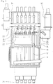
- the respective product is made from one own product container via feed lines and distribution pipes to the respective Single batchers fed to the web series, whereby one product can also be used for several e.g. B. two-row series can be supplied. This means that for a total of eight Lane rows four product containers with different product variants are available can.
- the invention has for its object a device of the type mentioned to create, which without any significant change for the filling of a Single product over several individual doses as well as for the filling of several Place the products in a common, precisely aligned container can and especially when switching from a single product to a Multi-product filling and vice versa, especially with special turning mold fillings characterized by a diverse and flexible application. Furthermore, a Methods are proposed by which a particularly simple means largely trouble-free and clean filling of the containers, especially of Plastic containers is reached.
- this task is performed by the characteristic Features of claim 1 achieved.
- the means according to the invention one comes to a filling device, the conversion from a single product filling over several Single batchers in a multiple product filling via a common multiple batcher makes it particularly easy.
- Such a distributor element can, for example, according to the features of claim 2 be designed.
- a switch from one to the other filling option is particularly successful easy and simple if the features according to claim 3 are realized.
- the Multiple doser at least as far as its product inlet side is concerned, is arranged lower than the distributor elements in such a way that that of the distributor elements of Single dispensers leading to the ring grooves in the control sleeve on the multiple dispenser Point the supply lines essentially at an angle downwards.
- the special arrangements contribute to an unimpeded flow the ring grooves of the control sleeve with an axial distance from each other and that of Through openings in the housing and the flow channels of the multiple dispenser one special importance in.
- the plunger has passage channels free guide pins are guided in the longitudinal bores and the plunger each one in the area of the ring grooves, which cooperate with the passage openings Show tax union.
- the plungers are designed as a closure member with a cutter.
- the pump drives assigned to the individual dosers and control valve drives for generating the volume or the respective Quantity related to freely selectable product streams or strands by assigned power-adjustable servomotors can be driven, if necessary with a Control device, such as a programmable logic controller are coupled, so that the ratio of the quantities fed to the outlet openings of the multiple dispenser Product streams or strands, possibly according to a predetermined recipe, is changeable.
- a Control device such as a programmable logic controller
- each container is formed within the meaning of claim 14.
- Such a method ensures that no disruptive or inaccessible Corners, columns or the like in the area of the holding device that could be contaminated by an uncontrolled overflow of the product or become inoperable. This is also after long use of the device a perfect function with regard to the exact alignment of the filling Container ensured. It is important above all that at least during the Filling the containers securely held in the holding device and after the Filling can be released automatically from this. Additional actuators can be completely eliminated.
- the twisting also enables simplified cleaning when e.g. B. from above Cleaning liquid emerging from the movement path of the cell sheets arranged spray nozzles is directed onto the clamping ring or lifting plate.
- each of the conveying means indicated in FIG. 1 there are cell sheets lying one behind the other 1 arranged, which can be driven circumferentially in the direction of the arrow.
- the Cell sheets are each in pairs extending transversely to the transport direction 2
- Container receptacles 3 arranged in the container in a known manner, for example Cups 4 made of plastic can be used, so that from FIG. 3 can be seen from a container 4.
- a holding device if necessary in connection with a holding element 6, each can be conical Plastic cup 4 via a lifting device, not shown, into an upper one Fill position are raised, in the manner described in more detail below a product can be filled.
- the Container 4 After filling, the Container 4 is added via its edge region 7 in the cup receptacles 3, so that they are then transported in a certain step in the transport direction can. At a distance of the transport step or a multiple thereof, are above the cell sheets 1 arranged individual dispensers 8, each with its own Product container 9 are connected.
- the same product e.g. As yogurt
- 9 the same product, e.g. As yogurt, may be included, which over the individual dose 8 over a mouthpiece 10 shown in phantom in the drawing alternately in the in the container hanging from the cell sheets can be dispensed.
- the interchangeable or exchangeable mouthpieces can be normal nozzles with thread cutters act for fruits, lettuce or the like, as shown for example in FIG. 3 is shown at the bottom left.
- thread cutter nozzles of course other mouthpieces, e.g. B. nozzles for cream, liquids, etc. are used become.
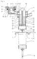
- the two product containers 9 each have a pump drive 11 and a rotary valve drive 12 assigned, with a pump piston 13 via the former and a pump piston via the latter Control valve 14 can be applied.
- the pump drive has one Metering housing 15 with a cylinder bore 16 for receiving a metering piston 17 and the rotary valve drive 12 has a cylinder bore 18 for a control slide trained control valve 14.
- the control valve 14 is the product inlet and the -process controlled. The product flow takes place via the mouthpiece used, e.g. B. the nozzle 10.
- the pump drive 11 has a drive shaft 19 on which an arm 21 a Arranged pair of toggle levers, the other arm 22 with the pump piston 13 in Connection is established.
- the drive shaft 19 is interposed a gear 23 arranged by a servo motor 24 which is not connected to a Program control shown in connection.
- To the rotary drive 12 of the Control valve 14 includes a control rod 25 (FIG. 5), which has a gear unit 26 is in drive connection with a separate servo motor 27.
- a common multiple dose 28 used which via a special distribution system 29 with the "normal" Mouthpieces liberate the discharge ends of the individual doses 8 in connection with them brought.
- a distributor element 31 which has a quick release device 32, for example a bayonet lock, on the underside of the single dose can be attached.
- An insert 39 with a T-shaped flange sits inside the distributor element 41, which is suspended in a corresponding annular recess 42 of the control valve 14 and one having a substantially angled flow channel 43 over the product via an opening 44 in the housing 35 into an inlet line 45 can flow in, which leads to a control sleeve 46.
- the control sleeve 46 surrounds the Doseur 28 at least partially and has annular grooves 47 and 48 which are in axial Are arranged at a distance from one another and with through openings 49, 51 Interact housing 52 of the multiple dose.
- the passage openings 49, 51 can finally with essentially vertical flow channels 53, 54 of the housing 52 are connected, in which plungers 55, 56 slidably are led.
- the ring channel 48 of the control sleeve 46 is diametrically opposite to the inlet line 45 via an inlet line 50 the single dose 8 located on the other side.
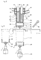
- the containers 4 are in the Cup receptacles 3 suspended, as can be seen from Figure 4.
- a lifting plate 57 is arranged, which on its the container facing end has a clamping ring 58 which together with the lifting plate 57 in an adjustment axis 59 adjustable in the vertical direction and by a not shown Rotary drive is rotatable about this adjustment axis 59.
- the containers can be placed in an overhead filling position (FIG. 4) bring in which the container with its edge region 7 on a shoulder surface 61 of the Multiple dosers or the control sleeve 46 arrive at the system and thus exactly be aligned.
- the container 4 in the clamping ring 58 in the sense a stable centering. After filling the lifting device with the Lift plate 57 lowered again until the container 4 again in the cup receptacles 3 Cell sheets 1 arrive. With a further downward movement, they finally release Containers from the clamping ring 58, then the cell sheets by one step can be forwarded.
- the example of stainless steel manufactured clamping ring 58 has in its bottom surface 62 obliquely outward Surfaces with grooves 63 on, in connection with openings 64 product residues or cleaning fluid can flow out.
- the clamping ring 58 has a cylindrical inner wall, which is at a distance to the bottom surface 62 on the open side of the clamping ring 58 into an extension 65 transforms. Due to the conical design of the plastic cup, for example trained container 4, a clamping surface 66 is formed on the clamping element Distance to the bottom surface 4 'of the container 4 in a soft tissue area of the container creates a clamping effect.
- the lifting plate 57 with the clamping ring 58 for the purpose of a helical or zigzag or other rotary product filling relative to the multiple dispenser 28 about the vertical adjustment axis 59 of the lifting plate 57 is rotated.
- the lifting plate 57 is connected to a rotary drive 67.
- the rotary shaft 69 receives with the interposition of cardan shafts 73, 74 their drive from a servo motor 75.
- the lifting device 70 for the lifting plate 57 results primarily from FIG. 9 and includes essentially a lifting frame 76 which, contrary to the illustration in FIG Double-step machines, in which two rows of cup receptacles in a cell sheet exist, is extended accordingly.
- A is used to drive the lifting frame 76 separate servo motor 77 with gear 78 and an articulated shaft 79 and one with it connected pivot shaft 81.
- One arm 82 of a pair of toggle levers sits on this, whose other arm 83 is articulated on the lifting frame 76.
- To achieve a synchronous Lifting movement of the lifting frame 76 is a second pivot shaft 77 with the first Swivel shaft 81 articulated via a linkage 84.
- FIG. 7 A modified embodiment of the lifting plate or the associated Clamping ring 58 is shown for example in FIG. 7.
- the inner wall of the clamping ring 58 up to the extension 65 in runs essentially vertically and thus with the conical peripheral wall of a Container 4 encloses an angle ⁇ is in the variant according to FIG.
- An annular bead 85 is provided on the inner wall of the clamping ring 58 in accordance with FIG. This can e.g. B. in cylindrical containers, for. B. glasses can be used especially if a rubber covering is also used.
- a spray nozzle 86 is provided which is activated when the lifting device in its lower position is rotated all around.
- the pump drives assigned to the individual dispensers 8 can control 11 and control valve drives 12 for generating the volume or respective quantity related to freely selectable product streams or strands of the respective associated servomotors 24, 27 are driven such that the quantity ratio of the product flows supplied to the outlet openings of the multiple dispenser 28 or strands, possibly according to a predetermined recipe, can be changed.
Landscapes
- Engineering & Computer Science (AREA)
- Mechanical Engineering (AREA)
- Basic Packing Technique (AREA)
- Filling Of Jars Or Cans And Processes For Cleaning And Sealing Jars (AREA)
- Supplying Of Containers To The Packaging Station (AREA)
Abstract
Description
- Figur 1
- eine Vorderansicht auf eine Behälterfüll- und -verschließmaschine im Bereich einer Abfüllstation mit einer Dosiereinrichtung,
- Figur 2
- einen im wesentlichen horizontalen Schnitt durch die Dosiereinrichtung in vergrößertem Maßstab,
- Figur 3
- einen Längsschnitt durch die Dosiereinrichtung in Verbindung mit einer Hubeinrichtung für die Behälter,
- Figur 4
- eine vergrößerte Darstellung eines Teils der Dosiereinrichtung mit Mehrfachdoseur und Hubeinrichtung für die Behälter und
- Figur 5
- eine schematische Darstellung einer Antriebseinrichtung eines Pumpen- und Steuerventilantriebs einer Behälterfüll- und -verschließmaschine.
- Figur 6
- eine Teildarstellung einer Fülleinrichtung für eine wendelförmige Produktabfüllung mit einer Hub- und Festhaltevorrichtung,
- Figur 7
- eine abgewandelte Ausführungsform der Festhaltevorrichtung,
- Figur 8
- einen Teil einer Füllmaschine mit Hub- und Festhaltevorrichtung und zugehöriger Antriebseinrichtung in einer schematischen Seitenansicht und
- Figur 9
- eine der Figur 8 entsprechende Darstellung in der Aufsicht.
Claims (16)
- Vorrichtung zum dosierten Abfüllen von flüssigen bis pastösen Produkten, inbesondere eine mehrbahnige Aseptikmaschine zum verdrehten Einfüllen von wenigstens zwei Strömen bzw. Strängen mindestens zweier unterschiedlicher Produkte, vorzugsweise Nahrungs- und Genußmittel in jeweils einen gemeinsamen Behälter, vorzugsweise einen Kunststoffbecher, mit einem schrittweise umlaufend angetriebenen Fördermittel mit sich quer zur Förderrichtung erstreckenden, Behälteraufnahmen aufweisenden Zellenblechen, einem entlang einer im wesentlichen vertikalen Verstellachse die Behälter in eine oben liegende Füllstellung anhebbaren und mindestens bis zur Ablage der Behälter in die Becheraufnahmen der Zellenbleche absenkbaren Hubteller und einer um die vertikale Verstellachse relativ zur Produkteinfüllung verdrehbaren Klemmeinrichtung für die Behälter sowie einem Mehrfachdoseur mit jeweils einem der abzufüllenden Produkte zugeordneten, längsverlaufenden Strömungskanal und einer das Gehäuse des Mehrfachdoseurs zumindest teilweise umgebenden Steuermuffe mit produktbezogenen Ringkanälen, die einerseits mit Zulaufleitungen und andererseits mit Durchtrittsöffnungen des Gehäuses verbunden sind, dadurch gekennzeichnet, daß die jeweils einem der Produkte zugeordneten, an der Steuermuffe (46) im wesentlichen diametral gegenüberliegend angeordneten Zulaufleitungen (45, 50) des Mehrfachdoseurs (28) unter Zwischenschaltung von jeweils einem Verteilerelement (31) und einer Verbindungseinrichtung (32) an die von einem Mundstück (10) befreite Austrittsseite von in einer Behälterlängsreihe im Abstand eines Transportschrittes des Fördermittels oder eines Mehrfachen davon angeordneten Einzeldoseuren (8) angeschlossen sind.
- Vorrichtung nach Anspruch 1, dadurch gekennzeichnet, daß das Verteilerelement (31) ein im wesentlichen topfförmiges Gehäuse (35) mit einem Spannflansch (34) für einen nachgiebigen Spannring (33) sowie ein Einsatzstück (39) aufweist, das über einen abgewinkelten Strömungskanal (43) und eine Durchtrittsöffnung (44) im Gehäuse (35) des Verteilerelements (31) mit der Zulaufleitung (45, 50) in Verbindung steht und über einen im wesentlichen T-förmigen Flansch (41) mit einer im Querschnitt entsprechend gehaltenen Ringausnehmung (42) am unteren Ende eines verdrehbaren Steuerventils des Einzeldoseurs (8) eingehängt ist.
- Vorrichtung nach Anspruch 1 oder 2, dadurch gekennzeichnet, daß das bei der Mehrfachdosierung zum Einsatz gelangende Verteilerelement (31) und die bei der Einzeldosierung verwendeten Mundstücke (10) auswechselbar ausgebildet und mittels einer Schnellspanneinrichtung (32), beispielsweise einem Bajonettverschluß, lösbar an einem Gehäuse (15) des Einzeldoseurs (8) anschließbar sind.
- Vorrichtung nach einem oder mehreren der Ansprüche 1 bis 3, dadurch gekennzeichnet, daß die von den Verteilerelementen (31) der Einzeldoseure (8) zu den Ringnuten (47, 48) in der Steuermuffe (45) am Mehrfachdoseur (28) führenden Zulaufleitungen (45, 50) im wesentlichen schräg nach unten weisen.
- Vorrichtung nach Anspruch 3, dadurch gekennzeichnet, daß die den unterschiedlichen Produkten zugeordneten Ringnuten (47, 48) der Steuermuffe (46) mit axialem Abstand zueinander angeordnet sind und über Durchtrittsöffnungen (49, 51) im Gehäuse (52) des Mehrfachdoseurs (28) und Stößel (55, 56) aufnehmende, Strömungskanäle (53, 54) bildende Längsbohrungen mit Produktauslaßöffnungen des Mehrfachdoseurs (28) in Verbindung stehen.
- Vorrichtung nach Anspruch 5, dadurch gekennzeichnet, daß die Stoßel (55, 56) über Durchlaßkanäle freilassende Führungszapfen (60) in den Längsbohrungen (53, 54) geführt sind und die Stößel (55, 56) jeweils einen im Bereich der Ringnuten (47, 48) liegenden, mit den Durchtrittsöffnungen (49, 51) zusammenwirkenden Steuerbund (55', 56') aufweisen.
- Vorrichtung nach einem der Ansprüche 5 oder 6, dadurch gekennzeichnet, daß die Stößel (55, 56) an ihrem den Produktauslaßöffnungen zugewandten unteren Ende als Verschlußorgan mit Abschneider ausgebildet sind und an ihren oberen, aus dem Gehäuse herausragenden Ende über eine Formschlußverbindung (55) zwecks einer Produktfreigabe und Produktabsperrung anhebenden und absenkenden Betätigungseinrichtung (56) verbunden sind.
- Vorrichtung nach Anspruch 1, dadurch gekennzeichnet, das den Einzeldoseuren (8) zugeordnete Pumpenantriebe (11) und Steuerventilantriebe (12) zur Erzeugung von auf das Volumen bzw. die jeweilige Menge bezogen frei wählbaren Produktströmen bzw. -strängen von jeweils zugeordneten leistungseinstellbaren Servomotoren (24, 27) antreibbar sind, die gegebenenfalls mit einer Regeleinrichtung, wie einer speicherprogrammierten Steuerung, gekoppelt sind, so daß das Mengenverhältnis der den Austrittsöffnungen des Mehrfachdoseurs (28) zugeführten Produktströme bzw. -stränge, gegebenenfalls nach einer vorgegebenen Rezeptur, veränderbar ist.
- Vorrichtung zum Füllen von jeweils in einer Behälteraufnahme von schrittweise umlaufend angetriebenen Zellenblechen gehaltenen Behältern, vorzugsweise Kunststoffbechern, mit wenigstens einem dünnflüssigen bis pastösen Produkt, insbesondere unter aseptischen Bedingungen, mittels eines Füllkopfes und eines relativ zu diesem entlang einer im wesentlichen vertikalen Verstellachse in eine oben liegende Füllstellung anhebbaren und in eine unten liegende Ruhestellung absenkbaren Hubtellers einer Hubvorrichtung mit einer Festhaltevorrichtung zum ausgerichteten Festhalten jedes einzelnen Behälters zumindest während des Füllvorgangs, dadurch gekennzeichnet, daß die Festhaltevorrichtung (5) ein auf die Form und/oder Abmessungen der jeweils abzufüllenden Behälter (4) abgestimmtes, zusammen mit dem Hubteller (57) der Hubvorrichtung verstellbares ringförmiges Zentrierelement (58) und der Füllkopf (28) eine mit dem Behälter (4) beim Füllvorgang zur Anlage gelangende Abstützung (61) aufweist.
- Vorrichtung nach Anspruch 9, dadurch gekennzeichnet, daß das Zentrierelement von einem Klemmring (58) und die Abstützung am Füllkopf (28) von einer im wesentlichen senkrecht zur Verstellachse (59) der Hubeinrichtung verlaufenden Schulterfläche (61) gebildet ist.
- Vorrichtung nach Anspruch 9 oder 10, dadurch gekennzeichnet, daß der Klemmring (58) eine sich nur teilweise über seine Innenwandung erstreckende Klemmfläche (66) aufweist, die von einer mit Abstand zu dessen Bodenfläche (62) nach innen weisenden Ringwulst (85) gebildet ist.
- Vorrichtung nach Anspruch 11, dadurch gekennzeichnet, daß die Klemmfläche an der Innenwandung des Klemmrings (58) bis auf eine Erweiterung (65) an der Einführseite der Behälter (4) sich vertikal erstreckt und dadurch mit der konischen Umfangswandung des Behälters einen Winkel (α) einschließt.
- Vorrichtung nach einem der Ansprüche 9 bis 12, dadurch gekennzeichnet, daß der Hubteller (57) mit einem Drehantrieb (67) in Verbindung steht.
- Verfahren zum Füllen von jeweils in einer Behälteraufnahme von schrittweise umlaufend angetriebenen Zellenblechen gehaltenen Behältern, vorzugsweise Kunststoffbechern, mit wenigstens einem dünnflüssigen bis pastösen Produkt, insbesondere unter aseptischen Bedingungen, mittels eines Füllkopfes und eines relativ zu diesem entlang einer im wesentlichen vertikalen Verstellachse anhebbaren und absenkbaren Hubtellers einer Hubvorrichtung mit Festhaltevorrichtung, wobei die Behälter durch die Hubeinrichtung der Zellenbleche aus der Behälteraufnahme in eine oben liegende Füllstellung angehoben, durch die Festhaltevorrichtung zumindest während des Füllvorgangs ausgerichtet festgehalten und nach der Befüllung und Aufheben der Festhaltewirkung durch die Hubeinrichtung wieder in die Behälteraufnahme der Zellenbleche abgesenkt werden, dadurch gekennzeichnet, daß jeder Behälter beim Anheben aus der Behälteraufnahme des Zellenblechs in die Füllstellung kurz vor Erreichen der Endstellung der Hubbewegung des Hubtellers mit seinem Behälterrand am Füllkopf abstützend zur Anlage gelangt und durch die dabei erzeugte Rückwirkkraft im Sinne einer zunehmend stärkeren Festhaltekraft bzw. Zentrierstabilität in die Festhaltevorrichtung eingedrückt wird, aus der nach Befüllung der Behälter bei der Abwärtsbewegung des Hubtellers der Hubeinrichtung jeder Behälter über seinen Behälterrand durch die entsprechend ausgebildete Behälteraufnahme des Zellenblechs zurückgehalten und danach bei weiterem Absenken des Hubtellers automatisch aus der Festhaltevorrichtung gezogen und freigegeben wird.
- Verfahren nach Anspruch 14, dadurch gekennzeichnet, daß der Behälter mit Abstand zu dessen Bodenwandung in einem vorzugsweise nachgiebigem Wandungsbereich (Weichteilbereich) des Behälters festgehalten wird.
- Verfahren nach Anspruch 14 oder 15, dadurch gekennzeichnet, daß jeder Behälter zumindest während des Füllvorgangs, vorzugsweise auch während eines Reinigungsvorgangs, um die Verstellachse des Hubtellers gedreht wird und während eines Reinigungsvorgangs zusätzlich mit einer Reinigungsflüssigkeit beaufschlagt wird.
Applications Claiming Priority (4)
| Application Number | Priority Date | Filing Date | Title |
|---|---|---|---|
| DE1997135621 DE19735621C2 (de) | 1997-08-18 | 1997-08-18 | Verfahren und Vorrichtung zum Füllen von jeweils in einer Behälteraufnahme von schrittweise umlaufend angetriebenen Zellenblechen umfangsrandig eingehängten Behältern, vorzugsweise Kunststoffbechern |
| DE1997135619 DE19735619A1 (de) | 1997-08-18 | 1997-08-18 | Vorrichtung zum dosierten Abfüllen von flüssigen bis pastösen Produkten, insbesondere eine mehrbahnige Aseptikmaschine |
| DE19735619 | 1997-08-18 | ||
| DE19735621 | 1997-08-18 |
Publications (3)
| Publication Number | Publication Date |
|---|---|
| EP0897864A2 true EP0897864A2 (de) | 1999-02-24 |
| EP0897864A3 EP0897864A3 (de) | 1999-07-07 |
| EP0897864B1 EP0897864B1 (de) | 2001-04-11 |
Family
ID=26039213
Family Applications (1)
| Application Number | Title | Priority Date | Filing Date |
|---|---|---|---|
| EP98111827A Expired - Lifetime EP0897864B1 (de) | 1997-08-18 | 1998-06-26 | Vorrichtung und Verfahren zum dosierten Abfüllen von flüssigen bis pastösen Produkten |
Country Status (6)
| Country | Link |
|---|---|
| US (1) | US5996652A (de) |
| EP (1) | EP0897864B1 (de) |
| JP (1) | JPH11115904A (de) |
| AT (1) | ATE200453T1 (de) |
| DE (1) | DE59800608D1 (de) |
| NO (1) | NO983399L (de) |
Cited By (2)
| Publication number | Priority date | Publication date | Assignee | Title |
|---|---|---|---|---|
| EP1851112A4 (de) * | 2005-02-23 | 2012-03-21 | Norden Machinery Ab | Fülldüse |
| WO2023180542A1 (de) * | 2022-03-25 | 2023-09-28 | Ampack Gmbh | Dosiervorrichtung zu einem dosieren von flüssigen oder pastösen produkten, insbesondere lebensmitteln, sowie produktionsmaschine mit einer derartigen dosiervorrichtung |
Families Citing this family (25)
| Publication number | Priority date | Publication date | Assignee | Title |
|---|---|---|---|---|
| US6213166B1 (en) | 2000-01-12 | 2001-04-10 | Patrick Thibiant | Apparatus and process for forming novel spiral compositions |
| US6695510B1 (en) * | 2000-05-31 | 2004-02-24 | Wyeth | Multi-composition stick product and a process and system for manufacturing the same |
| WO2002000029A1 (en) * | 2000-06-26 | 2002-01-03 | Societe Des Produits Nestle S.A. | Fermented milk product and process |
| DE10054834B4 (de) * | 2000-11-04 | 2006-05-18 | Hassia Verpackungsmaschinen Gmbh | Dosiervorrichtung |
| US20030039728A1 (en) * | 2001-08-21 | 2003-02-27 | Herrick James Peter | Device and method for on-demand dispensing of spoonable or drinkable food products having visual appearance of multi-components |
| FR2832124B1 (fr) * | 2001-11-15 | 2004-09-03 | Erca Formseal | Dispositif de distribution d'un produit liquide ou pateux |
| DE102004028423A1 (de) * | 2004-06-01 | 2005-12-22 | Campina Gmbh & Co. Kg | Anlage zum Befüllen von Nahrungsmittelbechern, Mehrfachdüse und Dessertprodukt |
| EP1827988A1 (de) | 2004-12-20 | 2007-09-05 | Elopak Systems Ag | Vorrichtung und verfahren zur gleichzeitigen abgabe von halbfesten produkten |
| DE102006015638A1 (de) * | 2006-04-04 | 2007-10-11 | Finnah Engineering Und Packaging Gmbh | Maschine zum Füllen von Bechern mit Nahrungs- und Genußmitteln |
| US20070263605A1 (en) * | 2006-04-26 | 2007-11-15 | Texas Instruments, Inc. | SMS-Initiated VoIP |
| US20080072535A1 (en) * | 2006-08-31 | 2008-03-27 | Mueller Martin J | Apparatus for filling containers |
| US8582280B2 (en) * | 2008-01-11 | 2013-11-12 | Sang Kyu Ryu | Foldable keyboard for portable computer |
| DE102011119455A1 (de) * | 2011-11-28 | 2013-05-29 | Robert Bosch Gmbh | Vorrichtung zum gleichzeitigen Füllen von mindestens zwei Nahrungsmitteln unterschiedlicher Beschaffenheit in einen Behälter |
| EP2639163B1 (de) * | 2012-03-15 | 2014-09-10 | Antonio Mengibar, S.A. | Verfahren und Vorrichtung zur Erzeugung eines Füllmusters zum Füllen von Behältern |
| DE102012205901A1 (de) * | 2012-04-11 | 2013-10-17 | Krones Ag | Mehrkomponenten-Füllmaschine zum Befüllen von Behältern mit Flüssigkeiten |
| PL2829477T3 (pl) * | 2013-07-24 | 2016-10-31 | Maszyna napełniająca rotacyjna | |
| DE102014011075B4 (de) * | 2014-07-30 | 2017-07-20 | Benhil Gmbh | Verfahren zur Verpackung von flüssigen oder pastösen Produkten sowie hierfür geeignete Verpackungsmaschine |
| DE102015204951A1 (de) * | 2015-03-19 | 2016-09-22 | Robert Bosch Gmbh | Füllvorrichtung |
| JP6134839B2 (ja) * | 2016-05-13 | 2017-05-24 | 株式会社ダイゾー | 複数内容物収納製品の製造方法 |
| US11998024B2 (en) | 2017-06-16 | 2024-06-04 | Conopco, Inc. | Process for filling a receptacle with frozen confection |
| BE1027167B1 (fr) * | 2019-04-02 | 2020-11-05 | V B S Sprl | Systeme de dosage multi-buses |
| WO2021070695A1 (ja) * | 2019-10-09 | 2021-04-15 | 長野オートメーション株式会社 | 液を供給する装置 |
| WO2022149041A1 (en) * | 2021-01-05 | 2022-07-14 | Societe Des Produits Nestle Sa | Apparatuses and methods for enclosing a filling in a food product |
| CN113830367B (zh) * | 2021-10-13 | 2023-04-28 | 汕头市昌华机械设备有限公司 | 一种立体中封袋的灌装生产线 |
| US12522389B2 (en) * | 2023-06-08 | 2026-01-13 | Packline Usa, Llc | Automatic food product filling device |
Family Cites Families (10)
| Publication number | Priority date | Publication date | Assignee | Title |
|---|---|---|---|---|
| US3172434A (en) * | 1961-08-08 | 1965-03-09 | Richard C Boucher | Apparatus for filling containers |
| DE1275438B (de) * | 1966-02-25 | 1968-08-14 | Karlsruhe Augsburg Iweka | Selbstzentrierender Halter fuer Tuben an einer Tubenfuell- und -schliessmaschine |
| DE2921236A1 (de) * | 1979-05-25 | 1980-12-04 | Bosch Gmbh Robert | Dosiervorrichtung zum keimfreien abmessen und abfuellen von fluessigem gut |
| EP0128963B1 (de) * | 1983-06-13 | 1987-09-09 | Societe Des Produits Nestle S.A. | Verfahren und Vorrichtung zur Herstellung von Lebensmittelportionen mit mehreren Lagen |
| US4729206A (en) * | 1984-11-08 | 1988-03-08 | General Foods Corporation | Method and apparatus for filling and packaging a flowable product |
| DE3718950A1 (de) * | 1987-06-05 | 1988-12-22 | Alcan Gmbh | Verfahren und vorrichtung zum fuellen von behaeltern mit teigigem fuellgut |
| DE3919913C1 (de) * | 1989-06-19 | 1990-04-26 | Benz & Hilgers Gmbh, 4000 Duesseldorf, De | |
| DE4226566C2 (de) * | 1992-08-12 | 1996-04-18 | Jagenberg Ag | Vorrichtung zum Dosieren und Abfüllen von flüssigen oder pastösen Produkten |
| GB9403485D0 (en) * | 1994-02-24 | 1994-04-13 | Cpc United Kingdom Limited | Dispensing means |
| DE29512257U1 (de) * | 1995-07-29 | 1995-10-05 | Hamba-Maschinenfabrik Hans A.Müller GmbH & Co KG, 42275 Wuppertal | Becherfüllwerk für Nahrungs- und Genußmittel, insbesondere für dünnflüssige bis pasteuse Molkerei- und Fettprodukte |
-
1998
- 1998-06-26 DE DE59800608T patent/DE59800608D1/de not_active Expired - Fee Related
- 1998-06-26 AT AT98111827T patent/ATE200453T1/de not_active IP Right Cessation
- 1998-06-26 EP EP98111827A patent/EP0897864B1/de not_active Expired - Lifetime
- 1998-07-23 NO NO983399A patent/NO983399L/no not_active Application Discontinuation
- 1998-08-17 JP JP10230564A patent/JPH11115904A/ja active Pending
- 1998-08-18 US US09/135,958 patent/US5996652A/en not_active Expired - Lifetime
Cited By (2)
| Publication number | Priority date | Publication date | Assignee | Title |
|---|---|---|---|---|
| EP1851112A4 (de) * | 2005-02-23 | 2012-03-21 | Norden Machinery Ab | Fülldüse |
| WO2023180542A1 (de) * | 2022-03-25 | 2023-09-28 | Ampack Gmbh | Dosiervorrichtung zu einem dosieren von flüssigen oder pastösen produkten, insbesondere lebensmitteln, sowie produktionsmaschine mit einer derartigen dosiervorrichtung |
Also Published As
| Publication number | Publication date |
|---|---|
| DE59800608D1 (de) | 2001-05-17 |
| EP0897864B1 (de) | 2001-04-11 |
| ATE200453T1 (de) | 2001-04-15 |
| NO983399D0 (no) | 1998-07-23 |
| JPH11115904A (ja) | 1999-04-27 |
| EP0897864A3 (de) | 1999-07-07 |
| NO983399L (no) | 1999-02-19 |
| US5996652A (en) | 1999-12-07 |
Similar Documents
| Publication | Publication Date | Title |
|---|---|---|
| EP0897864A2 (de) | Vorrichtung und Verfahren zum dosierten Abfüllen von flüssigen bis pastösen Produkten | |
| EP0754144B1 (de) | Ventil zum abfüllen von flüssigkeiten in verpackungen | |
| DE3543504A1 (de) | Fuellpumpe zum eindosieren von fluessigen bis pastoesen produkten | |
| DE3809855A1 (de) | Verfahren zum aseptischen bzw. sterilen abfuellen von fluessigem fuellgut in behaelter sowie vorrichtung zum durchfuehren dieses verfahrens | |
| DE3918504C2 (de) | Verschließmaschine umlaufender Bauart | |
| DE2504621A1 (de) | Duesenvorrichtung zur austeilung von sirup o.dgl. | |
| DE60310590T2 (de) | Verfahren und vorrichtung zum dosieren von flüssigen substanzen in behältern | |
| EP1657159A1 (de) | Verfahren zum Befüllen eines Behälters mit zumindest zwei flüssigen oder pastösen Produkten und Füllvorrichtung zur Durchführung des Verfahrens | |
| EP2738135B1 (de) | Füllorgan zum Befüllen eines Behälters mit einem Füllprodukt | |
| EP1403187A1 (de) | Verpackungsmaschine mit einer Reinigungsvorrichtung | |
| EP1100723A1 (de) | Füllventil für die befüllung von flachbeutelverpackungen | |
| WO2016008707A1 (de) | Füllsystem sowie verfahren zum betrieb eines solchen füllsystems | |
| EP0979393B1 (de) | Produktausgabevorrichtung mit bewegbaren Auffangbehältern | |
| EP0131904A2 (de) | Tauchfüller | |
| EP1521532A1 (de) | Vorrichtung zum einsetzen von stielen in formen zum herstellen von stielkonfekt | |
| DE19735621C2 (de) | Verfahren und Vorrichtung zum Füllen von jeweils in einer Behälteraufnahme von schrittweise umlaufend angetriebenen Zellenblechen umfangsrandig eingehängten Behältern, vorzugsweise Kunststoffbechern | |
| EP2788273B1 (de) | Füllmaschine | |
| DE19735619A1 (de) | Vorrichtung zum dosierten Abfüllen von flüssigen bis pastösen Produkten, insbesondere eine mehrbahnige Aseptikmaschine | |
| DE3638601A1 (de) | Aufschaeumvorrichtung zum verdraengen des restluftvolumens aus mit einem aufschaeumbaren fluessigen fuellgut gefuellten behaeltern, insbesondere flaschen | |
| DE19758543B4 (de) | Verfahren und Vorrichtung zum verdrehten Einfüllen von wenigstens zwei Strömen bzw. Strängen mindestens zweier unterschiedlicher pastöser Produkte, insbesondere unter aseptischen Bedingungen | |
| DE1803371A1 (de) | Verfahren und Vorrichtung zum vollstaendigen Entleeren eines mit einer viskosen oderpastenartigen Substanz angefuellten Behaelters | |
| EP0401510B1 (de) | Anlagen zum Befüllen von Verpackungen mit Füllgut | |
| DE69524237T2 (de) | Verpackungsmaschine | |
| DE2043281C3 (de) | Maschine zum Einsetzen von dosierten Mengen geschmolzenen thermoplastischen Kunststoffs in Verschlußkapseln o.dgl | |
| EP1184648B1 (de) | Ausgabevorrichtung für ein Produktbereitstellungssystem |
Legal Events
| Date | Code | Title | Description |
|---|---|---|---|
| PUAI | Public reference made under article 153(3) epc to a published international application that has entered the european phase |
Free format text: ORIGINAL CODE: 0009012 |
|
| AK | Designated contracting states |
Kind code of ref document: A2 Designated state(s): AT BE CH DE DK ES FI FR GB IT LI NL SE |
|
| AX | Request for extension of the european patent |
Free format text: AL;LT;LV;MK;RO;SI |
|
| RTI1 | Title (correction) | ||
| PUAL | Search report despatched |
Free format text: ORIGINAL CODE: 0009013 |
|
| AK | Designated contracting states |
Kind code of ref document: A3 Designated state(s): AT BE CH CY DE DK ES FI FR GB GR IE IT LI LU MC NL PT SE |
|
| AX | Request for extension of the european patent |
Free format text: AL;LT;LV;MK;RO;SI |
|
| 17P | Request for examination filed |
Effective date: 19990713 |
|
| 17Q | First examination report despatched |
Effective date: 20000112 |
|
| AKX | Designation fees paid |
Free format text: AT BE CH DE DK ES FI FR GB IT LI NL SE |
|
| GRAG | Despatch of communication of intention to grant |
Free format text: ORIGINAL CODE: EPIDOS AGRA |
|
| GRAG | Despatch of communication of intention to grant |
Free format text: ORIGINAL CODE: EPIDOS AGRA |
|
| GRAH | Despatch of communication of intention to grant a patent |
Free format text: ORIGINAL CODE: EPIDOS IGRA |
|
| GRAH | Despatch of communication of intention to grant a patent |
Free format text: ORIGINAL CODE: EPIDOS IGRA |
|
| GRAA | (expected) grant |
Free format text: ORIGINAL CODE: 0009210 |
|
| AK | Designated contracting states |
Kind code of ref document: B1 Designated state(s): AT BE CH DE DK ES FI FR GB IT LI NL SE |
|
| PG25 | Lapsed in a contracting state [announced via postgrant information from national office to epo] |
Ref country code: NL Free format text: LAPSE BECAUSE OF FAILURE TO SUBMIT A TRANSLATION OF THE DESCRIPTION OR TO PAY THE FEE WITHIN THE PRESCRIBED TIME-LIMIT Effective date: 20010411 Ref country code: IT Free format text: LAPSE BECAUSE OF FAILURE TO SUBMIT A TRANSLATION OF THE DESCRIPTION OR TO PAY THE FEE WITHIN THE PRESCRIBED TIME-LIMIT;WARNING: LAPSES OF ITALIAN PATENTS WITH EFFECTIVE DATE BEFORE 2007 MAY HAVE OCCURRED AT ANY TIME BEFORE 2007. THE CORRECT EFFECTIVE DATE MAY BE DIFFERENT FROM THE ONE RECORDED. Effective date: 20010411 Ref country code: GB Free format text: LAPSE BECAUSE OF FAILURE TO SUBMIT A TRANSLATION OF THE DESCRIPTION OR TO PAY THE FEE WITHIN THE PRESCRIBED TIME-LIMIT Effective date: 20010411 Ref country code: FR Free format text: LAPSE BECAUSE OF FAILURE TO SUBMIT A TRANSLATION OF THE DESCRIPTION OR TO PAY THE FEE WITHIN THE PRESCRIBED TIME-LIMIT Effective date: 20010411 Ref country code: FI Free format text: LAPSE BECAUSE OF FAILURE TO SUBMIT A TRANSLATION OF THE DESCRIPTION OR TO PAY THE FEE WITHIN THE PRESCRIBED TIME-LIMIT Effective date: 20010411 |
|
| REF | Corresponds to: |
Ref document number: 200453 Country of ref document: AT Date of ref document: 20010415 Kind code of ref document: T |
|
| REG | Reference to a national code |
Ref country code: CH Ref legal event code: EP |
|
| REF | Corresponds to: |
Ref document number: 59800608 Country of ref document: DE Date of ref document: 20010517 |
|
| PG25 | Lapsed in a contracting state [announced via postgrant information from national office to epo] |
Ref country code: BE Free format text: LAPSE BECAUSE OF NON-PAYMENT OF DUE FEES Effective date: 20010630 |
|
| PG25 | Lapsed in a contracting state [announced via postgrant information from national office to epo] |
Ref country code: SE Free format text: LAPSE BECAUSE OF FAILURE TO SUBMIT A TRANSLATION OF THE DESCRIPTION OR TO PAY THE FEE WITHIN THE PRESCRIBED TIME-LIMIT Effective date: 20010711 Ref country code: DK Free format text: LAPSE BECAUSE OF FAILURE TO SUBMIT A TRANSLATION OF THE DESCRIPTION OR TO PAY THE FEE WITHIN THE PRESCRIBED TIME-LIMIT Effective date: 20010711 |
|
| REG | Reference to a national code |
Ref country code: CH Ref legal event code: NV Representative=s name: TROESCH SCHEIDEGGER WERNER AG |
|
| NLV1 | Nl: lapsed or annulled due to failure to fulfill the requirements of art. 29p and 29m of the patents act | ||
| EN | Fr: translation not filed | ||
| GBV | Gb: ep patent (uk) treated as always having been void in accordance with gb section 77(7)/1977 [no translation filed] |
Effective date: 20010411 |
|
| PG25 | Lapsed in a contracting state [announced via postgrant information from national office to epo] |
Ref country code: ES Free format text: LAPSE BECAUSE OF FAILURE TO SUBMIT A TRANSLATION OF THE DESCRIPTION OR TO PAY THE FEE WITHIN THE PRESCRIBED TIME-LIMIT Effective date: 20011030 |
|
| BERE | Be: lapsed |
Owner name: BENHIL GASTI VERPACKUNGSMASCHINEN G.M.B.H. Effective date: 20010630 |
|
| PLBE | No opposition filed within time limit |
Free format text: ORIGINAL CODE: 0009261 |
|
| REG | Reference to a national code |
Ref country code: CH Ref legal event code: PUE Owner name: BENZ & HILGERS GMBH TRANSFER- GASTI VERPACKUNGSMAS Ref country code: CH Ref legal event code: PFA Free format text: BENHIL GASTI VERPACKUNGSMASCHINEN GMBH TRANSFER- BENZ & HILGERS GMBH |
|
| STAA | Information on the status of an ep patent application or granted ep patent |
Free format text: STATUS: NO OPPOSITION FILED WITHIN TIME LIMIT |
|
| 26N | No opposition filed | ||
| PGFP | Annual fee paid to national office [announced via postgrant information from national office to epo] |
Ref country code: DE Payment date: 20080820 Year of fee payment: 11 Ref country code: CH Payment date: 20080814 Year of fee payment: 11 |
|
| PGFP | Annual fee paid to national office [announced via postgrant information from national office to epo] |
Ref country code: AT Payment date: 20080814 Year of fee payment: 11 |
|
| REG | Reference to a national code |
Ref country code: CH Ref legal event code: PL |
|
| PG25 | Lapsed in a contracting state [announced via postgrant information from national office to epo] |
Ref country code: LI Free format text: LAPSE BECAUSE OF NON-PAYMENT OF DUE FEES Effective date: 20090630 Ref country code: CH Free format text: LAPSE BECAUSE OF NON-PAYMENT OF DUE FEES Effective date: 20090630 |
|
| PG25 | Lapsed in a contracting state [announced via postgrant information from national office to epo] |
Ref country code: DE Free format text: LAPSE BECAUSE OF NON-PAYMENT OF DUE FEES Effective date: 20100101 Ref country code: AT Free format text: LAPSE BECAUSE OF NON-PAYMENT OF DUE FEES Effective date: 20090626 |