EP0897084A2 - Elément de construction avec support de lampe - Google Patents
Elément de construction avec support de lampe Download PDFInfo
- Publication number
- EP0897084A2 EP0897084A2 EP98114666A EP98114666A EP0897084A2 EP 0897084 A2 EP0897084 A2 EP 0897084A2 EP 98114666 A EP98114666 A EP 98114666A EP 98114666 A EP98114666 A EP 98114666A EP 0897084 A2 EP0897084 A2 EP 0897084A2
- Authority
- EP
- European Patent Office
- Prior art keywords
- light source
- component
- wall
- recess
- source holder
- Prior art date
- Legal status (The legal status is an assumption and is not a legal conclusion. Google has not performed a legal analysis and makes no representation as to the accuracy of the status listed.)
- Withdrawn
Links
- 238000009434 installation Methods 0.000 claims abstract description 3
- 238000005286 illumination Methods 0.000 abstract 1
- 238000007689 inspection Methods 0.000 description 3
- 238000002485 combustion reaction Methods 0.000 description 1
- 239000011521 glass Substances 0.000 description 1
- 230000003287 optical effect Effects 0.000 description 1
- 239000011505 plaster Substances 0.000 description 1
- 230000001681 protective effect Effects 0.000 description 1
Images

Classifications
-
- F—MECHANICAL ENGINEERING; LIGHTING; HEATING; WEAPONS; BLASTING
- F21—LIGHTING
- F21S—NON-PORTABLE LIGHTING DEVICES; SYSTEMS THEREOF; VEHICLE LIGHTING DEVICES SPECIALLY ADAPTED FOR VEHICLE EXTERIORS
- F21S8/00—Lighting devices intended for fixed installation
- F21S8/02—Lighting devices intended for fixed installation of recess-mounted type, e.g. downlighters
Definitions
- the present invention relates to a component according to the preamble of Such a component is for example from DE 43 31 199 C1 known.
- This generic component has a light source holder and is for installation in a wall or for building a wall or a Support element determined in buildings.
- the one with a light source Light source holder ensures comfortable indirect lighting of the on the Component adjacent interior.
- the known component has the disadvantage that the cables for power supply routed inside the light source are only accessible from the outside, by an in recess formed on the surface of the panel element. However, this prevents an optically satisfactory concealment of the component and a revision from the inside.
- the object of the present invention is the further development of the generic Component in such a way that access to inner lines also is perfectly feasible from the inside for inspection or repair purposes.
- the diaphragm element has a passage at its rear opening is closed by a removable cover element.
- a removable cover element Of the preferably circular cylindrical passage enables the introduction of cabling either through the front or inner rear opening of the passage.
- the outer cover element After closing the openings by removable cover elements can the outer cover element are plastered optically satisfactory, while the Inner cover element can be removed for inspection or repair of the wiring is.
- a cable duct preferably opens into the passage. This makes the electrical Power supply possible.
- An empty pipe or a cable is preferably inserted in the cable duct.
- the Empty pipe or the cable are used to guide the electrical lines.
- An outer cover element preferably closes the front opening of the Continuity. This is a perfect outer veneer of the cover element and thus the entire component.
- the cover elements are preferably provided with clamp arms.
- the bracket arms have spreading function so that the lid can be conveniently put on manually and can be dismantled.
- the outer cover is particularly preferably fixed mounted while the inner cover is removed for inspection purposes can.
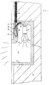
- the component 2 shown in the figures consists of two (not shown) Mold halves that are assembled into a component. Doing so the mold halves mirror each other.
- the component has one in both Molded halves formed trapezoidal depression 10, which in the upper region is covered by an opaque panel element 12.
- the aperture element 12 is relatively thin and covers approximately the upper half of the depression 10 from.
- the panel element 12 runs approximately parallel to a rear wall 15 of the Component.
- the depression 10 is delimited in the lower area by an inner wall 14 or 14 ', in their upper area to the rear wall 15 and in its front area borders on an outer surface of the component. Further is the depression 10 is delimited by one opposite the inner wall 14 or 14 ' Inner wall 16 to which a light source holder 4 is attached.
- Fig. 1 From the front an observer looks through the uncovered area of the depression 10 on the inclined or straight inner wall 14 or 14 '.
- Fig. 1 is the inner wall 14 perpendicular to the rear wall 15.
- the inner wall 14 ' is chamfered.
- the panel element 12 covers the light source holder 4 arranged behind it and, if necessary, the therein used light source 6.
- a passage 30 is formed, which the interior of the Recess 10 connects to the outer surface of the component.
- the passage 30 serves as a connection cavity for connection of an input power cable with a connection cable of the light source holder.
- the passage 30 is circular cylindrical; Starting from the passage 30 upwards is a thin cable duct 32 provided, which extends from the passage 30 up through the inner wall 16 extends.
- the cable duct 32 serves to receive an empty pipe 34, in which the input power cable is routed through.
- the light source holder 4 is fastened integrated on the inner wall 16, specifically with a tube elbow 36.
- One inserted in the light source holder Incandescent lamp serves as light source 6 and generates indirect indirect lighting in the room adjacent to the component by reflection on the oblique or straight inner wall 14 or 14 '.
- a protective glass for the light source 6 connected to this in front of the outside Protect action or against a user reaching into the recess Secure combustion.
- the passage 30 is fixed at its front end face or opening by a mounted cover element 38 closed, which serves as an optical veneer and covers the passage aesthetically.
- On its inner or inner The face or opening is the passage through an inner cover element 40 closed, but which is removable to the in the Passage 30 formed connection cavity for revision or repair purposes to make it accessible.
- the input power cable is through the empty tube 34, the cable duct 32 and through the passage 30 with the pipe elbow 36 of the light source holder 4 connected. That with clamp arms 42 provided cover element 40 can be removed to the rear, as shown in FIG. 2, and as a result, the input power cable guided in the passage 30 can be remove and repair, for example.
- the component is in a recess in a wall 8 or masonry installed, whereby it should be flush with the outer edges.
- the panel element 12 is preferably with a on its front outer surface Recess 28 formed, the depth of about 1 to 2 cm, particularly preferred about 1.5 cm.
- the purpose of the recess is to cover the entire panel element to be able to plaster step-free including the cover element 38.
Landscapes
- Engineering & Computer Science (AREA)
- General Engineering & Computer Science (AREA)
- Arrangement Of Elements, Cooling, Sealing, Or The Like Of Lighting Devices (AREA)
- Hooks, Suction Cups, And Attachment By Adhesive Means (AREA)
Applications Claiming Priority (2)
| Application Number | Priority Date | Filing Date | Title |
|---|---|---|---|
| DE1997135013 DE19735013C1 (de) | 1997-08-12 | 1997-08-12 | Bauelement mit Deckelelement |
| DE19735013 | 1997-08-12 |
Publications (2)
| Publication Number | Publication Date |
|---|---|
| EP0897084A2 true EP0897084A2 (fr) | 1999-02-17 |
| EP0897084A3 EP0897084A3 (fr) | 2001-01-24 |
Family
ID=7838815
Family Applications (1)
| Application Number | Title | Priority Date | Filing Date |
|---|---|---|---|
| EP98114666A Withdrawn EP0897084A3 (fr) | 1997-08-12 | 1998-08-04 | Elément de construction avec support de lampe |
Country Status (2)
| Country | Link |
|---|---|
| EP (1) | EP0897084A3 (fr) |
| DE (1) | DE19735013C1 (fr) |
Families Citing this family (5)
| Publication number | Priority date | Publication date | Assignee | Title |
|---|---|---|---|---|
| DE19830445A1 (de) * | 1998-07-08 | 2000-01-13 | Martin Gruetzner | Einputzrahmen für Einbauleuchten |
| DE19949833C2 (de) * | 1999-10-15 | 2001-08-02 | Gabriele Rechl | Bauelement mit Aufnahme |
| DE20308470U1 (de) | 2003-05-30 | 2003-09-04 | Stippel, Thomas, 83367 Petting | Unterputz-Röhrenleuchte |
| ITTV20120242A1 (it) * | 2012-12-21 | 2014-06-22 | Mas Gianluigi Dal | Dispositivo di illuminazione da incasso e relativo metodo di produzione |
| US11953176B2 (en) * | 2021-11-26 | 2024-04-09 | Brilliant Factors Inc. | Recessed concrete luminaire and method of installation thereof |
Citations (1)
| Publication number | Priority date | Publication date | Assignee | Title |
|---|---|---|---|---|
| DE4331199C1 (de) | 1993-09-14 | 1995-03-30 | Rudolf Rechl | Bauelement mit Lichtquellenhalter |
Family Cites Families (3)
| Publication number | Priority date | Publication date | Assignee | Title |
|---|---|---|---|---|
| DE2355722A1 (de) * | 1973-11-08 | 1975-05-28 | Grohe Armaturen Friedrich | Leuchte |
| GB9404962D0 (en) * | 1994-03-15 | 1994-04-27 | Marsh Neville R | Light brick |
| US5683170A (en) * | 1996-02-12 | 1997-11-04 | Blaha; Michael J. | Iluminated masonary block or brick |
-
1997
- 1997-08-12 DE DE1997135013 patent/DE19735013C1/de not_active Expired - Fee Related
-
1998
- 1998-08-04 EP EP98114666A patent/EP0897084A3/fr not_active Withdrawn
Patent Citations (1)
| Publication number | Priority date | Publication date | Assignee | Title |
|---|---|---|---|---|
| DE4331199C1 (de) | 1993-09-14 | 1995-03-30 | Rudolf Rechl | Bauelement mit Lichtquellenhalter |
Also Published As
| Publication number | Publication date |
|---|---|
| EP0897084A3 (fr) | 2001-01-24 |
| DE19735013C1 (de) | 1998-11-05 |
Similar Documents
| Publication | Publication Date | Title |
|---|---|---|
| DE602005001398T2 (de) | Einrichtung zur unterstützung einer bündigen wandanbringung für elektrische oder elektronische komponenten | |
| EP0446875A2 (fr) | Boîtiers de protection pour dispositifs optiques | |
| DE19735013C1 (de) | Bauelement mit Deckelelement | |
| DE202007013698U1 (de) | Wandkanalinstallation mit einem im Mauerstein eingesetzten Kabelkanal für Gebäudeinnenräume | |
| CH687564A5 (de) | Halogenlampe zum Eingiessen in eine Betondecke und Betondecke mit wenigstens einer derartigen Halogenlampe. | |
| DE4331199C1 (de) | Bauelement mit Lichtquellenhalter | |
| EP0228425A1 (fr) | Dispositif d'eclairage pour machines a ecrire ou imprimantes. | |
| DE102004051661B3 (de) | Leuchte und Lichtquelleneinheit zur Ausleuchtung einer Gebäudefläche oder einer Gebäudeteilfläche | |
| EP0582945A2 (fr) | Elément de mur multifonctionnel pour équipements de bureau et d'autres équipements de poste de travail | |
| DE19949833C2 (de) | Bauelement mit Aufnahme | |
| DE29516860U1 (de) | Beleuchtungssystem, Leuchtkörper für ein solches System sowie Lichtquelle | |
| DE202021101189U1 (de) | Formprofil | |
| DE10113611B4 (de) | Vorrichtung zur Aufnahme von Leitungen | |
| EP0739069B1 (fr) | Dispositif de raccordement combiné | |
| DE602005001049T2 (de) | Kabelinstallations-hilfseinrichtung | |
| DE19908065C2 (de) | Lüftungsaggregat | |
| DE29711053U1 (de) | Vorrichtung zur Dachentwässerung, insbesondere Dachrinne mit Fallrohr und/oder Rinneneisen | |
| DE102019133788A1 (de) | Vorrichtung zum Durchführen wenigstens eines Glasfaser-Kabels durch eine Wandbohrung | |
| DE19917913A1 (de) | Bodenkanal | |
| DE2819628C3 (de) | Hängeschrank für Einbauküchen | |
| DE102018119768A1 (de) | Sockelleistenhalter und Sockenleistensystem | |
| DE29520862U1 (de) | Kamera zur Innenuntersuchung von Rohren | |
| DE19519416C1 (de) | Anschlußübergangseinrichtung | |
| DE1971417U (de) | Farbzeichengeber, insbesondere strassenampel. | |
| DE3738058A1 (de) | Verbindungskanal zwischen einer kabelbahn und einem schrank, bausatz und verfahren zur herstellung des verbindungskanals |
Legal Events
| Date | Code | Title | Description |
|---|---|---|---|
| PUAI | Public reference made under article 153(3) epc to a published international application that has entered the european phase |
Free format text: ORIGINAL CODE: 0009012 |
|
| AK | Designated contracting states |
Kind code of ref document: A2 Designated state(s): AT CH ES FR IT LI |
|
| AX | Request for extension of the european patent |
Free format text: AL;LT;LV;MK;RO;SI |
|
| PUAL | Search report despatched |
Free format text: ORIGINAL CODE: 0009013 |
|
| AK | Designated contracting states |
Kind code of ref document: A3 Designated state(s): AT BE CH CY DE DK ES FI FR GB GR IE IT LI LU MC NL PT SE |
|
| AX | Request for extension of the european patent |
Free format text: AL;LT;LV;MK;RO;SI |
|
| 17P | Request for examination filed |
Effective date: 20001220 |
|
| AKX | Designation fees paid | ||
| REG | Reference to a national code |
Ref country code: DE Ref legal event code: 8566 |
|
| RBV | Designated contracting states (corrected) |
Designated state(s): AT CH ES FR IT LI |
|
| RBV | Designated contracting states (corrected) |
Designated state(s): AT CH ES FR IT LI |
|
| APAX | Date of receipt of notice of appeal deleted |
Free format text: ORIGINAL CODE: EPIDOSDNOA2E |
|
| APBN | Date of receipt of notice of appeal recorded |
Free format text: ORIGINAL CODE: EPIDOSNNOA2E |
|
| STAA | Information on the status of an ep patent application or granted ep patent |
Free format text: STATUS: THE APPLICATION IS DEEMED TO BE WITHDRAWN |
|
| 18D | Application deemed to be withdrawn |
Effective date: 20030301 |