EP0897084A2 - Building component with light-holder - Google Patents
Building component with light-holder Download PDFInfo
- Publication number
- EP0897084A2 EP0897084A2 EP98114666A EP98114666A EP0897084A2 EP 0897084 A2 EP0897084 A2 EP 0897084A2 EP 98114666 A EP98114666 A EP 98114666A EP 98114666 A EP98114666 A EP 98114666A EP 0897084 A2 EP0897084 A2 EP 0897084A2
- Authority
- EP
- European Patent Office
- Prior art keywords
- light source
- component
- wall
- recess
- source holder
- Prior art date
- Legal status (The legal status is an assumption and is not a legal conclusion. Google has not performed a legal analysis and makes no representation as to the accuracy of the status listed.)
- Withdrawn
Links
- 238000009434 installation Methods 0.000 claims abstract description 3
- 238000005286 illumination Methods 0.000 abstract 1
- 238000007689 inspection Methods 0.000 description 3
- 238000002485 combustion reaction Methods 0.000 description 1
- 239000011521 glass Substances 0.000 description 1
- 230000003287 optical effect Effects 0.000 description 1
- 239000011505 plaster Substances 0.000 description 1
- 230000001681 protective effect Effects 0.000 description 1
Images

Classifications
-
- F—MECHANICAL ENGINEERING; LIGHTING; HEATING; WEAPONS; BLASTING
- F21—LIGHTING
- F21S—NON-PORTABLE LIGHTING DEVICES; SYSTEMS THEREOF; VEHICLE LIGHTING DEVICES SPECIALLY ADAPTED FOR VEHICLE EXTERIORS
- F21S8/00—Lighting devices intended for fixed installation
- F21S8/02—Lighting devices intended for fixed installation of recess-mounted type, e.g. downlighters
Definitions
- the present invention relates to a component according to the preamble of Such a component is for example from DE 43 31 199 C1 known.
- This generic component has a light source holder and is for installation in a wall or for building a wall or a Support element determined in buildings.
- the one with a light source Light source holder ensures comfortable indirect lighting of the on the Component adjacent interior.
- the known component has the disadvantage that the cables for power supply routed inside the light source are only accessible from the outside, by an in recess formed on the surface of the panel element. However, this prevents an optically satisfactory concealment of the component and a revision from the inside.
- the object of the present invention is the further development of the generic Component in such a way that access to inner lines also is perfectly feasible from the inside for inspection or repair purposes.
- the diaphragm element has a passage at its rear opening is closed by a removable cover element.
- a removable cover element Of the preferably circular cylindrical passage enables the introduction of cabling either through the front or inner rear opening of the passage.
- the outer cover element After closing the openings by removable cover elements can the outer cover element are plastered optically satisfactory, while the Inner cover element can be removed for inspection or repair of the wiring is.
- a cable duct preferably opens into the passage. This makes the electrical Power supply possible.
- An empty pipe or a cable is preferably inserted in the cable duct.
- the Empty pipe or the cable are used to guide the electrical lines.
- An outer cover element preferably closes the front opening of the Continuity. This is a perfect outer veneer of the cover element and thus the entire component.
- the cover elements are preferably provided with clamp arms.
- the bracket arms have spreading function so that the lid can be conveniently put on manually and can be dismantled.
- the outer cover is particularly preferably fixed mounted while the inner cover is removed for inspection purposes can.
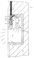
- the component 2 shown in the figures consists of two (not shown) Mold halves that are assembled into a component. Doing so the mold halves mirror each other.
- the component has one in both Molded halves formed trapezoidal depression 10, which in the upper region is covered by an opaque panel element 12.
- the aperture element 12 is relatively thin and covers approximately the upper half of the depression 10 from.
- the panel element 12 runs approximately parallel to a rear wall 15 of the Component.
- the depression 10 is delimited in the lower area by an inner wall 14 or 14 ', in their upper area to the rear wall 15 and in its front area borders on an outer surface of the component. Further is the depression 10 is delimited by one opposite the inner wall 14 or 14 ' Inner wall 16 to which a light source holder 4 is attached.
- Fig. 1 From the front an observer looks through the uncovered area of the depression 10 on the inclined or straight inner wall 14 or 14 '.
- Fig. 1 is the inner wall 14 perpendicular to the rear wall 15.
- the inner wall 14 ' is chamfered.
- the panel element 12 covers the light source holder 4 arranged behind it and, if necessary, the therein used light source 6.
- a passage 30 is formed, which the interior of the Recess 10 connects to the outer surface of the component.
- the passage 30 serves as a connection cavity for connection of an input power cable with a connection cable of the light source holder.
- the passage 30 is circular cylindrical; Starting from the passage 30 upwards is a thin cable duct 32 provided, which extends from the passage 30 up through the inner wall 16 extends.
- the cable duct 32 serves to receive an empty pipe 34, in which the input power cable is routed through.
- the light source holder 4 is fastened integrated on the inner wall 16, specifically with a tube elbow 36.
- One inserted in the light source holder Incandescent lamp serves as light source 6 and generates indirect indirect lighting in the room adjacent to the component by reflection on the oblique or straight inner wall 14 or 14 '.
- a protective glass for the light source 6 connected to this in front of the outside Protect action or against a user reaching into the recess Secure combustion.
- the passage 30 is fixed at its front end face or opening by a mounted cover element 38 closed, which serves as an optical veneer and covers the passage aesthetically.
- On its inner or inner The face or opening is the passage through an inner cover element 40 closed, but which is removable to the in the Passage 30 formed connection cavity for revision or repair purposes to make it accessible.
- the input power cable is through the empty tube 34, the cable duct 32 and through the passage 30 with the pipe elbow 36 of the light source holder 4 connected. That with clamp arms 42 provided cover element 40 can be removed to the rear, as shown in FIG. 2, and as a result, the input power cable guided in the passage 30 can be remove and repair, for example.
- the component is in a recess in a wall 8 or masonry installed, whereby it should be flush with the outer edges.
- the panel element 12 is preferably with a on its front outer surface Recess 28 formed, the depth of about 1 to 2 cm, particularly preferred about 1.5 cm.
- the purpose of the recess is to cover the entire panel element to be able to plaster step-free including the cover element 38.
Landscapes
- Engineering & Computer Science (AREA)
- General Engineering & Computer Science (AREA)
- Arrangement Of Elements, Cooling, Sealing, Or The Like Of Lighting Devices (AREA)
- Hooks, Suction Cups, And Attachment By Adhesive Means (AREA)
Abstract
Description
Die vorliegende Erfindung betrifft ein Bauelement gemäß dem Oberbegriff des Anspruchs 1. Ein derartiges Bauelement ist beispielsweise aus der DE 43 31 199 C1 bekannt. Dieses gattungsgemäße Bauelement weist einen Lichtquellenhalter auf und ist zum Einbau in eine Wand oder zum Aufbau einer Wand oder eines Stützelementes in Gebäuden bestimmt. Der mit einer Lichtquelle versehene Lichtquellenhalter sorgt für eine komfortable indirekte Beleuchtung des an das Bauelement angrenzenden Innenraums. Das bekannte Bauelement hat jedoch den Nachteil, daß die in seinem Inneren geführten Leitungen für die Stromversorgung der Lichtquelle nur von außen zugänglich sind, und zwar durch eine in der Oberfläche des Blendenelementes gebildete Aussparung. Dies verhindert jedoch eine optisch befriedigende Verdeckung des Bauelementes und eine Revision von innen.The present invention relates to a component according to the preamble of Such a component is for example from DE 43 31 199 C1 known. This generic component has a light source holder and is for installation in a wall or for building a wall or a Support element determined in buildings. The one with a light source Light source holder ensures comfortable indirect lighting of the on the Component adjacent interior. However, the known component has the disadvantage that the cables for power supply routed inside the light source are only accessible from the outside, by an in recess formed on the surface of the panel element. However, this prevents an optically satisfactory concealment of the component and a revision from the inside.
Aufgabe der vorliegenden Erfindung ist die Weiterentwicklung des gattungsgemäßen Bauelementes in der Weise, daß ein Zugriff auf innere Leitungen auch von innen zu Revisions- oder Reparaturzwecken einwandfrei möglich ist.The object of the present invention is the further development of the generic Component in such a way that access to inner lines also is perfectly feasible from the inside for inspection or repair purposes.
Diese Aufgabe wird erfindungsgemäß bei einem gattungsgemäßen Bauelement dadurch gelöst, daß das Blendenelement einen Durchgang aufweist, der an seiner hinteren Öffnung durch ein abnehmbares Deckelelement verschlossen ist. Der bevorzugt kreiszylindrische Durchgang ermöglicht die Einbringung von Verkabelung entweder durch die vordere oder die innere hintere Öffnung des Durchgangs. Nach Verschluß der Öffnungen durch abnehmbare Deckelelemente kann das äußere Deckelelement optisch befriedigend verputzt werden, während das innere Deckelelement zur Revision bzw. Reparatur der Verkabelung demontierbar ist.This object is achieved according to the invention in a generic component solved in that the diaphragm element has a passage at its rear opening is closed by a removable cover element. Of the preferably circular cylindrical passage enables the introduction of cabling either through the front or inner rear opening of the passage. After closing the openings by removable cover elements can the outer cover element are plastered optically satisfactory, while the Inner cover element can be removed for inspection or repair of the wiring is.
Bevorzugt mündet in dem Durchgang ein Kabelkanal. Dadurch ist die elektrische Stromversorgung möglich.A cable duct preferably opens into the passage. This makes the electrical Power supply possible.
In dem Kabelkanal ist bevorzugt ein Leerrohr oder ein Kabel eingeführt. Das Leerrohr oder das Kabel dienen zur Führung der elektrischen Leitungen.An empty pipe or a cable is preferably inserted in the cable duct. The Empty pipe or the cable are used to guide the electrical lines.
Ein äußeres Deckelelement verschließt bevorzugt die vordere Öffnung des Durchgangs. Dadurch ist eine einwandfreie äußere Verblendung des Deckelelementes und damit des gesamten Bauelementes sichergestellt.An outer cover element preferably closes the front opening of the Continuity. This is a perfect outer veneer of the cover element and thus the entire component.
Die Deckelemente sind bevorzugt mit Klammerarmen versehen. Die Klammerarme haben Spreizfunktion, so daß der Deckel bequem manuell aufgesetzt und demontiert werden kann. Besonders bevorzugt ist der äußere Deckel fest montiert, während der innere Deckel zu Revisionszwecken abgenommen werden kann.The cover elements are preferably provided with clamp arms. The bracket arms have spreading function so that the lid can be conveniently put on manually and can be dismantled. The outer cover is particularly preferably fixed mounted while the inner cover is removed for inspection purposes can.
Bevorzugte Ausführungsbeispiele, die von der Erfindung Gebrauch machen,
werden nachfolgend in Verbindung mit der Zeichnung beschrieben.
Das in den Figuren dargestellte Bauelement 2 besteht aus zwei (nicht gezeigten)
Formhälften, die zu einem Bauelement zusammengesetzt werden. Dabei entsprechen
die Formhälften einander spiegelbildlich. Das Bauelement weist eine in beiden
Formhälften gebildete trapezförmige Vertiefung 10 auf, die im oberen Bereich
von einem lichtundurchlässigen Blendenelement 12 verdeckt ist. Das Blendenelement
12 ist relativ dünn und deckt etwa die obere Hälfte der Vertiefung 10
ab. Das Blendenelement 12 verläuft etwa parallel zu einer hinteren Wand 15 des
Bauelementes. Die Vertiefung 10 ist im unteren Bereich begrenzt von einer Innenwand
14 bzw. 14', die in ihrem oberen Bereich an die hintere Wand 15 und in
ihrem vorderen Bereich an eine Außenfläche des Bauelementes grenzt. Ferner ist
die Vertiefung 10 begrenzt von einer der Innenwand 14 bzw. 14' gegenüberliegenden
Innenwand 16, an der ein Lichtquellenhalter 4 befestigt ist. Von vorne
schaut ein Beobachter durch den unverdeckten Bereich der Vertiefung 10 hindurch
auf die schräge oder gerade Innenwand 14 bzw. 14'. In der Ausführung von
Fig. 1 ist die Innenwand 14 senkrecht zur hinteren Wand 15. In der Ausführung
von Fig. 2 ist die Innenwand 14' abgeschrägt. Das Blendenelement 12 überdeckt
den hinter ihr angeordneten Lichtquellenhalter 4 und die darin gegebenenfalls
eingesetzte Lichtquelle 6.The
In dem Blendenelement 12 ist ein Durchgang 30 gebildet, der den Innenraum der
Vertiefung 10 mit der Außenfläche des Bauelementes verbindet. Der Durchgang
30 dient als Anschlußhohlraum für eine Verbindung eines Eingangsstromkabels
mit einem Anschlußkabel des Lichtquellenhalters. Der Durchgang 30 ist kreiszylindrisch;
von dem Durchgang 30 ausgehend nach oben ist ein dünner Kabelkanal
32 vorgesehen, der sich von dem Durchgang 30 nach oben durch die Innenwand
16 erstreckt. Der Kabelkanal 32 dient zur Aufnahme eines Leerrohrs 34, in
dem das Eingangsstromkabel geführt ist.In the
An der Innenwand 16 ist der Lichtquellenhalter 4 integriert befestigt, und zwar
mit einem Rohrwinkelstück 36. Eine in dem Lichtquellenhalter eingesetzte
Glühlampe dient als Lichtquelle 6 und erzeugt eine mittelbare indirekte Beleuchtung
im an das Bauelement angrenzenden Raum durch Reflexion an der schrägen
oder geraden Innenwand 14 bzw. 14'. Mit dem Lichtquellenhalter 4 ist im
Bedarfsfall ein Schutzglas für die Lichtquelle 6 verbunden, um diese vor äußerer
Einwirkung zu schützen bzw. einen in die Vertiefung greifenden Benutzer gegen
Verbrennung zu sichern.The light source holder 4 is fastened integrated on the
Der Durchgang 30 ist an seiner vorderen Stirnfläche bzw. Öffnung durch ein fest
montiertes Deckelelement 38 verschlossen, das als optische Verblendung dient
und den Durchgang ästhetisch befriedigend abdeckt. An seiner inneren bzw. innenliegenden
Stirnfläche bzw. Öffnung ist der Durchgang durch ein inneres Deckelelement
40 verschlossen, welches jedoch abnehmbar ist, um den in dem
Durchgang 30 gebildeten Anschlußhohlraum für Revisionszwecke bzw. Reparaturzwecke
zugänglich zu machen. Das Eingangsstromkabel ist durch das Leerohr
34, den Kabelkanal 32 und durch den Durchgang 30 geführt mit dem Rohrwinkelstück
36 des Lichtquellenhalters 4 verbunden. Das mit Klammerarmen 42
versehene Deckelelement 40 läßt sich, wie in Figur 2 gezeigt, nach hinten abnehmen,
und in der Folge läßt sich das in dem Durchgang 30 geführte Eingangsstromkabel
herausnehmen und beispielsweise reparieren.The
Das Bauelement wird in einer Ausnehmung einer Wand 8 oder eines Mauerwerks
eingebaut, wobei es mit dessen Außenkanten bündig abschließen soll.The component is in a recess in a
Das Blendenelement 12 ist an seiner vorderen Außenfläche bevorzugt mit einer
Vertiefung 28 ausgebildet, die eine Tiefe von etwa 1 bis 2 cm, besonders bevorzugt
etwa 1,5 cm hat. Die Vertiefung hat den Zweck, das gesamte Blendenelement
einschließlich des Deckelelementes 38 stufenfrei verputzen zu können.The
Claims (5)
Applications Claiming Priority (2)
| Application Number | Priority Date | Filing Date | Title |
|---|---|---|---|
| DE19735013 | 1997-08-12 | ||
| DE1997135013 DE19735013C1 (en) | 1997-08-12 | 1997-08-12 | Building component with cover element for light fitting in wall |
Publications (2)
| Publication Number | Publication Date |
|---|---|
| EP0897084A2 true EP0897084A2 (en) | 1999-02-17 |
| EP0897084A3 EP0897084A3 (en) | 2001-01-24 |
Family
ID=7838815
Family Applications (1)
| Application Number | Title | Priority Date | Filing Date |
|---|---|---|---|
| EP98114666A Withdrawn EP0897084A3 (en) | 1997-08-12 | 1998-08-04 | Building component with light-holder |
Country Status (2)
| Country | Link |
|---|---|
| EP (1) | EP0897084A3 (en) |
| DE (1) | DE19735013C1 (en) |
Families Citing this family (5)
| Publication number | Priority date | Publication date | Assignee | Title |
|---|---|---|---|---|
| DE19830445A1 (en) * | 1998-07-08 | 2000-01-13 | Martin Gruetzner | In-plaster mounted frame for installed lighting |
| DE19949833C2 (en) * | 1999-10-15 | 2001-08-02 | Gabriele Rechl | Component with holder |
| DE20308470U1 (en) | 2003-05-30 | 2003-09-04 | Stippel, Thomas, 83367 Petting | Concealed tube light |
| ITTV20120242A1 (en) * | 2012-12-21 | 2014-06-22 | Mas Gianluigi Dal | BUILT-IN LIGHTING DEVICE AND ITS PRODUCTION METHOD |
| US11953176B2 (en) * | 2021-11-26 | 2024-04-09 | Brilliant Factors Inc. | Recessed concrete luminaire and method of installation thereof |
Citations (1)
| Publication number | Priority date | Publication date | Assignee | Title |
|---|---|---|---|---|
| DE4331199C1 (en) | 1993-09-14 | 1995-03-30 | Rudolf Rechl | Component with light source holder |
Family Cites Families (3)
| Publication number | Priority date | Publication date | Assignee | Title |
|---|---|---|---|---|
| DE2355722A1 (en) * | 1973-11-08 | 1975-05-28 | Grohe Armaturen Friedrich | Bathroom or kitchen wall lamp - is dimensioned to match tiling and has connectors to form patterned arrays |
| GB9404962D0 (en) * | 1994-03-15 | 1994-04-27 | Marsh Neville R | Light brick |
| US5683170A (en) * | 1996-02-12 | 1997-11-04 | Blaha; Michael J. | Iluminated masonary block or brick |
-
1997
- 1997-08-12 DE DE1997135013 patent/DE19735013C1/en not_active Expired - Fee Related
-
1998
- 1998-08-04 EP EP98114666A patent/EP0897084A3/en not_active Withdrawn
Patent Citations (1)
| Publication number | Priority date | Publication date | Assignee | Title |
|---|---|---|---|---|
| DE4331199C1 (en) | 1993-09-14 | 1995-03-30 | Rudolf Rechl | Component with light source holder |
Also Published As
| Publication number | Publication date |
|---|---|
| DE19735013C1 (en) | 1998-11-05 |
| EP0897084A3 (en) | 2001-01-24 |
Similar Documents
| Publication | Publication Date | Title |
|---|---|---|
| EP0446875A2 (en) | Protective casings for optical devices | |
| DE19623708C1 (en) | Ventilation apparatus for living rooms and offices | |
| DE19735013C1 (en) | Building component with cover element for light fitting in wall | |
| DE202007013698U1 (en) | Wall duct installation with a cable duct used in the brick for building interiors | |
| DE4331199C1 (en) | Component with light source holder | |
| DE29500660U1 (en) | Halogen lamp for pouring into a concrete ceiling and concrete ceiling with at least one such halogen lamp | |
| EP0228425A1 (en) | Lighting device for typewriters or printers. | |
| DE29609158U1 (en) | Housing for accommodating installation components | |
| DE102004051661B3 (en) | Illumination system for whole or part of building wall has tube with lights of different colors in triangular array, with reflector portion and transparent portion admitting light to curved mirror | |
| DE19949833C2 (en) | Component with holder | |
| DE29516860U1 (en) | Lighting system, illuminant for such a system and light source | |
| DE202021101189U1 (en) | Shape profile | |
| DE10113611B4 (en) | Device for receiving lines | |
| DE19908065C2 (en) | Ventilation unit | |
| DE29711053U1 (en) | Device for roof drainage, in particular gutter with downpipe and / or gutter iron | |
| DE102019133788A1 (en) | Device for guiding at least one fiber optic cable through a hole in the wall | |
| DE19917913A1 (en) | Floor electrical installation channel has trough and cooperating removable cover provided with projection extending over intersection with trough wall | |
| DE2819628C3 (en) | Wall cabinet for fitted kitchens | |
| DE102018119768A1 (en) | Skirting board holder and skirting board system | |
| DE29520862U1 (en) | Internal pipe inspection camera | |
| DE19519416C1 (en) | Pipe joint or union used in heating system | |
| DE19514883A1 (en) | Combined connection device | |
| DE3738058A1 (en) | Connecting channel between a cable run and a cabinet, and a kit and method for producing the connecting channel | |
| EP0458191A2 (en) | Edge lining for thin window sills or the like | |
| DE9310439U1 (en) | Cable duct system for electrical lines |
Legal Events
| Date | Code | Title | Description |
|---|---|---|---|
| PUAI | Public reference made under article 153(3) epc to a published international application that has entered the european phase |
Free format text: ORIGINAL CODE: 0009012 |
|
| AK | Designated contracting states |
Kind code of ref document: A2 Designated state(s): AT CH ES FR IT LI |
|
| AX | Request for extension of the european patent |
Free format text: AL;LT;LV;MK;RO;SI |
|
| PUAL | Search report despatched |
Free format text: ORIGINAL CODE: 0009013 |
|
| AK | Designated contracting states |
Kind code of ref document: A3 Designated state(s): AT BE CH CY DE DK ES FI FR GB GR IE IT LI LU MC NL PT SE |
|
| AX | Request for extension of the european patent |
Free format text: AL;LT;LV;MK;RO;SI |
|
| 17P | Request for examination filed |
Effective date: 20001220 |
|
| AKX | Designation fees paid | ||
| REG | Reference to a national code |
Ref country code: DE Ref legal event code: 8566 |
|
| RBV | Designated contracting states (corrected) |
Designated state(s): AT CH ES FR IT LI |
|
| RBV | Designated contracting states (corrected) |
Designated state(s): AT CH ES FR IT LI |
|
| APAX | Date of receipt of notice of appeal deleted |
Free format text: ORIGINAL CODE: EPIDOSDNOA2E |
|
| APBN | Date of receipt of notice of appeal recorded |
Free format text: ORIGINAL CODE: EPIDOSNNOA2E |
|
| STAA | Information on the status of an ep patent application or granted ep patent |
Free format text: STATUS: THE APPLICATION IS DEEMED TO BE WITHDRAWN |
|
| 18D | Application deemed to be withdrawn |
Effective date: 20030301 |