EP0896130B1 - Al or Al alloy poppet valve and a method of manufacturing the same - Google Patents
Al or Al alloy poppet valve and a method of manufacturing the same Download PDFInfo
- Publication number
- EP0896130B1 EP0896130B1 EP98114647A EP98114647A EP0896130B1 EP 0896130 B1 EP0896130 B1 EP 0896130B1 EP 98114647 A EP98114647 A EP 98114647A EP 98114647 A EP98114647 A EP 98114647A EP 0896130 B1 EP0896130 B1 EP 0896130B1
- Authority
- EP
- European Patent Office
- Prior art keywords
- valve
- alloy
- face
- reinforcement material
- layer
- Prior art date
- Legal status (The legal status is an assumption and is not a legal conclusion. Google has not performed a legal analysis and makes no representation as to the accuracy of the status listed.)
- Expired - Lifetime
Links
Images


Classifications
-
- F—MECHANICAL ENGINEERING; LIGHTING; HEATING; WEAPONS; BLASTING
- F01—MACHINES OR ENGINES IN GENERAL; ENGINE PLANTS IN GENERAL; STEAM ENGINES
- F01L—CYCLICALLY OPERATING VALVES FOR MACHINES OR ENGINES
- F01L3/00—Lift-valve, i.e. cut-off apparatus with closure members having at least a component of their opening and closing motion perpendicular to the closing faces; Parts or accessories thereof
- F01L3/02—Selecting particular materials for valve-members or valve-seats; Valve-members or valve-seats composed of two or more materials
- F01L3/04—Coated valve members or valve-seats
-
- Y—GENERAL TAGGING OF NEW TECHNOLOGICAL DEVELOPMENTS; GENERAL TAGGING OF CROSS-SECTIONAL TECHNOLOGIES SPANNING OVER SEVERAL SECTIONS OF THE IPC; TECHNICAL SUBJECTS COVERED BY FORMER USPC CROSS-REFERENCE ART COLLECTIONS [XRACs] AND DIGESTS
- Y10—TECHNICAL SUBJECTS COVERED BY FORMER USPC
- Y10T—TECHNICAL SUBJECTS COVERED BY FORMER US CLASSIFICATION
- Y10T29/00—Metal working
- Y10T29/49—Method of mechanical manufacture
- Y10T29/49405—Valve or choke making
Definitions
- the present invention relates to an Al or Al alloy poppet valve in an internal combustion engine, and a method of manufacturing the same.
- Inlet and exhaust poppet valves in an internal combustion engine for a vehicle are generally made of heat-resistant steel such as martensite and austenite. Recently an inlet valve which has relatively low thermal load is made of Al alloy; see for example JP 59128908.
- the heat resistant steel valve has high mechanical strength, and provides high durability and reliability, but has high inertia mass and low heat conductivity.
- the Al alloy inlet valve which is light decreases inertia mass of a valve-operating mechanism, and increase engine performance, thereby providing high heat conductivity and high heat release performance to the cylinder head to increase cooling performance of the engine.
- Al alloy has low mechanical strength and especially low wear resistance on the valve face to provide low durability and reliability.
- an object of the present invention to provide an Al alloy poppet valve in an internal combustion engine which provides increase in strength, especially in mechanical strength of a valve face, and a method of manufacturing it.
- an Al or Al alloy poppet valve in an internal combustion engine, said valve comprising a valve stem and a valve head at an end of the valve stem, said valve head having a valve face which is engageable on a valve seat, said valve face having a thermal hardened layer at a surface, and an inner alloy layer which contains reinforcement material.
- the poppet valve increases durability to impact and mechanical strength.
- Hardeness and strength of the valve face of the A1 or Al alloy poppet valve are increased, thereby decreasing inertia mass of a valve operating mechanism to increase engine performance.
- Fig. 1 illustrates a section of a valve face of a valve head of an inlet valve 10 in an internal combustion engine.
- the inlet valve 10 is made of Al alloy such as Al-Si and Al-Si-Cu.
- the valve head 10b is provided at the lower end of a valve stem 10a.
- the surface layer 12a is formed as thermal hardened layer, and an inner layer 12b is made of a reinforcement material such as Ti, Cr, Ni, Cu, Mn, Fe and Co, or an alloy layer of two or more reinforcement elements thereof.
- the alloy layer has hardness of 250 to 300Hv which is much higher than hardness of Al matrix of 120 to 150Hv.
- the alloy layer formed at the lower portion includes intermetallic compounds of Al matrix and reinforcement material, thereby increasing mechanical strength of the inner layer 12b.
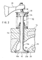
- FIG. 2 illustrates the inlet valve 10 mounted to a cylinder head 14.
- the valve stem 10a of the inlet valve 10 is slidably inserted in a valve guide 16 of the cylinder head 14.
- the valve face 12 of the inlet valve 10 is engaged on a seat portion 20a of a valve seat 20 at the lower end of an inlet port 18 when an inlet port is closed by the inlet valve, Large impacting force is applied onto the valve face 12 by engagement with the valve seat 20.
- the surface layer 12a comprises a hardened layer
- the inner layer 12b comprises an alloy layer, thereby increasing durability to impact significantly.
- a spring retainer 22 is mounted via a pair of cotters(not shown). Between the spring retainer 22 and the upper surface of the cylinder head 14, a valve spring 24 is provided to bias the inlet valve 10 upwards.
- a rocker arm 26 which moves up and down by a cam (not shown) is provided, and the upper end of the inlet valve 10 is pressed by the lower end of an adjuter bolt 28 which is engaged at the end of the rocker arm 26, thereby opening the valve.
- Figs. 3 and 4 illustrate the valve face in each step for forming a thermal hardened layer and an alloy layer on the inlet valve 10 as shown in Fig. 1.
- valve face 12 On the surface of the valve face 12, powdery materials of reinforcement elements such as Ti, Cr, Ni, Cu, Mn, Fe and Co are applied and heated by high energy heating means such as YAG laser, CO 2 laser and electronic beam.
- high energy heating means such as YAG laser, CO 2 laser and electronic beam.
- a YAG laser is preferable as high energy heating means, but CO 2 laser has low efficiency because of high reflection rate of the Al matrix.
- the surface of the valve face 10 is corroded by acidic or alkaline substance to form uneven surface, thereby accerating absorption of heat energy.
- T6 treatment under JIS (Japanese Industrial Standards) is applied to the valve face 10, thereby recovering hardness of the inner layer 11b.
- JIS Japanese Industrial Standards
- T6 treatment means heating which comprises the steps of rapid cooling by water quenching after heating at about 500°C, and then heating for several hours at 100 to 200°C.
- valve face 10 is heated again by the high energy heating means such as YAG laser to melt the surface layer again and to form the thermal hardened layer on the outermost surface layer 11c of the valve face 10.
- the high energy heating means such as YAG laser
- hardness of the outermost surface layer 11c of the valve face 10 is increased to 250 to 300Hv.
- mechanical strength of the valve face 10 is much increased together with the alloy layer 11a, thereby increasing durability and reliability of the inlet valve 10.
Landscapes
- Engineering & Computer Science (AREA)
- Mechanical Engineering (AREA)
- General Engineering & Computer Science (AREA)
- Valve-Gear Or Valve Arrangements (AREA)
- Lift Valve (AREA)
- Other Surface Treatments For Metallic Materials (AREA)
- Heat Treatment Of Articles (AREA)
- Laser Beam Processing (AREA)
Applications Claiming Priority (3)
| Application Number | Priority Date | Filing Date | Title |
|---|---|---|---|
| JP21311097 | 1997-08-07 | ||
| JP9213110A JPH1162525A (ja) | 1997-08-07 | 1997-08-07 | 内燃機関用バルブ及びその製造方法 |
| JP213110/97 | 1997-08-07 |
Publications (3)
| Publication Number | Publication Date |
|---|---|
| EP0896130A2 EP0896130A2 (en) | 1999-02-10 |
| EP0896130A3 EP0896130A3 (en) | 2000-04-12 |
| EP0896130B1 true EP0896130B1 (en) | 2002-12-18 |
Family
ID=16633754
Family Applications (1)
| Application Number | Title | Priority Date | Filing Date |
|---|---|---|---|
| EP98114647A Expired - Lifetime EP0896130B1 (en) | 1997-08-07 | 1998-08-04 | Al or Al alloy poppet valve and a method of manufacturing the same |
Country Status (4)
| Country | Link |
|---|---|
| US (1) | US6073912A (enExample) |
| EP (1) | EP0896130B1 (enExample) |
| JP (1) | JPH1162525A (enExample) |
| DE (1) | DE69810211T2 (enExample) |
Families Citing this family (9)
| Publication number | Priority date | Publication date | Assignee | Title |
|---|---|---|---|---|
| JP2001234313A (ja) * | 2000-02-23 | 2001-08-31 | Fuji Oozx Inc | チタン合金製エンジンバルブの製造方法 |
| JP4871293B2 (ja) * | 2005-11-15 | 2012-02-08 | 日鍛バルブ株式会社 | 冷媒入り中空ポペットバルブおよびその製造方法 |
| DE102013216188A1 (de) * | 2013-08-14 | 2015-03-12 | Mahle International Gmbh | Leichtmetalleinlassventil |
| JP5929889B2 (ja) * | 2013-12-26 | 2016-06-08 | トヨタ自動車株式会社 | 過給機 |
| DE102015213706A1 (de) * | 2015-07-21 | 2017-01-26 | Mahle International Gmbh | Tribologisches System, umfassend einen Ventilsitzring und ein Ventil |
| JP6597663B2 (ja) | 2017-02-08 | 2019-10-30 | トヨタ自動車株式会社 | エンジンバルブ |
| KR102285017B1 (ko) | 2018-03-20 | 2021-08-04 | 니탄 밸브 가부시키가이샤 | 배기용 중공 포핏 밸브 |
| KR102638971B1 (ko) | 2018-11-12 | 2024-02-22 | 가부시키가이샤 니탄 | 엔진의 포핏 밸브의 제조 방법 |
| KR102760621B1 (ko) | 2020-03-30 | 2025-02-03 | 가부시키가이샤 니탄 | 엔진의 포핏 밸브의 제조 방법 |
Family Cites Families (7)
| Publication number | Priority date | Publication date | Assignee | Title |
|---|---|---|---|---|
| US4117302A (en) * | 1974-03-04 | 1978-09-26 | Caterpillar Tractor Co. | Method for fusibly bonding a coating material to a metal article |
| JPS5222623A (en) * | 1975-08-15 | 1977-02-21 | Toyota Motor Corp | Popet valve body and its manufacturing process |
| DE2856232A1 (de) * | 1978-12-27 | 1980-07-17 | Teves Thompson Gmbh | Thermisch und korrosiv hoch beanspruchtes tellerventil |
| US4554898A (en) * | 1980-10-31 | 1985-11-26 | Nippon Kokan Kabushiki Kaisha | Exhaust valve for diesel engine and production thereof |
| JPS59128908A (ja) * | 1983-01-14 | 1984-07-25 | Mitsubishi Heavy Ind Ltd | きのこ状弁の製造方法 |
| US4852531A (en) * | 1988-03-10 | 1989-08-01 | Dynamet Technology Inc. | Titanium poppet valve |
| CA2010262C (en) * | 1989-02-17 | 1994-02-08 | Seiichi Koike | Heat resistant slide member for internal combustion engine |
-
1997
- 1997-08-07 JP JP9213110A patent/JPH1162525A/ja active Pending
-
1998
- 1998-08-04 DE DE69810211T patent/DE69810211T2/de not_active Expired - Fee Related
- 1998-08-04 EP EP98114647A patent/EP0896130B1/en not_active Expired - Lifetime
- 1998-08-07 US US09/131,264 patent/US6073912A/en not_active Expired - Fee Related
Also Published As
| Publication number | Publication date |
|---|---|
| DE69810211T2 (de) | 2003-06-26 |
| EP0896130A2 (en) | 1999-02-10 |
| EP0896130A3 (en) | 2000-04-12 |
| US6073912A (en) | 2000-06-13 |
| JPH1162525A (ja) | 1999-03-05 |
| DE69810211D1 (de) | 2003-01-30 |
Similar Documents
| Publication | Publication Date | Title |
|---|---|---|
| JP3422494B2 (ja) | 内催機関用の排気弁 | |
| EP0896130B1 (en) | Al or Al alloy poppet valve and a method of manufacturing the same | |
| JP3380081B2 (ja) | バルブシート | |
| US5954038A (en) | Combustion face insert | |
| JP3546261B2 (ja) | 異種金属材料の接合方法 | |
| US6385847B1 (en) | Seat faced engine valves and method of making seat faced engine valves | |
| EP0901564B1 (en) | An exhaust valve for an internal combustion engine | |
| JPH1162525A5 (enExample) | ||
| CN1109179C (zh) | 铝或铝合金的菌状气门及其制造方法 | |
| EP0864730A1 (en) | Inlet valve in an internal combustion engine and a method of manufacturing the same | |
| KR20000021310A (ko) | 알루미늄 또는 알루미늄합금 포핏밸브 및 그 제조방법 | |
| EP0864731B1 (en) | A1 alloy valve spring retainer | |
| EP0730085B1 (en) | A cylinder head and a method for producing a valve seat | |
| JPH10121921A (ja) | 内燃機関のバルブシート | |
| JP3691494B2 (ja) | 内燃機関用の排気弁とその製造方法と再生方法 | |
| EP0711904B1 (en) | Sliding part and a method of producing thereof | |
| JP3660665B2 (ja) | 内燃機関用の排気弁とその製造方法と再生方法 | |
| JPH1061419A (ja) | 接合型バルブシート及びその製造方法 | |
| JPH0642320A (ja) | 内燃機関用バルブシート | |
| EP0985806A2 (en) | Valve spring retainer and method of machining the retainer | |
| HK1019915B (en) | An exhaust valve for an internal combustion engine | |
| JPH09317552A (ja) | 内燃エンジン | |
| HK1019914B (en) | An exhaust valve for an internal combustion engine |
Legal Events
| Date | Code | Title | Description |
|---|---|---|---|
| PUAI | Public reference made under article 153(3) epc to a published international application that has entered the european phase |
Free format text: ORIGINAL CODE: 0009012 |
|
| AK | Designated contracting states |
Kind code of ref document: A2 Designated state(s): DE FR |
|
| AX | Request for extension of the european patent |
Free format text: AL;LT;LV;MK;RO;SI |
|
| PUAL | Search report despatched |
Free format text: ORIGINAL CODE: 0009013 |
|
| AK | Designated contracting states |
Kind code of ref document: A3 Designated state(s): AT BE CH CY DE DK ES FI FR GB GR IE IT LI LU MC NL PT SE |
|
| AX | Request for extension of the european patent |
Free format text: AL;LT;LV;MK;RO;SI |
|
| 17P | Request for examination filed |
Effective date: 20000320 |
|
| AKX | Designation fees paid |
Free format text: DE FR |
|
| RBV | Designated contracting states (corrected) |
Designated state(s): DE GB |
|
| GRAG | Despatch of communication of intention to grant |
Free format text: ORIGINAL CODE: EPIDOS AGRA |
|
| 17Q | First examination report despatched |
Effective date: 20020423 |
|
| GRAG | Despatch of communication of intention to grant |
Free format text: ORIGINAL CODE: EPIDOS AGRA |
|
| GRAH | Despatch of communication of intention to grant a patent |
Free format text: ORIGINAL CODE: EPIDOS IGRA |
|
| GRAH | Despatch of communication of intention to grant a patent |
Free format text: ORIGINAL CODE: EPIDOS IGRA |
|
| GRAA | (expected) grant |
Free format text: ORIGINAL CODE: 0009210 |
|
| AK | Designated contracting states |
Kind code of ref document: B1 Designated state(s): DE GB |
|
| REG | Reference to a national code |
Ref country code: GB Ref legal event code: FG4D |
|
| REF | Corresponds to: |
Ref document number: 69810211 Country of ref document: DE Date of ref document: 20030130 Kind code of ref document: P Ref document number: 69810211 Country of ref document: DE Date of ref document: 20030130 |
|
| PLBE | No opposition filed within time limit |
Free format text: ORIGINAL CODE: 0009261 |
|
| STAA | Information on the status of an ep patent application or granted ep patent |
Free format text: STATUS: NO OPPOSITION FILED WITHIN TIME LIMIT |
|
| 26N | No opposition filed |
Effective date: 20030919 |
|
| PGFP | Annual fee paid to national office [announced via postgrant information from national office to epo] |
Ref country code: DE Payment date: 20061030 Year of fee payment: 9 |
|
| PGFP | Annual fee paid to national office [announced via postgrant information from national office to epo] |
Ref country code: GB Payment date: 20070627 Year of fee payment: 10 |
|
| PG25 | Lapsed in a contracting state [announced via postgrant information from national office to epo] |
Ref country code: DE Free format text: LAPSE BECAUSE OF NON-PAYMENT OF DUE FEES Effective date: 20080301 |
|
| GBPC | Gb: european patent ceased through non-payment of renewal fee |
Effective date: 20080804 |
|
| PG25 | Lapsed in a contracting state [announced via postgrant information from national office to epo] |
Ref country code: GB Free format text: LAPSE BECAUSE OF NON-PAYMENT OF DUE FEES Effective date: 20080804 |