EP0895092B1 - Résonateur hybride supraconducteur pour la réception de signaux RMN - Google Patents
Résonateur hybride supraconducteur pour la réception de signaux RMN Download PDFInfo
- Publication number
- EP0895092B1 EP0895092B1 EP98113745A EP98113745A EP0895092B1 EP 0895092 B1 EP0895092 B1 EP 0895092B1 EP 98113745 A EP98113745 A EP 98113745A EP 98113745 A EP98113745 A EP 98113745A EP 0895092 B1 EP0895092 B1 EP 0895092B1
- Authority
- EP
- European Patent Office
- Prior art keywords
- resonator
- superconducting
- components
- resonator according
- nmr
- Prior art date
- Legal status (The legal status is an assumption and is not a legal conclusion. Google has not performed a legal analysis and makes no representation as to the accuracy of the status listed.)
- Expired - Lifetime
Links
Images


Classifications
-
- G—PHYSICS
- G01—MEASURING; TESTING
- G01R—MEASURING ELECTRIC VARIABLES; MEASURING MAGNETIC VARIABLES
- G01R33/00—Arrangements or instruments for measuring magnetic variables
- G01R33/20—Arrangements or instruments for measuring magnetic variables involving magnetic resonance
- G01R33/28—Details of apparatus provided for in groups G01R33/44 - G01R33/64
- G01R33/32—Excitation or detection systems, e.g. using radio frequency signals
- G01R33/34—Constructional details, e.g. resonators, specially adapted to MR
- G01R33/34046—Volume type coils, e.g. bird-cage coils; Quadrature bird-cage coils; Circularly polarised coils
- G01R33/34076—Birdcage coils
-
- G—PHYSICS
- G01—MEASURING; TESTING
- G01R—MEASURING ELECTRIC VARIABLES; MEASURING MAGNETIC VARIABLES
- G01R33/00—Arrangements or instruments for measuring magnetic variables
- G01R33/20—Arrangements or instruments for measuring magnetic variables involving magnetic resonance
- G01R33/28—Details of apparatus provided for in groups G01R33/44 - G01R33/64
- G01R33/32—Excitation or detection systems, e.g. using radio frequency signals
- G01R33/34—Constructional details, e.g. resonators, specially adapted to MR
- G01R33/34046—Volume type coils, e.g. bird-cage coils; Quadrature bird-cage coils; Circularly polarised coils
- G01R33/34061—Helmholtz coils
-
- G—PHYSICS
- G01—MEASURING; TESTING
- G01R—MEASURING ELECTRIC VARIABLES; MEASURING MAGNETIC VARIABLES
- G01R33/00—Arrangements or instruments for measuring magnetic variables
- G01R33/20—Arrangements or instruments for measuring magnetic variables involving magnetic resonance
- G01R33/28—Details of apparatus provided for in groups G01R33/44 - G01R33/64
- G01R33/32—Excitation or detection systems, e.g. using radio frequency signals
- G01R33/36—Electrical details, e.g. matching or coupling of the coil to the receiver
- G01R33/3678—Electrical details, e.g. matching or coupling of the coil to the receiver involving quadrature drive or detection, e.g. a circularly polarized RF magnetic field
-
- G—PHYSICS
- G01—MEASURING; TESTING
- G01R—MEASURING ELECTRIC VARIABLES; MEASURING MAGNETIC VARIABLES
- G01R33/00—Arrangements or instruments for measuring magnetic variables
- G01R33/20—Arrangements or instruments for measuring magnetic variables involving magnetic resonance
- G01R33/28—Details of apparatus provided for in groups G01R33/44 - G01R33/64
- G01R33/32—Excitation or detection systems, e.g. using radio frequency signals
- G01R33/34—Constructional details, e.g. resonators, specially adapted to MR
- G01R33/34015—Temperature-controlled RF coils
- G01R33/34023—Superconducting RF coils
-
- G—PHYSICS
- G01—MEASURING; TESTING
- G01R—MEASURING ELECTRIC VARIABLES; MEASURING MAGNETIC VARIABLES
- G01R33/00—Arrangements or instruments for measuring magnetic variables
- G01R33/20—Arrangements or instruments for measuring magnetic variables involving magnetic resonance
- G01R33/28—Details of apparatus provided for in groups G01R33/44 - G01R33/64
- G01R33/32—Excitation or detection systems, e.g. using radio frequency signals
- G01R33/34—Constructional details, e.g. resonators, specially adapted to MR
- G01R33/34092—RF coils specially adapted for NMR spectrometers
Definitions
- the invention relates to a radio-frequency (RF) resonator for resonant transmission and / or reception of RF signals at a desired resonance frequency in or from a measurement sample in a test volume in the homogeneous magnetic field B 0 of a nuclear magnetic resonance (NMR) apparatus, the RF resonator includes superconducting components.
- RF radio-frequency
- the size S of the signal is mainly geometrical Structure of the resonator depends on how tight it is Measurement sample surrounds.
- the temperature of the resonator plays here a subordinate role.
- the noise voltage of the resonator is strongly dependent on the temperature.
- the resonator is composed of inductive and capacitive components that resonate at the desired frequency.
- the noise voltage N is generated in the RF loss resistor R V of the resonator and is composed of the noise in the capacitive component of the resonator, which is however very small and can be neglected in practice, and the dominating noise in the inductive component. It is this latter noise component that is decisive for the noise of the resonator, and this component is dependent both on the temperature T and on the temperature-dependent RF loss resistance R V (T): N ⁇ T ⁇ R V (T)
- the resonator It is therefore advantageous to cool the resonator to very low temperatures, for example to temperatures in the range from 4K to 20K. If one chooses superconducting material for the construction of the inductive part of the resonator, particularly good results are achieved, since the RF loss resistance R V (T) is significantly lower with a superconductor than with a normally conductive metal such as copper. As a result, the S / N ratio according to the above equation can reach very high values.
- NMR spectroscopy today uses measurement methods that almost only RF pulses to excite the magnetic Spin systems and a subsequent Fourier transformation use.
- the excitation is usually the same Resonator with which the NMR signal is subsequently detected becomes. It is therefore important that after the RF pulse has occurred the resonator is de-energized as quickly as possible, in order to be able to receive the NMR signal optimally.
- the superconducting Resonator (see FIGS. 16a and b) is used as a complete resonance system, i.e. both with its inductive as well as capacitive Share on a flat crystal plate 18a attached that on one side with a superconducting material 19a coated and fastened close to the measurement sample 5 is.
- the dimensions of the resonator must be large compared to the diameter of the measurement sample so that the generated RF field sufficiently homogeneous in the area of the measurement sample is.
- An improvement in this regard can be achieved through the combination of two identical resonators 19a and 19b, the left and right of the Helmholtz resonator pair Measurement sample 5 are arranged. This not only achieves a more homogeneous RF field, but also a stronger coupling to the measurement sample, i.e. a better fill factor.
- Such a Helmholtz resonator arrangement provides an oscillatory one Form that represents two distinct natural resonances owns, namely an upper one, in which the currents in the two Resonators are directed in opposite directions, and a lower one, where the currents are directed in the same direction.
- the lower natural resonance must be used, because only this generates the desired homogeneous RF field on Location of the measurement sample.
- the resonators usually become inductive coupled to the NMR signal in the receiving system of the NMR spectrometer.
- HT superconductors high-temperature superconductors
- YBCO high-temperature superconductors
- These HT superconductors are generally applied as thin layers on a crystal plate so that the crystal grains from which these superconductors are made are all oriented in the same way. This is the only way for the HT superconductor to achieve the best electrical properties.
- the surface of the crystal plate has the function of a template on which the crystalline, superconducting layer is attached and forced to take over the orientation of the crystal plate. It is therefore advantageous if not just any crystal plate is used, but only one whose crystal structure comes as close as possible to that of the superconductor.
- these plates are used as a dielectric for the capacitive components of the resonator, they should also have good dielectric RF properties. All of these requirements are met, for example, by the two crystals LaAlO 3 and sapphire. It can also be advantageous if these platelets conduct well thermally in order to ensure better cooling of the superconducting coating. Sapphire also meets this requirement.
- HT superconductors has another one Advantage. Because of their high critical temperatures, which in around 100 K, there is a large temperature range available in which the good superconducting RF properties of the resonator are still effective. This allows greater flexibility in setting the operating temperature.
- the crystal platelets are now only in the form of planes Platelets are available and therefore the resonator also designed as a flat structure. With a chilled Helium gas stream, the temperature of which is below 20 K. the plate cooled to cryogenic temperatures.
- the resonator arrangements consist of one or two individual resonators put together on one or two crystal wafers are built, each resonator represents a complete resonance system.
- a Helmholtz resonator pair see Fig. 17a / b
- that Helmholtz pair consists of two flat structures that poorly adapted to the cylinder geometry of the measurement sample you still don't achieve a large fill factor.
- the horizontal cross connections 20 have a further, very serious disadvantage. This is because they are not parallel to the B 0 field, but perpendicular to it, and this should be avoided whenever possible, because this will reduce the homogeneity of the B 0 field. In order to keep this deterioration within limits, the superconductor must be made very narrow, ie with as little material as possible. As a result, however, the maximum permitted HF current, below which there is still a linear relationship between the HF current and the HF field, falls, and thus also the maximum permitted HF field. In order to realize a certain NMR flip angle, longer pulse times have to be accepted, which leads to unsightly spectra in many NMR experiments.
- the object of the present invention is to present an RF resonator with the features described at the outset for NMR applications which, despite the use of superconducting materials, enables a considerably higher fill factor, in which the homogeneity of the B 0 field is not impaired, and that achievable S / N ratio is particularly high.
- the RF resonator at least two spatially separated has superconducting components in the operating state, which are not taken individually or together form a closed resonance system that on the desired Resonance frequency can vibrate resonantly that in the operating state normal conductive connecting elements are provided, the the superconducting components galvanically or capacitively connect such that the superconducting components together with the normal conductive connection elements and additional means for adjusting the resonance frequency one or more closed, at the desired resonance frequency resonant oscillatory resonance systems form, and that the superconducting components and with connecting elements connected to them galvanically or capacitively a so-called "bird-cage" resonator with point symmetry or form axial symmetry, the superconducting Components the axial conductor parts and the normal conductive Connection elements the ring-shaped conductor parts of the "bird-cage" structure form.
- DE 42 18 635 A1 describes a high-frequency receiving antenna a facility for magnetic resonance imaging with at least known a capacitor that has a layer structure of a metal oxide superconductor material with high transition temperature should have.
- the resonators according to the invention are consistently for those with normal and superconducting Material are built up.
- a superconductor is predominant a high temperature superconductor such as YBCO used.
- the resonator according to the invention is a "bird-cage" resonator in hybrid technology (ie it consists of normally conducting and superconducting elements), which, although sensitive in terms of sensitivity, corresponds to the state of the art in terms of good B 0 homogeneity, short decay times and short HF -Pulses, however, is far superior to the prior art.
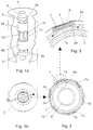
- Fig. 1a and 1b show an embodiment of the invention Resonators.
- the necessary thermal insulation outside around the resonator and inside between a measurement sample 5 and a carrier glass 3 are not explicitly shown.
- the values for the dimensions of the resonator listed below refer to a resonator that is built for a cylindrical measurement sample with a diameter of 5 mm. Other values would result accordingly for other measurement samples.
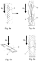
- the superconducting components 1, 1a, 1b to 1f represent the main parts of the resonator lying parallel to the H 0 field. These are composed of the long, narrow crystal platelets 9 shown in cross section in FIG. 3 (for example approx. 4 mm wide, approx. 45 mm long and approx. 0.5 mm thick), on the outside of which the superconducting coating 8 (approx. 0.5 ⁇ m thick) is applied.
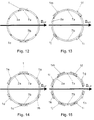
- a six-element arrangement is shown in FIG. 2, but more or fewer platelets can also be used which are arranged on a cylindrical surface lying coaxially to the measurement sample (see FIGS. 12, 13 and 15).
- the superconducting components 1, 1a to 1e lie on the two connecting rings 2a and 2b (e.g. 10 mm diameter and 15 mm wide), which is made of a metallic, electrically good conductive material (e.g. 20 ⁇ m thick foils made of copper, aluminum or silver), and around the carrier glass 3 can be placed.
- the superconducting components are with the two pressing devices 4a and 4b on the two pressed annular connecting elements 2a and 2b, whereby the two connecting rings also have a mechanical hold.
- the pressing devices 4a, 4b are, for example Teflon tapes that fill the superconducting components 1 to 1e are wrapped. Adjacent areas between the superconducting layers and the two connecting rings represent capacitive parts of the resonator. Their capacitance values are determined by the dielectric constant of the crystal platelets advantageously increased.
- the two connecting rings on two to each other Diametrically positioned positions interrupted parallel to the axis are the two connecting rings on two to each other Diametrically positioned positions interrupted parallel to the axis (Interrupt channels 7a and 7b).
- the two interrupt channels 7a and 7b are included an odd value of m below the center of a superconducting Component (see Fig. 14) at an even value of m in the middle between two superconducting components (see Fig. 15).
- the interrupt channels 7a and 7b have another advantage. They reduce the eddy currents in the connecting rings 2a and 2b, which when switching the z gradients can arise.
- An RF shield is around the arrangement described 6 attached, which is usually cylindrical and electric must be well conductive so that the HF losses are not too great be transformed into the resonator. You can out a normally conductive material, e.g. a silver-plated copper pipe, or even better consist of a superconductor.
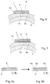
- connection of the superconducting components 1, 1a to 1e with the connecting rings 2a and 2b can also with the help of a Low susceptibility lots occur, as shown in FIG. 6 is shown.
- a metal e.g. Copper coated (metal layer 12)
- metal layer 12 metal layer 12
- FIG. 7 Another possibility for fastening the superconducting components is shown in FIG. 7.
- the superconducting components are mounted upside down, ie with the superconducting layer 8 inwards, and thin, electrically insulating plates 13 are placed between the superconducting components and the connecting rings, which serve as a dielectric for the capacitive components of the resonator.
- Such a pane may only have very low dielectric losses in the HF range and may consist of a plastic (e.g. a Teflon compound), or even better of a thin ceramic pane (e.g. Al 2 O 3 ) with a suitably high dielectric constant (e.g. 9.8).
- the pressing devices 4a and 4b are in turn used to fasten these parts.
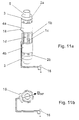
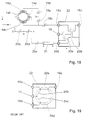
- FIGS. 9a, 9b, 10, 11a and 11b show different possibilities, to couple the NMR signal out of the resonator.
- the capacitive decoupling is shown in FIGS. 9a and 9b.
- the direction of the RF field B HF of the resonator is fixed with the two interrupt channels 7a and 7b, namely perpendicular to the plane which runs through the two interrupt channels.
- Two metallic foils 14a and 14b (for example made of copper, aluminum or silver) are attached in an electrically insulating manner over the pressing device 4b and the two interruption channels. They represent two coupling capacitances that act between the foils and the superconducting components. Since the resonator is an electrically symmetrical arrangement, a capacitive coupling network 15a, 15b and 15c is also constructed symmetrically.
- the NMR signal is forwarded via a low-resistance coaxial line 16 of, for example, 50 ohms. So that the symmetry condition of the coupling network is fulfilled, the capacitance 15b must be approximately equal to the sum of the two capacitances 15a and 15c.
- the degree of coupling to the coaxial line 16 can be set using the ratio of the two capacitances 15a and 15c.
- the 10 represents a galvanic decoupling.
- the contacts are located directly on the two superconducting components 1b and 1c, which are symmetrical to the direction of the B HF field.
- An decoupling network 17a, 17b and 17c can be selected here in the same way as for capacitive decoupling.
- 11a and 11b show an inductive coupling.
- An inductive loop 18 is attached to the side of the resonator, in such a way that the surface of the loop is perpendicular to the direction of the B HF field.
- the coupling to the resonator can be changed by moving and rotating the loop.
- the resonance frequency of the resonator must be set using additional means, which are not shown here. This can be, for example, a cylindrical, metallic ring which lies in the area of the connecting rings 2a and 2b above the pressing device 4a and can be axially displaced. This creates a variable capacitive load on the resonator, with which the resonance frequency can be set.
- the "Bird-Cage" resonator can also as a quadrature detector for the reception of rotating fields be used.
- This possibility arises thanks to his symmetrical structure, with the two perpendicular to each other standing, identical decouplings 14c and 14d and 14e and 14f are possible (see Fig. 18), which are electrical and magnetic are decoupled from each other.
- the NMR rotating field turns into the xy plane and generates at the two capacitive decouplings two NMR signals shifted in time by 90 ° to each other are.
- NMR signals are obtained using the Capacities 19a, 19b and 19c as well as 20a, 20b, and 20c to 50 Ohm transformed down in terms of impedance and then to the RF sockets 16a and 16b of a power splitter / combiner 22 performed where the two NMR signals added and on the output socket 16 are routed.
- the output socket is in turn with the preamplifier (not shown) connected.
- the two NMR signals are at 90 ° to one another out of phase. To get the full one at the addition To use the power of the two NMR signals, they must be in Phase are added, i.e. one of these signals still has to experience an additional phase shift of 90 ° what is achieved using the ⁇ / 4 line 21.
- the two NMR signals at the RF sockets 16a and 16b either depending on the direction of rotation of the NMR rotating field can be in phase or in opposite phase. In the case of the opposite phase the two signals would totally compensate for what must of course be prevented. If this happens then the capacitance 20c with point B and no more be connected to point A.
- the power splitter / combiner 22 is composed of the two ideal transformers 23a and 23b and essentially represents a symmetrical bridge circuit, which firstly completely decouples the transmission signal at the input socket 16c from the NMR signal at the output socket 16, and secondly the powers of the two NMR signals at the sockets 16a and 16b added losslessly and leads to the output 16, and thirdly the available transmission power at the socket 16c losslessly and evenly to the two sockets 16a and 16b, which via the capacitive network with the resonator connected, distributed.
- the ideal transformers have to be replaced by practically realizable circuits. In the HF area, circuits that are constructed with HF lines are best suited, for example ring-shaped HF lines, so-called ring lines.
- the ring line consists of three ⁇ / 4 lines 24a, 24b, 24c and a 3 ⁇ / 4 line 24d, all four lines having a common characteristic impedance, which is by the factor 2nd is greater (eg 71 ohms) than the characteristic impedance of the ⁇ / 4 line 21 and the two lines which are connected to the sockets 16 and 16c (eg 50 ohms).
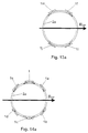
- Fig. 20a shows a possible arrangement. Seen electrically the two parts 8 'and 8' 'represent two inductors, the are connected to each other via a capacity. The ends of the two parts 8 'and 8' 'are galvanically connected to the connecting rings 2a and 2b connected. Instead of galvanic A capacitive connection is also possible, whereby preferably the capacity of this connection is greater than should be much larger than the finger-shaped capacity.
- Fig. 20b shows a possible arrangement as in this Case the two superconducting coatings 8 'and 8' 'in fine strips 8a, 8b, 8c, ... can be divided to to keep the magnetization of the superconductor low.
Claims (12)
- Résonateur haute fréquence (HF) pour l'émission et/ou la réception résonante de signaux HF à une fréquence de résonance souhaitée dans ou à partir d'un échantillon de mesure (5) dans un volume d'analyse dans le champ magnétique homogène B0 d'un appareil à résonance magnétique nucléaire (RMN), le résonateur HF comprenant des composants supraconducteurs, caractérisé en ce que le résonateur HF présente au moins deux composants (1, 1a, 1b ... 1m) supraconducteurs à l'état de service, spatialement séparés les uns des autres, qui ne constituent ni pris individuellement, ni ensemble un système résonant fermé pouvant osciller en résonance à la fréquence de résonance souhaitée, en ce qu'il est prévu des éléments de liaison (2a, 2b) normalement conducteurs à l'état de service, qui relient entre eux les composants supraconducteurs (1, 1a, ... 1m) de façon galvanique ou capacitive de telle sorte que les composants supraconducteurs (1, 1a, ... 1m) forment, conjointement avec les éléments de liaison normalement conducteurs (2a, 2b) et des moyens supplémentaires pour régler la fréquence de résonance, un ou plusieurs systèmes résonants fermés capables d'osciller en résonance à la fréquence de résonance souhaitée, et en ce que les composants supraconducteurs (1, 1a, ... 1m) et les éléments de liaison (2a, 2b), qui leur sont reliés de façon galvanique ou capacitive, forment un résonateur dit « en cage » (en anglais « birdcage resonator ») à symétrie ponctuelle ou axiale, les composants supraconducteurs (1, 1a, ... 1m) formant les parties conductrices axiales et les éléments de liaison normalement conducteurs (2a, 2b) les parties conductrices annulaires de la structure « en cage ».
- Résonateur HF selon la revendication 1, caractérisé en ce que les composants supraconducteurs (1, 1a, ... 1m) consistent en des lamelles (9) étroites et oblongues, pourvues d'un revêtement supraconducteur (8), qui sont respectivement disposées en étant orientées parallèlement au champ magnétique B0 et en étant réparties sur une surface cylindrique dont l'axe est parallèle au champ magnétique B0 et coïncide avec l'axe de l'échantillon de mesure (5).
- Résonateur HF selon la revendication 2, caractérisé en ce que le revêtement supraconducteur (8) est réparti en un nombre maximal de fines bandelettes (8a, 8b, 8c, ...) qui sont toutes orientées parallèlement au champ magnétique B0.
- Résonateur HF selon la revendication 2 ou 3, caractérisé en ce que le revêtement supraconducteur (8) est subdivisé en au moins deux zones (8' et 8"), qui sont reliées entre elles de façon capacitive.
- Résonateur HF selon une des revendications 2 à 4, caractérisé en ce que le revêtement supraconducteur (8) est constitué d'un supraconducteur à haute température, YBCO par exemple.
- Résonateur HF selon une des revendications 2 à 5, caractérisé en ce que les lamelles (9) sont constituées d'un cristal à structure cristalline appropriée, LaAlO3 par exemple, ou de saphir.
- Résonateur HF selon une des revendications 2 à 6, caractérisé en ce que les composants supraconducteurs (1, 1a, ... 1m) sont reliés à leurs deux extrémités axiales, de façon capacitive ou galvanique, à des éléments de liaison (2a, 2b) normalement conducteurs métalliques et annulaires, présentant une haute conductivité.
- Résonateur HF selon la revendication 7, caractérisé en ce que les éléments de liaison (2a, 2b) présentent en deux points diamétralement opposés des canaux d'interruption (7a, 7b) qui s'étendent parallèlement à l'axe de la surface cylindrique, de sorte qu'on obtient une répartition prédéfinie du courant dans le résonateur.
- Résonateur HF selon la revendication 8, caractérisé en ce que, pour un agencement avec 2 x m composants supraconducteurs (1, 1 a, ... 1m), les canaux d'interruption (7a, 7b) se trouvent, au milieu en dessous d'un composant supraconducteur si m est impair, et au milieu entre deux composants supraconducteurs voisins si m est pair.
- Résonateur HF selon une des revendications précédentes, caractérisé en ce que le découplage d'un signal RMN provenant du résonateur « en cage » s'effectue au moyen d'un couplage capacitif (14a).
- Résonateur HF selon une des revendications 1 à 9, caractérisé en ce que le découplage d'un signal RMN provenant du résonateur « en cage » s'effectue au moyen d'un couplage galvanique, de préférence au moyen de mises en contact directes des revêtements supraconducteurs (8).
- Résonateur HF selon la revendication 10 ou 11, caractérisé en ce que le résonateur « en cage » présente deux découplages orthogonaux (14c, 14d et 14e, 14f), qui permettent une détection de quadrature.
Applications Claiming Priority (2)
| Application Number | Priority Date | Filing Date | Title |
|---|---|---|---|
| DE19733574A DE19733574C2 (de) | 1997-08-02 | 1997-08-02 | Supraleitender Hybrid-Resonator für den Empfang für NMR-Signalen |
| DE19733574 | 1997-08-02 |
Publications (2)
| Publication Number | Publication Date |
|---|---|
| EP0895092A1 EP0895092A1 (fr) | 1999-02-03 |
| EP0895092B1 true EP0895092B1 (fr) | 2000-10-11 |
Family
ID=7837879
Family Applications (1)
| Application Number | Title | Priority Date | Filing Date |
|---|---|---|---|
| EP98113745A Expired - Lifetime EP0895092B1 (fr) | 1997-08-02 | 1998-07-23 | Résonateur hybride supraconducteur pour la réception de signaux RMN |
Country Status (4)
| Country | Link |
|---|---|
| US (1) | US6121776A (fr) |
| EP (1) | EP0895092B1 (fr) |
| JP (1) | JP3066359B2 (fr) |
| DE (2) | DE19733574C2 (fr) |
Cited By (1)
| Publication number | Priority date | Publication date | Assignee | Title |
|---|---|---|---|---|
| US11959984B2 (en) | 2020-12-15 | 2024-04-16 | Quantum Valley Investment Fund LP | Model-insensitive control of nonlinear resonators |
Families Citing this family (26)
| Publication number | Priority date | Publication date | Assignee | Title |
|---|---|---|---|---|
| US6377047B1 (en) * | 2000-06-08 | 2002-04-23 | Varian, Inc. | Superconducting birdcage coils |
| DE10118835C2 (de) | 2001-04-17 | 2003-03-13 | Bruker Biospin Ag Faellanden | Supraleitende Resonatoren für Anwendungen in der NMR |
| DE10150131C2 (de) | 2001-10-11 | 2003-10-09 | Bruker Biospin Ag Faellanden | HF-Empfangsspulenanordnung für einen NMR-Resonator mit makroskopisch homogener Verteilung der Leiterstrukturen |
| JP2003130937A (ja) * | 2001-10-24 | 2003-05-08 | Hitachi Ltd | 溶液用核磁気共鳴分析装置 |
| DE10157972B4 (de) * | 2001-11-27 | 2004-01-08 | Bruker Biospin Ag | NMR-Spektrometer und Betriebsverfahren mit Stabilisierung der transversalen Magnetisierung bei supraleitenden NMR-Resonatoren |
| DE10203279C1 (de) * | 2002-01-29 | 2003-10-09 | Bruker Biospin Ag | Verfahren zur Beeinflussung des homogenen statischen Magnetfelds in einer NMR-Apparatur und zugehöriger NMR-Resonator |
| JP2003255032A (ja) * | 2002-02-28 | 2003-09-10 | Hitachi Ltd | 核磁気共鳴装置用プローブ |
| JP3993127B2 (ja) * | 2003-04-24 | 2007-10-17 | 株式会社日立製作所 | Nmr装置用超電導プローブコイル |
| JP4090389B2 (ja) | 2003-06-10 | 2008-05-28 | 株式会社日立製作所 | 核磁気共鳴装置 |
| US7859264B2 (en) | 2004-01-20 | 2010-12-28 | The University Of Houston | Superconducting loop, saddle and birdcage MRI coils capable of simultaneously imaging small nonhuman animals |
| US7295009B2 (en) * | 2004-03-10 | 2007-11-13 | Bruker Biospin Corporation | Planar NMR coil with gyromagnetic arc suppression |
| DE102004020167B4 (de) * | 2004-04-24 | 2012-01-05 | Bruker Biospin Ag | Hochfrequenz-Resonatorsystem mit optimierter Stromverteilung in den Leiterelementen und Verfahren zu dessen Design |
| DE102004035851B4 (de) | 2004-07-23 | 2006-11-16 | Bruker Biospin Ag | Resonatorsystem zur Erzeugung eines Hochfrequenz-Magnetfelds |
| JP4279747B2 (ja) | 2004-08-11 | 2009-06-17 | 株式会社日立製作所 | 核磁気共鳴装置 |
| JP4647984B2 (ja) | 2004-12-02 | 2011-03-09 | 株式会社日立製作所 | 核磁気共鳴プローブコイル |
| WO2006122203A1 (fr) * | 2005-05-11 | 2006-11-16 | The University Of Houston System | Systeme de magnetocapteur intraluminal et procede d'utilisation |
| US8380279B2 (en) * | 2005-05-11 | 2013-02-19 | The University Of Houston System | Intraluminal multifunctional sensor system and method of use |
| US20090295385A1 (en) * | 2005-05-11 | 2009-12-03 | Audrius Brazdeikis | Magneto Sensor System and Method of Use |
| JP4673188B2 (ja) * | 2005-10-28 | 2011-04-20 | 株式会社日立製作所 | 核磁気共鳴装置用のnmrプローブ |
| DE102006011254B4 (de) * | 2006-03-10 | 2009-01-29 | Siemens Ag | Magnetresonanzanlage mit supraleitender Ganzkörper-Empfangsanordnung |
| JP4971685B2 (ja) * | 2006-05-25 | 2012-07-11 | 株式会社日立製作所 | 核磁気共鳴プローブコイル |
| US8564294B2 (en) | 2011-06-28 | 2013-10-22 | Agilent Technologies, Inc. | Nuclear magnetic resonance probe comprising slit superconducting coil with normal-metal overlayer |
| JP6048868B2 (ja) * | 2012-06-29 | 2016-12-21 | 国立研究開発法人理化学研究所 | 核磁気共鳴現象測定用rfコイル |
| JP6245899B2 (ja) * | 2012-08-29 | 2017-12-13 | 東芝メディカルシステムズ株式会社 | 高周波コイル及び磁気共鳴イメージング装置 |
| DK3198348T3 (da) | 2014-09-24 | 2020-05-11 | Quantum Valley Invest Fund Lp | Generering af en styresekvens til kvantestyring |
| CA3104011C (fr) * | 2018-07-25 | 2024-01-02 | Quantum Valley Investment Fund LP | Commande de resonateurs non lineaires non sensible a un modele |
Family Cites Families (4)
| Publication number | Priority date | Publication date | Assignee | Title |
|---|---|---|---|---|
| US5258710A (en) * | 1992-03-27 | 1993-11-02 | General Electric Company | Cryogenic probe for NMR microscopy |
| US5585723A (en) * | 1995-03-23 | 1996-12-17 | Conductus, Inc. | Inductively coupled superconducting coil assembly |
| DE4218635C2 (de) * | 1992-06-05 | 1996-05-23 | Siemens Ag | Hochfrequenz-Empfangsantenne einer Einrichtung zur Kernspintomographie mit mindestens einem Kondensator |
| EP0738897B1 (fr) * | 1995-03-25 | 2000-08-09 | Bruker AG | Dispositif de bobines de réception HF pour spectromètre RMN |
-
1997
- 1997-08-02 DE DE19733574A patent/DE19733574C2/de not_active Expired - Lifetime
-
1998
- 1998-07-20 US US09/118,943 patent/US6121776A/en not_active Expired - Lifetime
- 1998-07-23 EP EP98113745A patent/EP0895092B1/fr not_active Expired - Lifetime
- 1998-07-23 DE DE59800296T patent/DE59800296D1/de not_active Expired - Fee Related
- 1998-08-03 JP JP10229959A patent/JP3066359B2/ja not_active Expired - Fee Related
Cited By (1)
| Publication number | Priority date | Publication date | Assignee | Title |
|---|---|---|---|---|
| US11959984B2 (en) | 2020-12-15 | 2024-04-16 | Quantum Valley Investment Fund LP | Model-insensitive control of nonlinear resonators |
Also Published As
| Publication number | Publication date |
|---|---|
| JP3066359B2 (ja) | 2000-07-17 |
| EP0895092A1 (fr) | 1999-02-03 |
| DE59800296D1 (de) | 2000-11-16 |
| DE19733574C2 (de) | 2000-04-06 |
| DE19733574A1 (de) | 1999-02-04 |
| US6121776A (en) | 2000-09-19 |
| JPH11133127A (ja) | 1999-05-21 |
Similar Documents
| Publication | Publication Date | Title |
|---|---|---|
| EP0895092B1 (fr) | Résonateur hybride supraconducteur pour la réception de signaux RMN | |
| EP1251361B1 (fr) | Résonateurs supraconducteurs pour des applications dans la RMN | |
| DE69636756T2 (de) | Sondenspule für die Kernspinresonanz | |
| DE102004035851B4 (de) | Resonatorsystem zur Erzeugung eines Hochfrequenz-Magnetfelds | |
| DE102005047883B4 (de) | Kernspinresonanz-Messkopf umfassend mindestens zwei Spulen/Resonatoranordnungen mit reduzierter Kopplung | |
| EP0223284B1 (fr) | Arrangement de bobines haute-fréquence pour appareil pour la résonance de spin nucléaire | |
| KR100349277B1 (ko) | 평면 필터 및 필터 시스템 | |
| DE102013204952B3 (de) | Aktiv abgeschirmtes zylinderförmiges Gradientenspulensystem mit passiver HF-Abschirmung für NMR-Apparate | |
| EP0293723A2 (fr) | Système de bobines magnétiques d'une installation pour l'imagerie RMN, muni de bobines supraconductrices et d'un écran protégeant des rayonnements parasites | |
| EP0738897A1 (fr) | Dispositif de bobines de réception HF pour spectromètre RMN | |
| DE202004021683U1 (de) | NMR-Sonde mit einer inneren Quadratur-Erfassungsspule in Kombination mit einer spiralförmig gewundenen, äußeren Spule zur Bestrahlung | |
| DE19844895C2 (de) | Probenkopf für ein NMR-Spektrometer | |
| DE1673268C3 (de) | Sonde für Resonanzspektrometer | |
| DE4218635C2 (de) | Hochfrequenz-Empfangsantenne einer Einrichtung zur Kernspintomographie mit mindestens einem Kondensator | |
| DE10121449A1 (de) | MR-Gerät mit einem offenen Magnetsystem und einer Quadratur-Spulenanordnung | |
| DE10354676A1 (de) | Niederresistive Abschirmung | |
| EP0890113B1 (fr) | Dispositif de couplage d'un magnetometre hf a anneau de commutation a un circuit bouchon supraconducteur | |
| DE102015206788B3 (de) | NMR Sende/Empfangsspulenanordnung | |
| EP1302780A1 (fr) | Résonateurs RMN supraconducteurs avec une distribution macroscopiquement homogène du supraconducteur | |
| EP3315988A1 (fr) | Ensemble résonateur rf | |
| EP0429791B1 (fr) | Dispositif pour syntoniser un résonateur | |
| DE102012222253A1 (de) | Magnetische kernresonanzsonde mit infrarot-reflexionsflächen | |
| EP0193783A1 (fr) | Système d'antenne haute fréquence pour dispositif de tomographie de spin nucléaire | |
| DE102012210815A1 (de) | Magnetische kernresonanzsonde mit schlitz-superleit-spule mit normalmetallüberschicht |
Legal Events
| Date | Code | Title | Description |
|---|---|---|---|
| PUAI | Public reference made under article 153(3) epc to a published international application that has entered the european phase |
Free format text: ORIGINAL CODE: 0009012 |
|
| AK | Designated contracting states |
Kind code of ref document: A1 Designated state(s): CH DE FR GB LI |
|
| AX | Request for extension of the european patent |
Free format text: AL;LT;LV;MK;RO;SI |
|
| 17P | Request for examination filed |
Effective date: 19990108 |
|
| 17Q | First examination report despatched |
Effective date: 19990526 |
|
| AKX | Designation fees paid |
Free format text: CH DE FR GB LI |
|
| GRAG | Despatch of communication of intention to grant |
Free format text: ORIGINAL CODE: EPIDOS AGRA |
|
| GRAG | Despatch of communication of intention to grant |
Free format text: ORIGINAL CODE: EPIDOS AGRA |
|
| GRAH | Despatch of communication of intention to grant a patent |
Free format text: ORIGINAL CODE: EPIDOS IGRA |
|
| GRAH | Despatch of communication of intention to grant a patent |
Free format text: ORIGINAL CODE: EPIDOS IGRA |
|
| GRAA | (expected) grant |
Free format text: ORIGINAL CODE: 0009210 |
|
| AK | Designated contracting states |
Kind code of ref document: B1 Designated state(s): CH DE FR GB LI |
|
| REG | Reference to a national code |
Ref country code: CH Ref legal event code: NV Representative=s name: RIEDERER HASLER & PARTNER PATENTANWAELTE AG Ref country code: CH Ref legal event code: EP |
|
| REF | Corresponds to: |
Ref document number: 59800296 Country of ref document: DE Date of ref document: 20001116 |
|
| GBT | Gb: translation of ep patent filed (gb section 77(6)(a)/1977) |
Effective date: 20010105 |
|
| ET | Fr: translation filed | ||
| PLBE | No opposition filed within time limit |
Free format text: ORIGINAL CODE: 0009261 |
|
| STAA | Information on the status of an ep patent application or granted ep patent |
Free format text: STATUS: NO OPPOSITION FILED WITHIN TIME LIMIT |
|
| 26N | No opposition filed | ||
| REG | Reference to a national code |
Ref country code: GB Ref legal event code: IF02 |
|
| REG | Reference to a national code |
Ref country code: CH Ref legal event code: PFA Free format text: BRUKER AG TRANSFER- BRUKER BIOSPIN AG |
|
| PGFP | Annual fee paid to national office [announced via postgrant information from national office to epo] |
Ref country code: DE Payment date: 20020727 Year of fee payment: 5 |
|
| REG | Reference to a national code |
Ref country code: FR Ref legal event code: CD |
|
| PG25 | Lapsed in a contracting state [announced via postgrant information from national office to epo] |
Ref country code: DE Free format text: LAPSE BECAUSE OF NON-PAYMENT OF DUE FEES Effective date: 20040203 |
|
| REG | Reference to a national code |
Ref country code: CH Ref legal event code: PCAR Free format text: RIEDERER HASLER & PARTNER PATENTANWAELTE AG;ELESTASTRASSE 8;7310 BAD RAGAZ (CH) |
|
| PGFP | Annual fee paid to national office [announced via postgrant information from national office to epo] |
Ref country code: CH Payment date: 20140722 Year of fee payment: 17 |
|
| PGFP | Annual fee paid to national office [announced via postgrant information from national office to epo] |
Ref country code: GB Payment date: 20140721 Year of fee payment: 17 Ref country code: FR Payment date: 20140724 Year of fee payment: 17 |
|
| REG | Reference to a national code |
Ref country code: CH Ref legal event code: PL |
|
| GBPC | Gb: european patent ceased through non-payment of renewal fee |
Effective date: 20150723 |
|
| PG25 | Lapsed in a contracting state [announced via postgrant information from national office to epo] |
Ref country code: LI Free format text: LAPSE BECAUSE OF NON-PAYMENT OF DUE FEES Effective date: 20150731 Ref country code: GB Free format text: LAPSE BECAUSE OF NON-PAYMENT OF DUE FEES Effective date: 20150723 Ref country code: CH Free format text: LAPSE BECAUSE OF NON-PAYMENT OF DUE FEES Effective date: 20150731 |
|
| REG | Reference to a national code |
Ref country code: FR Ref legal event code: ST Effective date: 20160331 |
|
| PG25 | Lapsed in a contracting state [announced via postgrant information from national office to epo] |
Ref country code: FR Free format text: LAPSE BECAUSE OF NON-PAYMENT OF DUE FEES Effective date: 20150731 |